
Abstract
The tissue engineering community has been vocal regarding the need for noninvasive instruments to assess the development of tissue-engineered constructs. Medical imaging has helped fulfill this role. However, specimens allocated to a test tube for imaging cannot be tested for a prolonged period or returned to the incubator. Therefore, samples are essentially wasted due to potential contamination and transfer in a less than optimal growth environment. In turn, we present a standalone, miniature, magnetic resonance imaging-compatible incubator, termed the e-incubator. This incubator uses a microcontroller unit to automatically sense and regulate physiological conditions for tissue culture, thus allowing for concurrent tissue culture and evaluation. The e-incubator also offers an innovative scheme to study underlying mechanisms related to the structural and functional evolution of tissues. Importantly, it offers a key step toward enabling real-time testing of engineered tissues before human transplantation. For validation purposes, we cultured tissue-engineered bone constructs for 4 weeks to test the e-incubator. Importantly, this technology allows for visualizing the evolution of temporal and spatial morphogenesis. In turn, the e-incubator can filter deficient constructs, thereby increasing the success rate of implantation of tissue-engineered constructs, especially as construct design grows in levels of complexity to match the geometry and function of patients' unique needs.
Introduction
T
The concept of tissue engineering was introduced over 25 years ago, but a limited number of products have been approved for clinical application. 4 The tissue engineering community has been vocal in seeking noninvasive instruments to assess and steer the development of tissue-engineered constructs. 5 Thus, offering an instrument that can facilitate noninvasive visualization capabilities using traditional medical imaging technologies is expected to expedite the translation of tissue-engineered products to clinical settings.
Medical imaging technologies have proved their superiority in clinical settings for the diagnosis of various diseases. These imaging technologies have the potential to play a major role in tissue culture applications. Among such imaging technologies, MRI is highly desirable because it does not use ionizing radiation and is, therefore, well suited for longitudinal studies. However, one major problem is that a specimen allocated to a test tube for imaging cannot be tested for a prolonged period of time nor can it be returned to the incubator. In turn, the sample is wasted due to potential contamination and transfer in a suboptimal growth environment. Until this problem is resolved, the benefits that medical imaging can provide to these diverse fields cannot be fully realized. In this article, we present a miniature MRI-compatible incubator, termed the e-incubator. The e-incubator is an initial step in developing the next generation of instruments that can enable real-time, on-board imaging for tissue specimen testing and clinical applications. The e-incubator is a standalone unit that is controlled through a microcontroller unit (MCU). The MCU acts as a central control unit to automatically sense and regulate physiological conditions (e.g., temperature, CO2, and pH) and to perform media exchange for cultured constructs. In the current design of the e-incubator, MRI compatibility is pursued because MRI represents the most sophisticated clinically viable technique available today. With proper adjustments, the design of the e-incubator can be revised to incorporate other imaging modalities such as computed tomography and optical imaging.
Since late 1990s, perfusion-based tissue culture systems, such as hollow fiber bioreactors (HFBRs), have been designed in parallel with improvements in high-resolution MRI. While HFBRs are compatible with MRI, most of the available designs fail to address how to maintain an optimal growth environment for tissues. Additionally, most HFBRs can only function in a continuous perfusion mode, which requires a pause in flow during imaging sessions. In turn, the quality of the MR images is compromised by magnetic susceptibility artifacts due to hollow fibers.6–8 Still, these studies highlight the continuous pursuit of technological innovation to dynamically monitor the development of tissue-engineered constructs. Importantly, the invention of the e-incubator provides a standalone unit that eliminates the need to use unwieldy incubator units. Our concurrent tissue culture and evaluation approach offers an innovative scheme to study, in real time, the underlying mechanisms associated with the structural and functional evolution of tissues while they are growing.
Given its clinical significance, we selected tissue-engineered bone as a model system to demonstrate the feasibility of our instrument. Trauma, osteoporosis, and bone cancer together cause over two million cases of bone injury or loss in the United States annually. 9 Natural bone healing following injury or disease is the preferred option to overcome osteogenic tissue loss and bone damage. However, because bone has a limited capability to regenerate and remodel, often the surgeon will need to implant synthetic materials or bone grafts at the site of injury. Specifically, for fractures that do not heal naturally, ∼1 million cases of bone grafts are performed annually in the United States as treatment, resulting in an estimated annual cost of over $3 billion. Both autologous and allogeneic bone grafts are used clinically as bone substitutes. However, the availability of compatible grafts is limited given that harvesting bone is painful and the procedure carries significant risk of infection. Therefore, tissue-engineered bone has emerged as a promising alternative for creating functional substitutes. 10 Still, one challenge in the clinical utility of tissue-engineered bone is the avoidance of nonspecific tissue development (i.e., ensuring stable expression of the osteogenic phenotype before implantation). In particular, the clinically relevant event that murine mesenchymal stem cells (MSCs) can transform into a malignant disease during in vivo regeneration has been documented.11,12
Successful tissue engineering requires gradual assessment of developing tissues. The different growth stages of tissue-engineered bone constructs are defined by changes in the osteogenic phenotype (i.e., cell proliferation followed by extracellular matrix [ECM] development and finally bone mineralization). Specific gene expression at each stage characterizes this progression. 13 Conventional biochemical and immunohistochemical analyses provide critical markers of osteogenic development, including alkaline phosphatase (ALP), collagen type 1 (COLL1), osteopontin (OPN), osteocalcin (OCN), and bone sialoprotein (BSP).14–16 For example, OCN is a bone turnover marker and appears concurrently with ECM mineralization.17,18 Nevertheless, such immunohistochemical analyses are destructive to the tissue.
Currently, no reliable technique has been established that can measure osteogenic phenotype expression for tissue-engineered constructs in a continuous and noninvasive manner, similar to the proposed technique in this study. Only recently have researchers begun to explore the potential for medical imaging techniques to monitor developing bone tissues. In particular, MRI can visualize structural and functional changes associated with bone formation.2,7,8,19,20 For example, MRI relaxometry parameters, such as T2-relaxation time, can be correlated with ALP activity. Similarly, evaluation of the MT effect can reveal changes, with high specificity, in collagen content associated with osteogenesis.
Materials and Methods
Specimen preparation
Osteogenic tissue-engineered constructs were prepared using human MSCs (hMSCs) isolated from donated, commercially available, fresh adult human bone marrow (Lonza, Walkersville, MD) seeded into a biodegradable, sterile, gelatin scaffold (Gelfoam®; Baxter Healthcare Corporation, Hayward, CA); this scaffold was trimmed into 3.5×3.5×4 mm sections at a density of 106 cells/mL. Second, similar constructs were prepared using aqueous silk sponges 21 with dimensions of 8×3 mm at a density of 10×106 cells/mL. For both constructs, sterile scaffolds were placed in 24-well plate seeded with hMSCs and placed in the incubator. Following 2 h, additional growth medium was added to the wells. After 24 h, the medium was replaced with the osteogenic medium containing Dulbecco's modified Eagle's medium, 10% fetal bovine serum, 0.5% antibiotic/antimycotic, 100 nM dexamethasone, 10 mM, β-glycerophosphate, and 0.05 mM ascorbic acid 2-phosphate (Sigma, St. Louis, MO). Forty-eight hours postseeding, one osteogenic construct was placed in the e-incubator, whereas the other was maintained in a standard incubator. For studying both constructs simultaneously inside the e-incubator, the silk scaffold was punched into a 5 mm diameter.
e-Incubator design
The MRI-compatible e-incubator (patent pending; application number: 13/953,984) provides an enclosed but autonomously controlled and user-configurable environment for tissue culture and development in vitro (Fig. 1). Pictures of the system components are presented in Supplementary Figures S1 and S2 (Supplementary Data are available online at
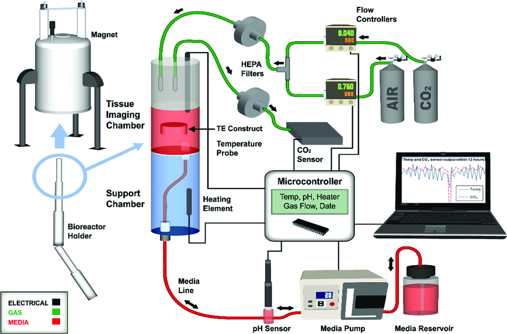
Schematic of the plug-and-play e-incubator (i.e., loading the e-incubator unit inside the magnet is achieved in less than 15 min) where the microcontroller unit (MCU) is the brain controlling e-incubator culture environment. The MCU initiates the peristaltic pump to flow a predetermined level of fresh medium to the tissue imaging (TI) chamber while the culture environment is maintained for temperature, CO2, and pH. The system functions as follows: (1) a feedback system maintains the CO2 level by activating two flow meters for mixing CO2 and air based on the value recorded by the CO2 sensor positioned on the output flow from the TI chamber; (2) the temperature, measured by (3), adjusts the quality of the medium through scheduled exchange three times a day, during which time a sensor measures the pH value. The MCU continuously acquires data from the sensors for the gas and temperature, while the pH is evaluated only during medium changes; the pH is sent through a serial port for documentation. Multiple safety features are built within the system, including a magnetic resonance (MR)-compatible thermistor to protect the circuit from overheating, and ports in the chamber and medium reservoir to ensure that pressure does not build within the system. Color images available online at
The e-incubator system incorporated signal processing of all sensors, pump and heater driving, communication with user interface, and the data logging application using a PIC16f1917 MCU (Microchip Technology, Inc.). This is an 8-bit model that includes eight channels, inbuilt 10-bit resolution analog-to-digital converter. The MCU software communicated between all sensors and other electrical and mechanical elements through a preprogrammed C program to ensure environmental conditions (i.e., temperature, CO2, and pH) were properly maintained for optimal growth of the tissue-engineered construct. When turning on the system for the first time, an initialization is used to pump the media out from the culture chamber and replace it with fresh media. The system includes an overheating protection circuit to shut down the heaters in case of temperature probe failure. All data, including temperature, pH value, CO2 control system status, date, and time, were shown on a liquid crystal display and transferred to a personal computer (PC) using a serial port. Finally, a surveillance camera was used for observation over the internet using a smartphone.
e-Incubator setup and loading
The e-incubator was composed of an upper TI chamber and lower heating chamber, machined from stock polycarbonate. Initially, adapted Transwell-Clear Permeable (Corning, Inc., Corning, NY) plate inserts were modified and positioned within the TI chamber for containment of the tissue construct. A nylon washer and meshing was situated on top of the insert to keep the construct from floating out of the insert. To avoid bubbles that interfere with imaging, a new tissue holder was designed and manufactured from polysulfone.
Before setup of the e-incubator, all tubes and connections were placed in sterilization pouches for a steam autoclave, including the tissue holder. In a biosafety cabinet, the TI chamber and pH probe were sterilized with 1 M NaOH for 1 h, followed by three rinses with sterile dH2O, and loaded basic medium until setup. A sterile 250 mL Fisherbrand bottle was filled with 100 mL of osteogenic medium (as above) and connected with the three-hole lid. The three-hole lid was connected to the medium tubing that connected to the pH meter flow-through cell. The opposite end of the flow-through cell connected to additional tubing that was threaded through the e-incubator holder and connected to the bottom of the heating chamber. The tubing for the gas lines were also threaded through the holder and affixed to the TI chamber lid after the construct was loaded. An osteogenic construct was placed in the tissue holder inside the TI chamber and a 3D printed lid was placed on top to keep it within the holder. All parts were removed from the biosafety cabinet, the medium tube placed in the peristaltic pump, gas tubes connected, and the pH meter, heater, and temperature probe wires connected to the MCU. The MCU was turned on and the program initiated. The chamber was attached to the e-incubator holder with nylon set screws and placed within the magnet. Initial imaging was performed to evaluate placement of the chamber and tissue in the magnet.
Device verification
The e-incubator samples were tested daily for 4 weeks with MRI by measuring different MR parameters. Following the e-incubator culture, the samples were removed from the traditional incubator and the e-incubator, cut into two halves and tested by live–dead assay and conventional histology. Different constructs cultured in the e-incubator were compared by measuring different MR parameters followed by histology as detailed below.
Magnetic resonance imaging
The tissue-engineered bone construct was loaded into the e-incubator tissue holder, and then the 3 cm cylindrical chamber system was inserted into a 4 cm Millipede radiofrequency imaging probe of a 9.4 T (400 MHz for protons) 89 mm vertical bore MRI scanner (Agilent, Santa Clara, CA), equipped with 100 G/cm maximum triple axis gradients. The construct was positioned in the center of the magnet to ensure the best magnetic field and MR signal. The tissue-engineered construct was imaged daily using a fast spin-echo sequence, the T1-relaxation time was recorded using a saturation recovery spin-echo imaging sequence, the T2-relaxation time was recorded using a spin-echo imaging sequence, whereas the apparent diffusion coefficient (ADC) was measured using a diffusion-weighted imaging spin-echo-based sequence. For the single slice fast spin-echo, the following parameters were used: 2000 ms repetition time (TR), 20 ms echo spacing (ESP), 4 echo train length (ETL), 2562 image matrix, 1 mm slice thickness, and 25 mm square field-of-view (FOV), and 64 averages (NEX). T1 was measured in seven steps with minimal echo time (TE=9 ms), TRs of 50, 100, 200, 500, 1000, 2000, and 4000 ms, and 1282 image matrix. The spin-echo sequence was acquired with a similar FOV and slice thickness and the following parameters were used: 4000 ms (TR), 10 ms echo time (TE), 64 equal spacing echoes, and 1282 image matrix. Finally, ADC data were generated by acquisition of a series of spin-echo diffusion-weighted images. TR=1000 ms; TE=27.04 ms. The diffusion gradient was applied in the readout direction with 12 b-values of 0–1200 s/mm2, diffusion gradient duration (δ) of 3 ms, and a separation (Δ) of 18 ms were used. For quantitative MR analysis, T1,T2, and ADC were extracted and averaged over the entire construct from the experimental data using a least squares single exponential fitting implemented by MatLab (MathWorks, Inc., Natik, MA). 19 All quantitative data were expressed as the mean±standard deviation of all the pixels within the construct.
Histology
Following 4 weeks of growth in vitro, the e-incubator specimen along with the osteogenic construct grown in the incubator were cut in half, rinsed with PBS, with half placed in 10% buffered formalin. The remaining half was used for live–dead assay. Constructs were then embedded in paraffin and sectioned. Sections were stained with Hematoxylin and Eosin and von Kossa to examine mineralization and calcium deposition.
Live–dead assay
The remaining half of each tissue construct was treated with a LIVE/DEAD Viability/Cytotoxicity Kit (Invitrogen, Carlsbad, CA) used according to the manufacturer's instructions. Briefly, PBS rinsed constructs were placed in the calcein/ethidium bromide mixture for 1 h, then rinsed and viewed on an Inverted Confocal Microscope IX81 (Olympus, Lehigh, PA). Live cells emitted fluorescent green and dead cells show red. Comparisons were made between the e-incubator and standard incubator cultured constructs. ImageJ Software (NIH) was used to count the live–dead cells and comparisons were made between both constructs.
Results
A feasibility study was initially conducted to confirm that the e-incubator mechatronics inside the magnet did not affect MRI sensitivity in detecting bone formation. The data from this preliminary study are presented in Figure 2. The viability and growth of the construct was validated using MRI. The lower signal intensity in the construct at week 2 suggests increased mineralization (Fig. 2b vs. 2a). Additionally, Figure 2c demonstrates that the temperature, pH, and CO2 were adjusted automatically and recorded continuously during the culturing process. Data analysis revealed a temperature mean of 36.1°C, a CO2 concentration of 5.24%, and a pH level of 8.25 for the e-incubator. The data were processed to view sampling at every 10 min. During the media changes every 6 h, the temperature reading decreased because the temperature probe was no longer in the media. Furthermore, CO2 decreased as the gas was turned off to prevent cooling.
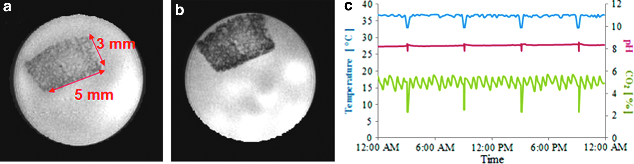
Preliminary results of a smart incubator prototype using human mesenchymal stem cells (hMSC) and a gelatin scaffold. Axial magnetic resonance (MR) imaging magnitude images of hMSC derived TE bone gelatin-based construct at week 1
Following the feasibility study, a protein silk-based TE bone construct was grown in the e-incubator for 4 weeks. Daily MR magnitude images are presented in Figure 3a. The corresponding daily acquired MR parameters, including T1 and T2 relaxation times and ADC are presented in Figure 3b. Following 4 weeks of culturing inside the magnet, cell viability inside the construct was confirmed using a scanning laser confocal microscopy for both the e-incubator and the control incubator tissues. The live–dead staining assay was used to label the viability of the hMSCs. Calcein-AM dye stained live cells green, and ethidium homodimer dye stained dead cells red. Confocal micrographs showed that the majority of cells for all groups were alive and visible with equivalent staining of live–dead cells in the osteogenic groups for the constructs grown in both the incubator and e-incubator, as shown in Figure 3c.
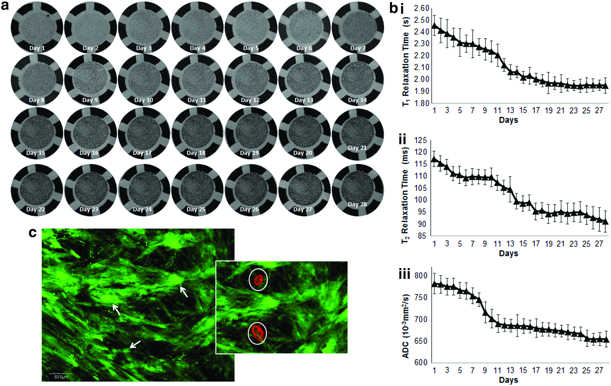
Culturing tissue-engineered bone for 4 weeks in the e-incubator.
The T2 relaxation times reduced from 118 ms on week 0 to 90 ms on week 4 (20% reduction), which was notably different than the results shown for gelatin-based TE bone measured previously. 19 These results initiated a comparison study between gelatin- and silk-based TE bone constructs. The culture chamber was modified to hold two constructs grown simultaneously in the e-incubator. Sample MR magnitude images are shown in Figure 4a. The corresponding daily measured MR parameters are presented in Figure 4b. There was only a significant difference between the measured T2 times between the two TE bone constructs (reduced from 117 ms on week 0 for both constructs to 95 ms and 60 ms for gelatin- and silk-based constructs, respectively). Finally at the end of the 4 weeks culture period, comparative histology for the gelatin and silk constructs grown in a standard incubator and the e-incubator was performed as shown in Figure 4c. The histological slides of both groups grown in the e-incubator and incubator were similar with a lightly increased mineralization for the e-incubator group over the incubator group as demonstrated by the larger number of black stains on the von Kossa slides.

Comparing the development of two tissue-engineered bone constructs grown simultaneously in the e-incubator.
Discussion
This study demonstrates the feasibility of growing tissue-engineered constructs inside the e-incubator while continuously monitoring and assessing growth through MRI and using different scaffolds and culturing methods. Importantly, the electronics of the e-incubator do not reduce the quality of the MRI data collected. In gelatin-based constructs, osteogenesis reduces the values for the T2-relaxation time by 60% due to ECM mineralization. The T2 values are correlated with osteogenic markers, including ALP activity in a previous study. 19 For the gelatin-based TE bone, the T2 was ∼20 ms at the beginning of tissue culture and reduced to ∼65 ms after 4 weeks of culture. In a previous study measuring T2 relaxation time, the T2 values reduced from 67 to 24 ms (∼60% for both methods), reduced measured values are due to the stronger magnetic field (11.74 T compared to 9.4 T), which reduces the measures T2 relaxation times.
However, the previous study was performed at discrete time points where constructs were sacrificed weekly. In our study, the e-incubator offers prolonged assessment of the same construct, which reduces data inconsistency and scattering due to sampling and dramatically reduces statistical power during hypothesis testing. Importantly, the ability to conduct continuous MRI assessment is expected to allow for the investigation of different MRI contrast mechanisms (e.g., mechanical measurement, diffusion, spectroscopy, MT ratio, etc.) and link these contrast mechanisms to the structure, composition, and function of tissue-engineered constructs. Having such capability has the potential to speed the translation of tissue-engineered products to the clinic. Additionally, such a device can provide critical clinical applications because it offers the opportunity for an intervention. For example, changing the culture environment through the replacement of growth medium or the introduction of mechanical forces through shear flow is highly feasible.
To study the effect of scaffold type on osteogenesis, we cultured osteogenic constructs in both silk- (∼500 μm pores) and gelatin- (∼250 μm pores) based scaffolds simultaneously in an e-incubator study for 4 weeks. Only the T2 value was different between the two constructs. The T2 was selected as an indicative MRI parameter and it was previously correlated with ALP activity. 19 The T2 was ∼120 ms for both constructs at the beginning of tissue culture and reduced to ∼90 ms for the silk-based construct and 65 ms for the gelatin-based construct. We concluded from this study that MRI parameters are dependent on scaffold type, primarily due to the variation in porosity. This can also be seen on the histological slides where even though bigger chunks of black stains, indicating mineral deposition, can be noticed on the silk scaffolds, higher deposited quantities can be noticed on the gelatin scaffolds.
The detailed imaging assessment technique is expected to provide a basis for creating high-quality, tissue-engineered constructs by nondestructively identifying molecular fingerprints in constructs and selecting suitable constructs with the osteogenic phenotype for implantation. Throughout the culture period, certain molecular markers are expected to be expressed along with osteogenic differentiation in MSC-derived tissue-engineered bone constructs cultured in the e-incubator. For example, OPN expresses in the early stage of developing bone cells before mineralization or OCN expression. 22 Therefore, future studies can be used to correlate MR findings with different osteogenic markers.
Limitations of the e-incubator include the physical regulatory effects of magnetic fields (static and gradients) on cells. It is possible that the high-field MR will influence the development of constructs if the tissues are constantly retained inside the MRI scanner; the physical regulatory effects of MR (strong magnetic field) on cells are not well understood. Similarly, one particular study reported that magnetic and electrical fields may alter osteoblastic proliferation and differentiation. 23 In future studies, if the growth of tissue-engineered bone is affected, then the e-incubator should only be placed inside the magnet during imaging sessions. On the other hand, if the presence of the magnetic field and alternating imaging gradients affects osteogenesis, imaging sessions duration should be optimized to enhance engineering outcome. In our future studies, we will examine the effect of the alternating magnetic field gradients, as well as compare different scaffolds. Importantly, the model of a MRI-compatible incubation system used for culturing tissue-engineered bone constructs may help create other culturing systems for other biological tissues such as tissue-engineered cartilage 24 and neural stem cells. 25
Integration of the e-incubator with MRI can potentially allow for the establishment of critical check points to identify osteogenic markers that confirm the stability of the phenotype and genotype before implantation. In turn, the e-incubator with MRI capability is expected to increase the success rate for tissue-engineered constructs through its ability to filter deficient constructs. This is particularly applicable in the ability of the e-incubator to help monitor and steer tissue-engineered bone constructs designed for unique needs of individual patients. Overall, this application has the potential to advance tissue-engineered bone techniques to clinical practice. Furthermore, while bone is used as a model system, the e-incubator itself is expected to have applications in a range of tissue-engineered constructs, including skin, organ tissue, and even tumorigenesis and cancer treatment.
The increasing use of bioreactors in tissue engineering indicates that control and manipulation of the culture environment becomes as important as the choice of cell or scaffold. Future design should incorporate physiological mechanical stress into the e-incubator system to create a bioreactor for bone TE. Perfusion flow and micromechanical ultrasound stress can both be used to transform the e-incubator to an MR compatible bioreactor.26,27 The e-incubator can be integrated with multiple imaging modalities, thus providing different contrast mechanisms and spatial resolution. For example, the e-incubator has the potential to improve our understanding of tumorigenesis by providing continuous assessment of cellular to organ levels during this process. Similarly, as the e-incubator could be used to continuously assess therapeutic efficacy. Thus, the e-incubator has the potential to transform practices in multiple biomedical sciences ranging from tissue engineering and regenerative medicine to cancer research.
Footnotes
Acknowledgments
The authors thank Dr. David Kaplan and the Tissue Engineering Resource Center (TERC) at Tufts University for the donation of silk scaffolds, NIH (P41 EB002520, Tissue Engineering Resource Center). Furthermore, the authors acknowledge the support of the Nebraska Stem Cell Proposal (Stem Cell 2013-07). The authors also thank Melody Montgomery at the University of Nebraska Medical Center (UNMC) Research Editorial Office for the professional help in editing this article.
Disclosure Statement
No competing financial interests exist.
References
Supplementary Material
Please find the following supplemental material available below.
For Open Access articles published under a Creative Commons License, all supplemental material carries the same license as the article it is associated with.
For non-Open Access articles published, all supplemental material carries a non-exclusive license, and permission requests for re-use of supplemental material or any part of supplemental material shall be sent directly to the copyright owner as specified in the copyright notice associated with the article.