




Abstract
Cell seeding in a biomaterial is an important process for tissue engineering applications. It helps to modulate tissue formation or to control initial conditions for mechanobiological studies. The compression release-induced suction (CRIS) seeding technique leads to active infiltration of the cell suspension toward the central region of the scaffold. Its effectiveness, however, may significantly vary depending on several controlling factors such as the rate of loading and unloading or scaffold architecture. We utilized a 2D axisymmetric finite element model to numerically evaluate the influence of a seeding loading regime on suction pressure and infiltration velocity of the cell suspension. The in vitro application of optimized CRIS seeding obtained from simulation showed significant effectiveness over a static seeding method. As simulation results predicted, the permeability of the scaffold directly influenced CRIS seeding effectiveness in vitro. By supplementing an optimized CRIS loading regime with slow rotation after seeding treatment, cell distribution through thickness was improved especially for scaffolds showing low permeability. Finally, we systematically analyzed the relative importance of permeability, thickness, or coating on cell seeding efficiency and uniformity using a full factorial design of experiments. We observed that permeability has a higher impact on the CRIS seeding than scaffold coating and thickness.
Introduction
C
Several static or dynamic methods have been developed for cell seeding. For the static method, the most used technique is based on surface pipetting and depends mainly on gravity for infiltration of cells inside tortuous pores of the scaffold. 5 For the dynamic seeding method, an external force is applied to facilitate the cell penetration toward the center of the scaffold. 6 Flow perfusion,2,7 centrifugation,8,9 orbital shaking,6,10 and the spinner flask2,10 are the most utilized techniques in dynamic cell seeding methods. These studies have shown that active motions of solution containing cells can improve cell distribution inside the scaffold in comparison with static methods.
Among different dynamic seeding methods, the compression release-induced suction (CRIS) has been reported as a promising approach for cartilage TE. 11 Since most of the bioreactors in cartilage biotechnology are based on compression loading regime, 12 the CRIS could be easily adapted from existing setups. By applying a compression followed by an unloading to a porous scaffold, the solution around the scaffold containing cells is infiltrated toward the central region of the scaffold. However, even for this mechanism of induced driving force, the seeding outcome may significantly vary depending on parameters such as the rate of loading and unloading, the scaffold's permeability, or the cell–scaffold interface. In a systematic approach, the cell seeding efficiency (CSE) and uniformity should be evaluated for the contributing factors in their pertinent range. This can be accomplished by determining the role of scaffold-related characteristics on seeding process while controlling cell infiltration force dynamics.
In this study, we first simulated CRIS by a 2D axisymmetric poroelastic finite element (FE) model. A what-if analysis was performed to find best parameters of the CRIS seeding loading regime to induce optimum medium infiltration. Cell seeding was then experimentally implemented according to the best loading regimes obtained from numerical calculations. To enhance cell distribution in the scaffold, we further evaluated the effect of an after seeding treatment (AST) during reswelling time. Finally, to obtain a more profound insight into the proposed seeding process, the relative contribution of the scaffold's permeability, thickness, and coating was evaluated using a full factorial design (FFD) of experiments.
Materials and Methods
Scaffold fabrication and preparation
Macroporous scaffolds of poly 2-hydroxyethyl methacrylate crosslinked with ethylene glycol dimethacrylate were prepared by a salt leaching method as described elsewhere.13,14 We utilized fixed 35%/65% polymer-to-salt ratio with 4% and 8% crosslinker (Cr) for fine (200–250 μm) and coarse (355–500 μm) salt particles, respectively. The hydrated scaffolds were sized with an 8 mm diameter punch and a custom-made cutting tool covering 1.7–3.1 mm thickness ranges.
The scaffolds were imaged by scanning electron microscopy (SEM) before and after the CRIS loading regime. For this purpose, the hydrated scaffolds before and after optimized CRIS loading (three per group) were frozen in liquid nitrogen and the frozen samples were vacuum dried for 72 h. The samples were then coated with a layer of 30 nm gold and imaged using an XLF30-FEG instrument (FEI, Hillsboro, OR).
The characterization process of the scaffolds is reported in detail elsewhere,
14
and we used the corresponding values for our model development. In brief, we measured the equilibrium elastic modulus (Eeq) of hydrated scaffolds while applying sequential compressive strain followed by stress relaxation after each step using the Instron uniaxial testing machine (Instron E3000; Norwood, MA).
15
For the Poisson ratio (
A novel custom-made setup was designed with step-wise spacer for strain-dependent permeability characterization of the scaffold based on Darcy's law. Porosity was directly calculated by measuring the volume and mass of the hydrated scaffolds as well as its dried state mass.
Before the seeding process, sterilization was carried out by autoclaving 200 mL bottles of phosphate-buffered saline (PBS) containing the scaffolds. Human plasma fibronectin (HPFN) (Sigma Aldrich, St. Louis, MO) was used for coating the scaffolds to evaluate the cell–scaffold interface effect on seeding efficiency and uniformity. Scaffolds were coated in a 48-well plate containing 2.2 μL/mm3 of coating solution (25 μg/mL) while mildly agitating (10 Hz) for 1 h after three manual compressions. Thereafter, they were incubated at 4°C overnight and washed three times with PBS before using in seeding experiments. Successful adsorption of HPFN to the scaffolds was confirmed by immunohistochemistry (data not shown). 13
Simulation of CRIS seeding
To numerically calculate time-dependent induced pressure gradient and medium infiltration caused by compression/decompression of the scaffold, we developed a poroelastic FE model based on Biot's theory 16 using COMSOL Multiphysics software (Burlington, MA). After the mesh convergence study, a what-if analysis was performed on parameters of seeding loading regime in different case studies to understand the influence of loading/unloading rates, delay time, and compressive strain on the induced suction pressure and velocity fields inside the scaffold.
In the model, the 2D axisymmetric cross section of the cylindrical scaffold having 3 mm thickness and 4 mm radius was divided into quadrilateral elements as illustrated in Figure 1a. We assumed isotropic mechanical behavior for the two types of scaffolds. Corresponding measured mean values (see Nasrollahzadeh and Pioletti
14
for detail) given in Table 1 were utilized for each scaffold model, while considering Biot–Willis coefficient of 1 for both scaffolds. The strain-dependent permeability (kɛ) of the scaffold was implemented in the model using a curve-fitted expression to the measured data up to 35% strain. In addition, the porosity (

Modeling of CRIS loading regime:
Cr, crosslinker.
To simulate the seeding working mechanism, a prescribed displacement according to the loading regime scheme (Fig. 1b) was applied on the top boundary of the model. The loading regime was expressed by a combination of two smoothed falling and rising ramp functions having parametric starting points and ramp rates.
A zero pressure (pf = 0) boundary condition was assigned on the outer edge (r = 4 mm) of the axisymmetric model during the time of the simulation to allow exchange of the fluid phase. A time-dependent boundary condition for the pressure of the top part (z = 3 mm) was assigned by using a smoothed step function to reflect the effect of plunger separation at the end of the unloading step, allowing fluid infiltration from the top boundary. The frictionless impermeable roller boundary condition was applied for the bottom boundary (z = 0) of the model.
Cell culture
Human epiphyseal chondroprogenitor cells were prepared as described elsewhere,
18
and distributed in standard polystyrene tissue culture flasks (75 cm2) for monolayer expansion. Cell culture medium (CCM) was made from Dulbecco's modified Eagle's medium with
Cell seeding implementation and AST
In vitro CRIS cell seeding was performed using a custom-made setup compatible with an uniaxial testing machine (Instron E3000) as shown in Figure 2a. The scaffolds were placed in cylinders of 11 mm diameter and 10 mm height. Then 2.6 μL/mm3 of cell suspension (5 × 10⁶ cells/mL) was pipetted onto the scaffolds placed inside the cylinders. Each cylinder was covered with a cap equipped with a piston to ensure sterile conditions under the loading machine (Fig. 2b). The scaffolds were subjected to predefined seeding loading regime obtained from the simulation and lasting for five cycles. Control static seeding was also conducted by means of surface pipetting on preconditioned scaffolds (after 24 h recovery).

In vitro cell seeding:
We supplemented the CRIS technique by a dynamic AST and compared it with a static condition. After CRIS seeding, we used a dynamic slow rotation AST 19 by employing the rotating plate of a peristaltic pump (Pump P-1; Pharmacia Biotech, Inc., NJ). For this purpose, seeded scaffolds were located in the middle of the 1.5 mL Eppendorf tubes, and remaining cell suspension in the seeding cylinder was pipetted on the top surface of the scaffold inside the Eppendorf tube.
Next, the Eppendorf tubes were rotated (10 rpm) inside a standard incubator (Fig. 2c) for two periods, each lasting 1 h. Between two periods of rotation, suspended scaffolds inside Eppendorf tubes were inverted. After this step, cell-inoculated scaffolds were transferred to 48-well plates without CCM and incubated for 45 min to ensure cell attachment. Then, 1 mL fresh CCM was added to each well and seeded scaffolds were evaluated after overnight incubation.
Experimental design to identify contributing factors to cell seeding
To evaluate the relative importance of scaffold permeability, coating and thickness in CSE, and distribution, a systematic experimental design was carried out. The range of studied factors was selected in such a way to cover an anticipated application for functional TE. We performed a FFD with eight experiments (each triplicate) for this analysis as described in detail elsewhere.
20
In brief, the linear model with interaction according to Equation (1) was chosen to fit the experimental observations.
where
Cell seeding assessment
We measured CSE and distribution metric (DM) to evaluate the seeding technique. The CSE is defined as the percentage of cells attached to the scaffold versus the initial number of cells used for the seeding.2,11 The attached number of cells was determined by counting the number of remaining cells from the medium outside the scaffold and subtracting that value from the number of initial cells used for seeding. To determine the DM, seeded scaffolds were cut in half: one half was used for the quantitative and one half for the qualitative distribution measurements (Fig. 3). For the quantitative cell distribution evaluation, 3D CellTiter Glo assay (Promega Corporation, Madison, WI) was used according to manufacturer's instructions.
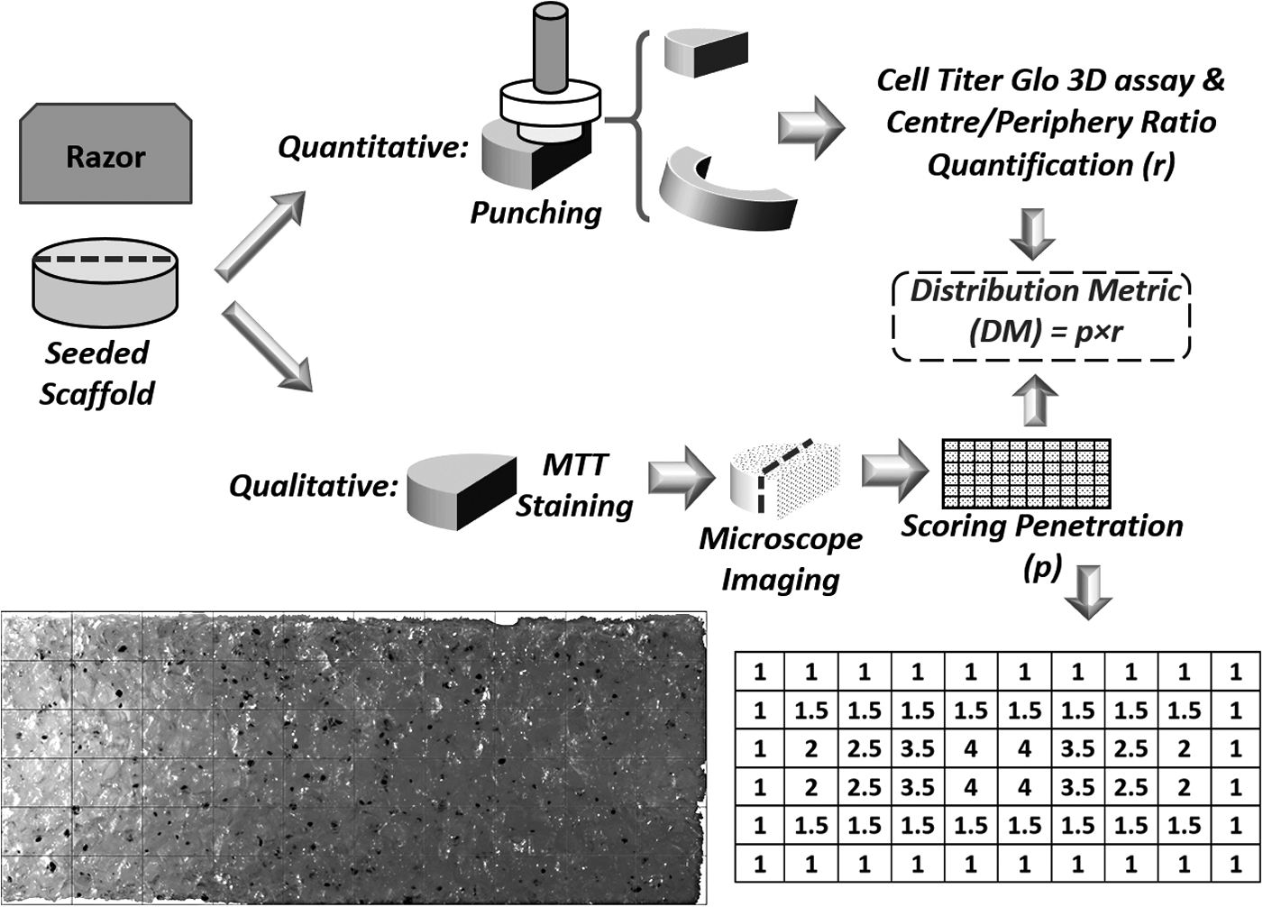
Schematic procedure of DM evaluation. DM, distribution metric.
In brief, a 5 mm punch was used to separate the core from the periphery and assay results in each section were recorded using a Wallac 1420 VICTOR 2 multilabel plate reader (Wallac Oy, Turku, Finland). The relative distribution of cells in the central to the periphery sections was defined as the ratio of normalized values by weight of sections for each scaffold (maximum value 1). For the qualitative cell distribution evaluation, the second half of the seeded scaffold was labeled with MTT cell proliferation reagent (Roche Corporation, Indianapolis, IN) to observe the cell distribution visually.
After staining according to manufacturer's instructions, three images were captured from each scaffold from top surface, bottom surface, and perpendicular cross section of the scaffold using a Stereomicroscope (LEICA MZ 16 1FA). The cross section image was manually image processed using ImageJ (NIH) software for cell penetration. For this purpose, the cross section of the scaffold was gridded to 10 × 6 partitions with predefined scores as depicted in Figure 3. The penetration score was calculated over the whole grid for each seeded scaffold and divided by 100, which provides the score of an ideal case. The qualitative penetration score was then multiplied by the obtained value for the 3D CellTiter Glo assay as the weighting coefficient to result in the DM.
We also performed live/dead staining of cell-seeded scaffolds with R37601 sensitive two-color fluorescence cell imaging kit (Molecular Probes) to assess cell viability. For this purpose, after staining the samples with mixed live and dead dyes (as provided in the kit diluted 2 × with PBS) for 20 min at 25°C, the samples were washed three times with PBS. Thereafter, green (live) and red (dead) florescence images were taken at wavelengths adjusted for fluorophores of interest by confocal microscopy (LEICA TCS SP8) with a 20 × objective and analyzed with ImageJ.
Statistical analysis
Student's t-test was used to compare DM values between static seeding and optimized CRIS seeding followed either by static or dynamic ASTs (n = 3). Significant factors for DM and CSE values in FFD were identified by a half-normal probability plot to distinguish standing out effects, which cannot be because of experimental variation. 21 Moreover, analysis of variance (ANOVA, F-test) was performed with p-value of 0.05 to determine significant half-effects and interactions.
Results
Scaffold morphology before and after CRIS loading
SEM was employed to compare the scaffold morphology before and after CRIS loading regime. As illustrated in Figure 4, there is no significant difference in pore size and pores orientation for the two types of scaffolds before (left column images) and after CRIS loading (right column images). The pore size distributions were between 120 and 240 μm for 4% Cr density and fine pore scaffolds and 220–400 μm for 8% Cr density and coarse pore scaffolds. Yet, in higher magnification images, we could observe a few more microfissures inside the pores after loading that can slightly increase pores fenestration of scaffolds. Since the applied strain is less than the plastic deformation limit, the scaffolds exhibit shape recovery after unloading. However, even if we could not see significant morphological changes, the macromolecular network of the polymeric scaffold can potentially experience deformation-induced bond rupture, 22 rearrangement, and disentanglement 23 according to “Mulins effect” 24 after CRIS loading.
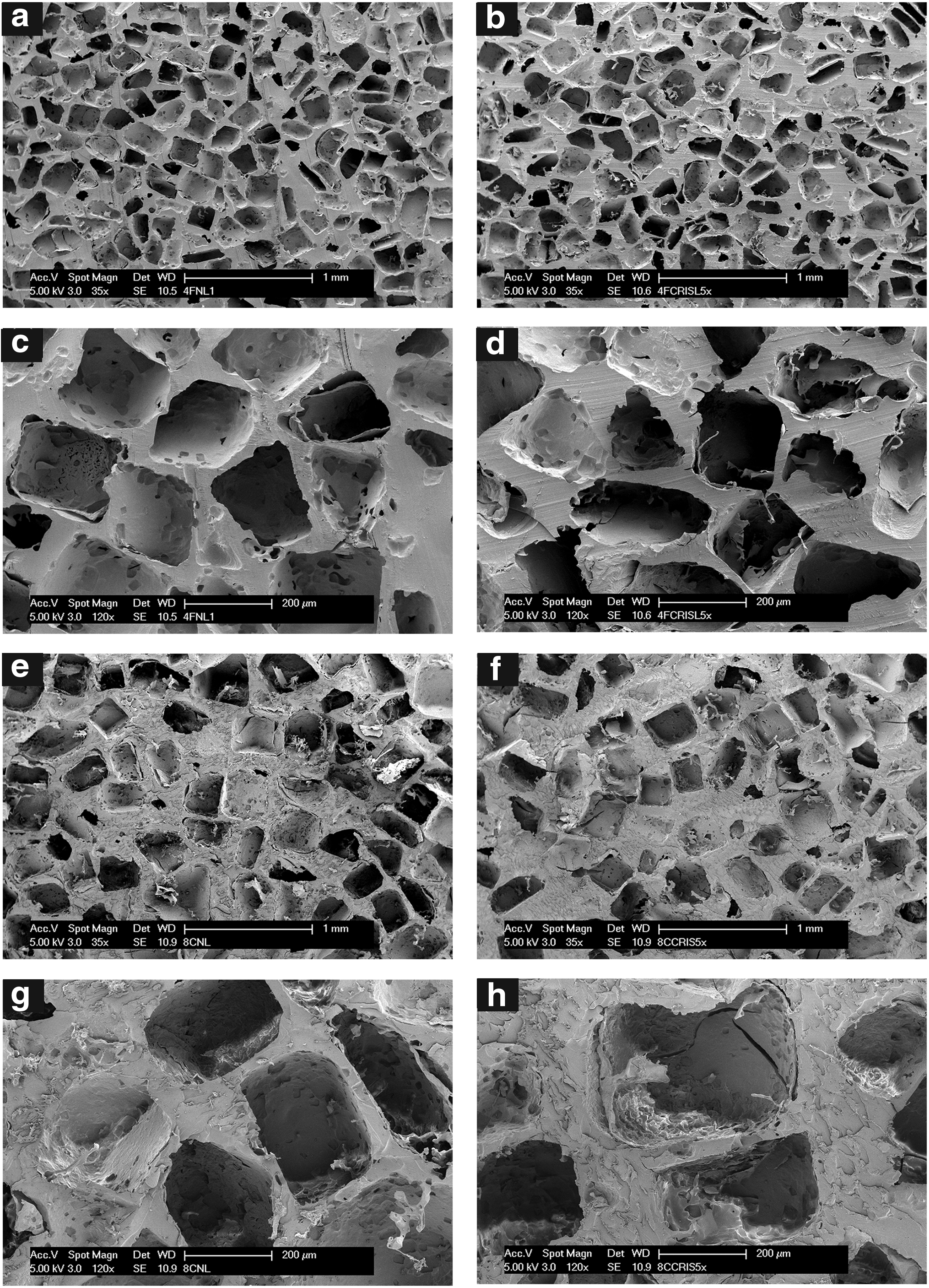
Scanning electron microscopy images before
Simulated CRIS seeding loading regime
We derived the average suction pressure and the infiltration velocity of the 2D axisymmetric surface over the simulation time and compared their maximum values in a number of case studies. Derived values for some cases are reported in Table 2 to elaborate the conducted what-if analysis. For better illustration of the induced suction pressure and velocity fields, the rainbow and arrow surface plots are combined and shown in Figure 5 at the middle and end of unloading step for the third case study. As can be seen, the medium infiltration is dominant at the outer edges of the cylindrical scaffold for both types of scaffolds. Obviously, the medium infiltration is considerably shallower for fine pore size scaffold with low permeability.

Graphical illustration of suction pressure (rainbow map) and velocity fields (arrows) inside permeable scaffolds
3, 5, and 6. Case 3 (bold) resulted in the best suction pressure and infiltration velocity, irrespective of scaffold type.
As anticipated, our simulation showed that faster unloading and larger strain enhanced medium suction into the scaffold. This can be verified for the role of unloading rate by comparing induced suction pressure and medium infiltration velocity in cases 1–6 and 7–10 for two types of scaffolds with different mechanical and morphological characteristics. Likewise, the improving effect of higher compressive strain can be seen from cases 3, 5, and 6. Interestingly, although the rate of loading was not an important parameter for the permeable scaffold, it was important for scaffold showing lower permeability. Derived results from cases 1, 2 and 3, 4 revealed the significance of slow loading rate on improved infiltration velocity and suction pressure. Likewise, longer delay time leads to more effective medium suction for fine pore size scaffolds depending on loading/unloading rates. This can be clearly highlighted when comparing cases 1 and 2 or 7 and 8. The shorter the times for loading and unloading, the more pronounced is the role of time delay.
According to the CRIS simulation results, case 3 (bold) has the best seeding loading parameters, irrespective of scaffold type. This CRIS seeding would follow a slow compression loading of 0.05 mm/s until 35% strain. Then, after a 3 s delay time, an abrupt unloading of 10 mm/s causes infiltration of the CCM containing cells into the instantaneously developed empty pores.
Cell seeding and postseeding treatments
We implemented experimental cell seeding by choosing the optimized seeding regime given by the third (numerical) case, and lasting for five cycles followed by a 10 s resting period after each repetition. The considered resting time gives enough pause for passing a transient condition before starting a new cycle. Control static surface pipetting for cell seeding was also carried out on preconditioned scaffolds having the same loading history. We utilized HPFN-coated scaffolds having 2.5 mm thickness and 8 mm diameter for comparison of different seeding strategies. Distribution of MTT-stained cells is representatively shown in Figure 6 for two types of scaffolds and extracted results are displayed in Figure 7.
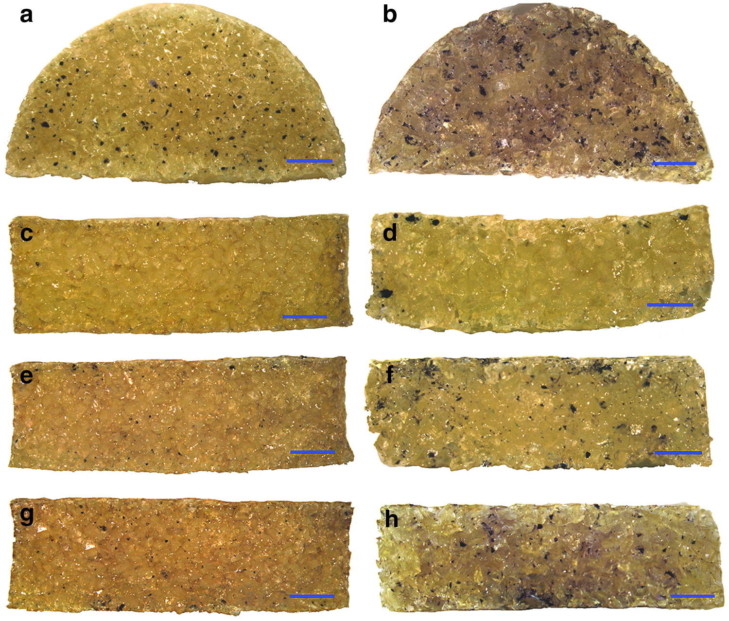
MTT-stained cells showing distribution of cells for different seeding strategies [top surface

Comparison of DM for different seeding strategies. Asterisk symbol (*) shows significant difference (Student's t-test, p < 0.05).
Despite a fairly uniform distribution on the top surface for all cases, we observed quite different patterns through cross sections of the scaffolds. It is clear that without CRIS loading regime, very poor cell penetration can be achieved irrespective of scaffold type. There is a significant difference for DM between static surface pipetting and CRIS seeding methods. As simulation results predicted, the permeability of the scaffold directly influenced CRIS seeding effectiveness. A more permeable scaffold provides a higher cell DM. In addition, although slow rotation AST slightly improved cell distribution for permeable scaffolds, its overall influence on cell penetration was significant for scaffolds showing low permeability. Moreover, live/dead staining of cell–scaffold constructs revealed very good cell survival after the proposed seeding process. Figure 8 illustrates strong signal from abundant live cells (green stain) inside two types of scaffolds after seeding, while showing only a few dead cells (red stain).
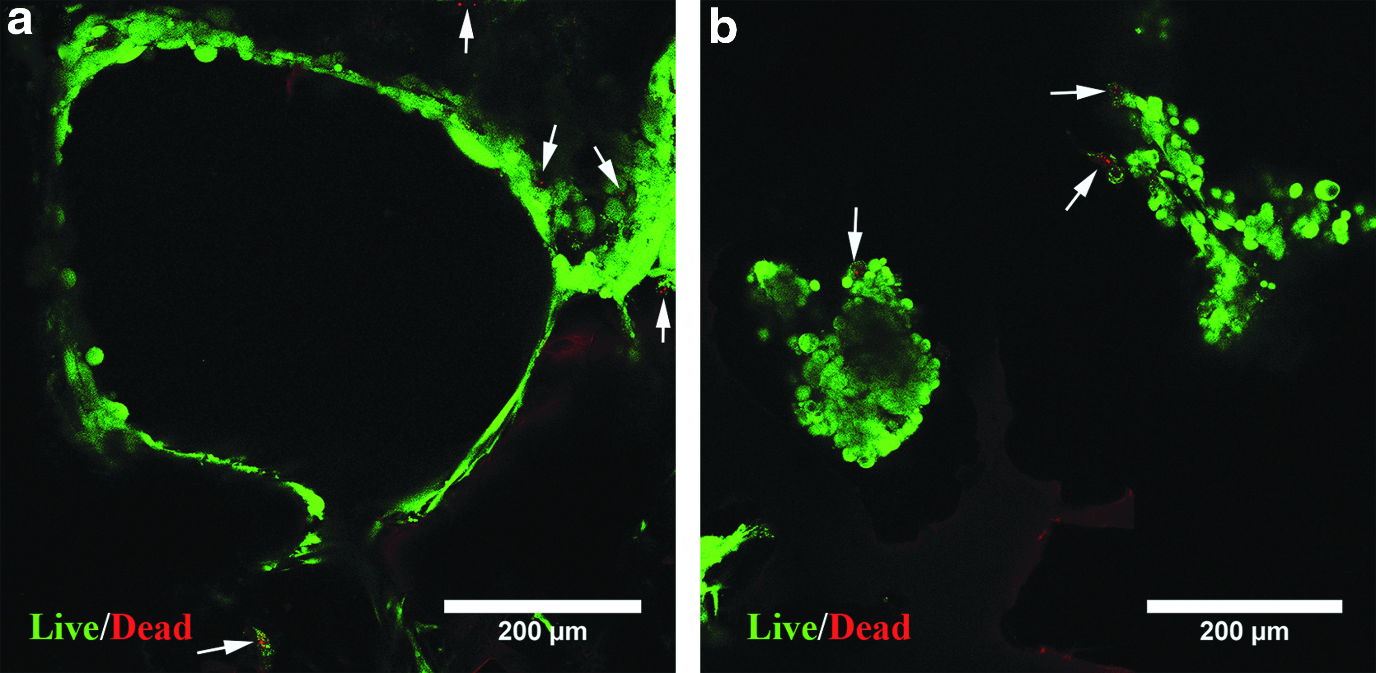
Live/dead staining of human epiphyseal chondroprogenitor cells inside coarse
Systematic analysis of main effects on seeding results
To identify the relative importance of contributing factors to seeding results, we used 8 mm diameter scaffolds having 1.7 or 3.1 mm thickness, high (k0 = O[10−12]) or low (k0 = O[10−14]) permeability, and with fibronectin coating (25 μg/mL) or no coating conditions. To standardize each factor state for the sake of computation, 20 −1 code was used for low permeability, no coating condition, and 1.7 mm thickness states, whereas high permeability, HPFN coating, and 3.1 mm thickness states were coded as +1. The coded experimental configurations and obtained responses for CSE and DM (mean and standard deviation) are reported in Table 3. Owing to the augmentation effect of dynamic AST, all experiments of this phase were accomplished by applying the slow rotation AST.
Eight experimental configurations are shown by coded values for permeability (a1), coating (a2), and thickness (a3) columns.
CSE, cell seeding efficiency; DM, distribution metric.
The results of analysis of the main effects and interactions for CSE and DM are highlighted in Figure 9. It is clear that relative importance of permeability (a1) is higher than that of coating (a2) and thickness (a3) for both responses. By looking at the extracted results, we can observe that CSE and DM responses are higher for permeable scaffolds. Our results have shown that HPFN coating improved CSE, which is a result of better cell attachment, whereas thickness had a negative effect on CSE. Given the half-normal probability plot, it can be observed that scaffold permeability, coating, and thickness were influential on CSE response, whereas just scaffold permeability affects the DM. All interactions were neither important for CSE nor for the DM response. Analysis of variance also confirmed the half-normal plot because all graphically determined contributing factors were significant (p < 0.05).
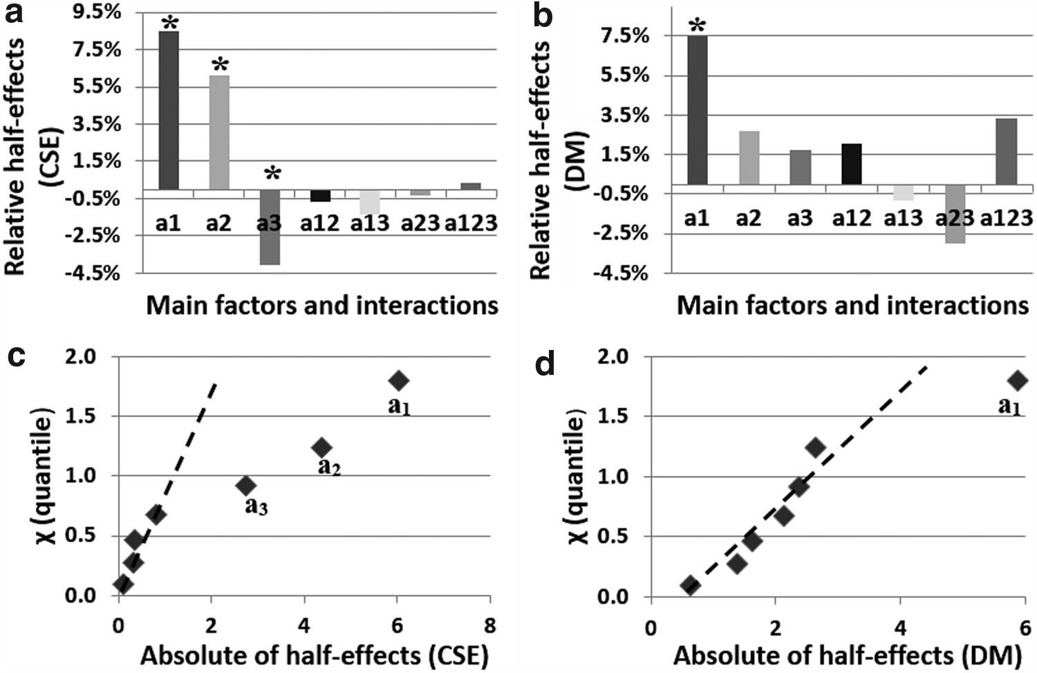
Relative half-effects and corresponding half-normal probability plot for CSE
Discussion
Preparation of a cell–3D support construct is one of the most challenging issues in functional TE, taking into consideration the demanding physiological constraints that govern scaffold design. Indeed, strictly controlled structural and mass transport properties are required for load bearing after transplantation, maintaining cell retention, viability, and differentiation.4,25,26 Accordingly, two types of scaffolds having different mechanical and morphological characteristics were employed 14 as models for evaluating the influential parameters for cell seeding. A CRIS technique was used for cell seeding inside these preformed scaffolds.
A what-if analysis was performed on parameters of seeding regime by numerical simulation of compression-induced suction in different case studies. We observed that fast unloading and large strain considerably enhanced medium suction toward the center of the scaffold for both types of scaffolds. In contrast, the influence of slow loading and delay time between loading and unloading steps was just significant for scaffolds showing low permeability.
These numerical results could be explained by the fact that permeability of a scaffold determines the ease of fluid flow inside the pores. During loading steps, fluid pressurization phenomenon occurs because of the resistance of the scaffold porous structure to the fluid seepage. For scaffolds with low permeability, release of this internal hydrostatic pressure takes release of this internal hydrostatic pressure can take longer compared to permeable scaffolds. 14 Therefore, by decreasing the loading rate or increasing the delay time, fluid pressure would have more time to be relaxed before the unloading step.
Otherwise, when the unloading step is begun, in the core region, the fluid flow is still capable of reaching outside in contrast to inward velocity field at the edge of the scaffold. This is clearly observable for rapid loading and short delay time in Figure 10 for scaffolds with low permeability. In permeable scaffolds, on the contrary, induced velocity field is unidirectional toward the central region during the unloading step regardless of rapid loading rate and short delay time.
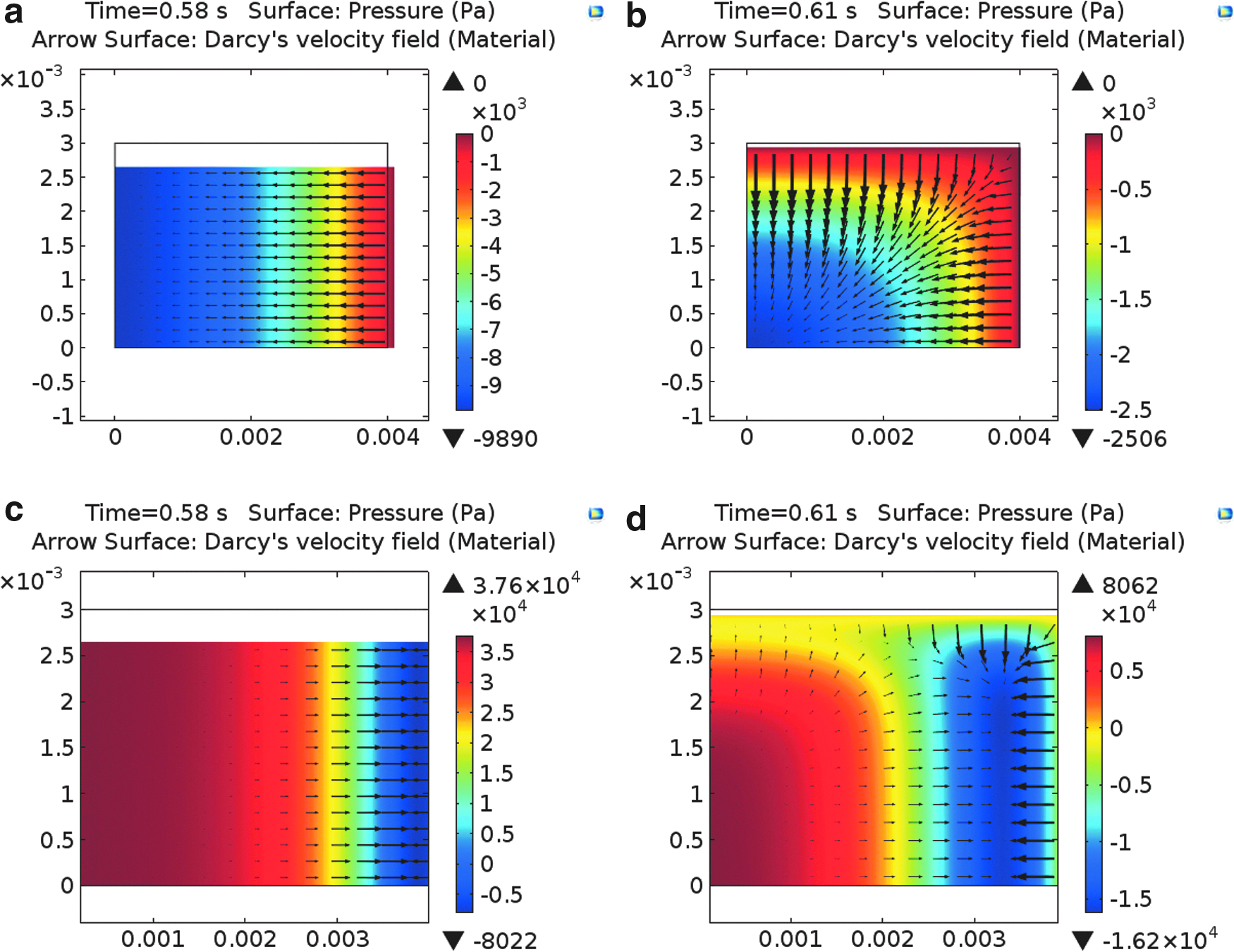
Graphical illustration of suction pressure (rainbow map) and velocity fields (arrows) during unloading step for permeable scaffolds
In addition, from the numerical results obtained, it can be observed that permeability directly affects the suction pressure and infiltration velocity for the two types of scaffolds. For example, under slow loading and rapid unloading rate conditions, the maximum induced suction pressure is twice as high in scaffolds with lower permeability. In contrast, as permeable scaffolds would show less resistance to fluid flow through the pores, even with lower suction pressure in this condition, infiltration velocity is more than four times faster than scaffolds having low permeability.
Xie et al. 11 applied compression up to 50% with the same loading and unloading rate of 5 mm/s. According to our simulation, this loading regime could be optimum for highly permeable and soft scaffolds. We showed that for scaffolds with low permeability, rapid loading rates in the CRIS seeding technique should be avoided to have optimized medium suction.
Moreover, a rapid loading rate leads to higher peak stress than a slow loading rate and this might result in damage to the scaffolds.14,27 We should also notice that the microstructure of the stiff scaffolds could be destroyed by increasing a compressive strain up to 50%. In our case, the plastic deformation of the highly crosslinked scaffolds (8% crosslinking density and coarse pores) was measured to be around 35%. Yet, our soft scaffolds with low permeability (4% crosslinker and fine pores) showed elastic deformation up to 40%.
Performed experimental cell seeding according to the optimal loading regime obtained from the simulation showed significant improvement on cell penetration compared with static surface pipetting. We also observed an enhancing role of slow rotation AST (dynamic incubation) after optimized CRIS loading regime, especially for scaffolds showing low permeability. We could explain the AST working mechanism by the hypothesis that the cell penetration in the scaffold is because of the active fluid movement inside the tortuous pores of the scaffold during the reswelling period. Apparently, after several loading–unloading steps, hydrated scaffolds had some loss of fluid inside the pores. Therefore, by providing dynamic movement of cell suspension around the scaffold after initial shallow suction, there can be an active movement of cells deep inside the scaffold compared with static incubation.
We have shown high cell viability for the optimized CRIS seeding followed by slow rotation AST. Obviously, the rate of loading and the amount of strain are important factors on transmitted stress on cells and, therefore, overall cell viability. The unloading rate should not be important on cell viability because we are releasing the maximal applied stress on cells during unloading. The peak stress in the optimum loading regime was always <1.5 MPa, which is the physiological stress in native cartilage during walking. 28 Likewise, 35% strain is not exceeding the reported physiological magnitude of dynamic strains after activity (ranging between 15% and 35%). 29
Thus, the proposed optimum loading regime is not in a nonphysiological level and would not transfer damaging forces to cells. In general, applying an external force in dynamic seeding techniques will improve cell distribution; however, the nature of this dynamic force (e.g., harsh centrifugation 9 ) might reduce cell viability. Evidently, the proposed CRIS with slow rotation AST, does not affect cell viability and it does enhance cell distribution within the scaffolds.
Our systematic experimental design showed the scaffold permeability (a1) is the most significant factor for both CSE and distribution compared with coating (a2) and thickness (a3). Conventionally, porosity, average pore size, and distribution of pore size are used as primary characteristic parameters of TE scaffolds, whereas interconnectivity, fenestration size, fenestration distribution, and orientation of pores are used as secondary indicative parameters of a porous structure. The difficulty of characterizing some of these parameters is the reason why it is difficult to find all of them in publications. 30 In practice, permeability is an overarching mechanical parameter encompassing the effects of all mentioned morphological features. Therefore, permeability as a robust quantitative determinant has been suggested for evaluating porous structures.30,31 Accordingly, we selected permeability to study influence of morphological characteristics of the scaffold (e.g., pore size, interconnectivity, and porosity) on cell infiltration.
The considered range for permeability (O[10−14] < k0 < O[10−12]) was wide enough to reflect its role considering the reported values in the literature 31 for functional TE applications. In correlation with the study of Melchels et al., 4 our results indicated direct influence of permeability on CSE and uniformity. Obviously, the more permeable the scaffold is, the easier the solute transport is within the structure and accordingly cell infiltration.
On one hand, the literature has clearly reported the effective role of higher permeability and larger pore size on vascularization of scaffolds and bone in-growth in the field of bone TE.32,33 On the other hand, it has been shown that cartilaginous matrix synthesis by chondrocytes is enhanced inside scaffolds having smaller pore size and lower permeability (mimicking more similarly in vivo cartilage environment).26,34 Taken together, a trade-off between seeding outcome and chondrogenesis should be considered for cartilage TE when designing scaffold permeability, whereas this is not the case for osteogenesis in bone TE.
Although scaffold coating was also contributing to CSE, it has had a minor effect on distribution of cells within scaffolds. Different concentrations of fibronectin have been used in the literature for coating scaffolds mostly between 10 and 20 μg/mL.13,35,36 We used 25 μg/mL to clearly differentiate the coating and no coating conditions. Since fibronectin has the arginylglycylaspartic acid (RGD, arginine–glycine–aspartic acid) cell recognition sequence, it enhances functionality of the scaffolds and cell–scaffold interface interaction. 37 In fact, scaffold coating with fibronectin modulates binding sites for cell attachment; therefore, it is expected to influence the CSE. Interestingly, previous studies also demonstrated that fibronectin-coated scaffolds facilitate cell proliferation as well as neotissue formation, supporting use of bioactive scaffolds for TE application.35,38
Increasing scaffold thickness reduced the CSE response, whereas it had negligible effect on the DM. The scaffold thickness range (1.7 and 3.1 mm) used in this study reflected the anticipated application, which is for human knee cartilage where the thickness is roughly between 2 and 3 mm. 39 Controlling the cell distribution in the scaffold is an important aspect for clinical application, where a different scaffold thickness might be required based on lesion location. Undoubtedly, we can maintain the concentration of cells by initially using higher number of cells for thicker scaffolds to compensate its negative influence on CSE.
One limitation of the performed numerical study was considering specific isotropic and homogeneous mechanical properties for the scaffold. Although this was appropriate to particularly study the role of different parameters, one can imagine a numerical analysis of the scaffold mimicking the anisotropic poroviscoelastic cartilage having depth-dependent structural heterogeneity. Experimentally, we just investigated the influence of slow rotation AST during reswelling time over static incubation. Owing to expected enhancing role of dynamic conditions such as orbital shaking, one could have compared different dynamic ASTs and rank them accordingly. The effect of coating concentration on seeding results should also be studied. It could be interesting to find the minimum and maximum coating concentration to detect the threshold and saturation point.
Improved spatial distribution in dynamic seeding methods compared with poor uniformity of static seeding highlights the role of external force to actively control medium infiltration during the seeding process. This external driving force was provided in our seeding method by the optimized CRIS seeding loading regime supplemented with slow rotation AST during reswelling time of the scaffold. Permeability, coating, and thickness of scaffolds contribute to the seeding outcome regardless of the seeding strategy. However, we have shown that the role of permeability is more pronounced than that of coating and thickness of the scaffolds in the CRIS seeding method.
In conclusion, this study presents a systematic analysis of scaffold mechanical and morphological characteristics, geometry, and surface functionality with regard to effectiveness of a seeding strategy. This approach helps to identify the key parameters affecting the seeding process in cell–scaffold-based TE. In particular, controlling cell seeding in scaffolds is important in developing TE products, which have to be compliant with regulatory aspects necessitating reproducible and consistent procedures.
Footnotes
Acknowledgments
We thank Sandra Jaccoud for her precious technical support. We also appreciate the advice of Dr. Jean Marie Furbringer for design and analysis of systematic experiments. This work was supported by the Swiss National Science Foundation (No. 310030_149969/1).
Disclosure Statement
No competing financial interests exist.