




Abstract
This article describes fabrication of a customizable bioreactor, which comprises a perfusion system and coverslip-based tissue culture chamber that allow centimeter-scale vascularized or otherwise canalized tissue constructs to be maintained in weeks long static and/or perfusion culture at an exceptionally low cost, with intermittent live imaging and media sampling capabilities. The perfusion system includes a reusable polydimethylsiloxane (PDMS) lid generated from a three-dimensional (3D)-printed poly-lactic acid (PLA) mold and several lengths of perfusion tubing. The coverslip tissue culture chamber includes PDMS components built with 3D-printed PLA molds, as well as 3D-printed PLA frames and glass coverslips that house perfusable hydrogel constructs. As proof of concept, we fabricated a vascularized hydrogel construct, which was subjected to static and perfusion tissue culture, as well as flow studies using fluorescent beads and widefield fluorescent microscopy. This system can be readily reproduced, promoting the advancement of tissue engineering and regenerative medicine research.
Impact statement
This bespoke bioreactor system allows weeks long (and potentially longer) culture of vascularized or otherwise canalized centimeter-scale cell containing hydrogel constructs, while also permitting live imaging during perfusion cell culture, with intermittent sampling of media for analysis. Furthermore, this system is low-cost, relying on three-dimensional-printed components using poly-lactic acid filament, and molding polydimethylsiloxane to form autoclavable chambers and lids. Using the methods and printing code described herein, other laboratories may readily replicate this system to advance their perfusion-based tissue engineering projects.
Introduction
The on-demand generation of perfusable vascular networks is a crucial goal for tissue engineers. Nearly all human cells rely on capillary diffusion for nutrient, oxygen, and waste exchange, and thus must remain within 100–200 μm from a blood vessel to survive, thereby considerably limiting the size and thickness of viable tissue grafts for surgical application. 1 De novo creation of engineered tissues with a hierarchical vasculature of coalescent vessels large enough to be reliably anastomosed using standard microsurgical technique (≥1 mm diameter) promises to revolutionize the clinical application of engineered tissues, but significant challenges remain.1–4
Perfusion systems have proven valuable in medicine and research to sustain otherwise ischemic tissues, such as donor organs for transplantation, 5 and, recently, whole pigs after recent sacrifice. 6 Perfusion systems for tissue culture have proven effective, not only for maintaining cellularized constructs, but also for generating biologically appropriate morphological changes in the neovessels, including endothelial cell elongation and actin filament alignment parallel to the direction of flow. 7 Additionally, the high shear stress (10–70 dyne/cm2) 8 producible by perfusion culture upregulates Notch1 signaling associated with arterial cell designation. 9 By generating a vascular network that coalesces into larger channels, an environment of lower shear stress is created that may encourage venous endothelial designation.8,10 Altogether, these adaptive changes support vascular network maturation in vitro.
Our laboratory has previously generated single-channel vascularized tissue constructs perfused upon microanastomosis to rodent circulation. 2 Unfortunately, perioperative thrombosis was common because of imperfections in the endothelial lining of the hydrogel, likely secondary to endothelial cell detachment from arterial shear forces, which exposed the perfused blood to the underlying collagen of the construct. 11 These suboptimal outcomes demonstrate the necessity for in vitro-generated vascular networks to mature under conditions of slowly increased perfusion shear stress, inducing luminal cells to undergo morphological changes that would allow them to withstand the forces of in vivo circulation.
Limited access to sterile perfusion culture circuits has historically been an obstacle to low-cost generation of in vitro vessels, as both large-scale bioreactors and commercially available microfluidic systems are often expensive and highly specialized. 12 Moreover, microscopic perfusion systems are rarely commercially available, leading many researchers to generate their own perfusion systems.13–17 When systems are obtainable, they are fabricated to highly specific parameters, thereby necessitating the purchase of new components for any subsequent modification. Furthermore, such perfusion systems may cost anywhere from hundreds to thousands of dollars per item. 12
Inspired by the significant cost and limited flexibility of commercially available bioreactors, we developed a perfusion system that is inexpensive to assemble and maintain. Additionally, this bioreactor permits intermittent live imaging, enabling visualization of flow patterns in situ as well as monitoring of cell viability. Herein, we describe the fabrication and perfusion culture for 14 days of vascularized hydrogel constructs cultured within this bespoke bioreactor.
Materials and Methods
Perfusion system and coverslip tissue culture chamber
Molds, frames, and supplementary pieces were created through computer-assisted design (CAD) with Fusion 360 (Autodesk), and 3D printed using fused deposition modeling (FDM) of poly-lactic acid (PLA) 1.75 mm filament (MatterHackers) on a Prusa i3 MK3S Printer (Prusa Research). PharMed BPT, 1/16ʺ ID × 1/8ʺ OD tubing (Cole-Parmer) was cut to appropriate lengths and placed into the molds after a light coating of Product of Arthur Meyerhoff (PAM) spray (ConAgra Foods) and subsequent blotting. The molds were filled with degassed polydimethylsiloxane (PDMS; Dow Corning) and cured at 150–175°F before being washed of residual PAM and assembled with necessary tubing.
Formation of the PDMS components is detailed in Supplementary Video S1. The PDMS lid was designed to cover a Petri dish with a diameter of 150 mm and a height of 20 mm and was assembled in two stages, first of the lid and then brim. For lid production, the triangular and round PDMS Petri Dish Lid Mold insets were glued into the bottom of the PDMS Petri Dish Lid Mold with a thin layer of Super Glue (Gorilla®). Then, four male and female polypropylene luer × 1/16ʺ hose barb adapters were screwed together by the luers. The two connected luers were inserted, male first, into each hole in the PLA lid mold, with a 10 mm length of Pharmed tubing placed on each barb of each male and female luer to ensure no PDMS infiltration during pouring (Fig. 1A). After coating the mold in a thin layer of PAM, the PLA lid mold was filled with degassed PDMS and cured. The triangular and circular protrusions of the lid represent its top, external surface.

For brim assembly, the cured lid was placed with protrusions facing downward into the brim frame, then a 150 × 20-mm Petri dish was centered, upside down, on the lid and weighted down with a 1 kg weight, after which PDMS was poured around the Petri dish to fill the brim mold and set (Fig. 1B). After removing the lid from the PLA mold, the rough surface on top of the lid was “glassed” with a thin layer of PDMS. Next, the 10 mm lengths of tubing were removed from the luer barb adapters. For coverslip device assembly, the PLA chamber mold was thinly coated with PAM, then the needles from a 16-gauge and a 14-gauge catheter were placed into their respective holes within the mold (14-gauge left, 16-gauge right) (Fig. 2A). The 16-gauge catheter is the “artery,” with the larger 14-gauge catheter serving as the lower resistance “vein.”

The PLA mold was filled with PDMS and cured. After removal of needles, the PDMS chamber was removed from the mold. The rough surface of the PDMS chamber created by the mold was “glassed” with PDMS as before. Next, 16-gauge and 14-gauge catheters were inserted into the mold channels until the hubs reached the chamber, hubs facing down. The catheters were trimmed to extend 2 mm into the chamber and the needles inserted into the corresponding catheters to extend 10 mm into the chamber (Fig. 2B).
Cell culture
Human aortic smooth muscle cells (HASMCs; ATCC, Manassas, VA) were transfected to express red fluorescent protein (RFP) to create RFP-HASMCs as previously described. 18 AdE4(+) HUVEC 19 (gift from Dr. Shahin Rafii), were transfected to express green fluorescent protein (GFP) using lentivirus, to create GFP-E4-ECs. RFP-HASMCs (passage 3–5) were maintained in cell culture using smooth muscle cell basal medium supplemented with smooth muscle cell mitogen (ATCC). GFP-E4-ECs were cultured using endothelial cell basal medium supplemented with endothelial growth factors. Penicillin/Streptomycin Solution (P/S; 100 × ; Corning) was added to SMC and EC media to generate a final medium with 1% vol/vol P/S. Media changes were performed every other day with cells passaged as needed.
Macrochannel formation with sacrificial Pluronic® F127
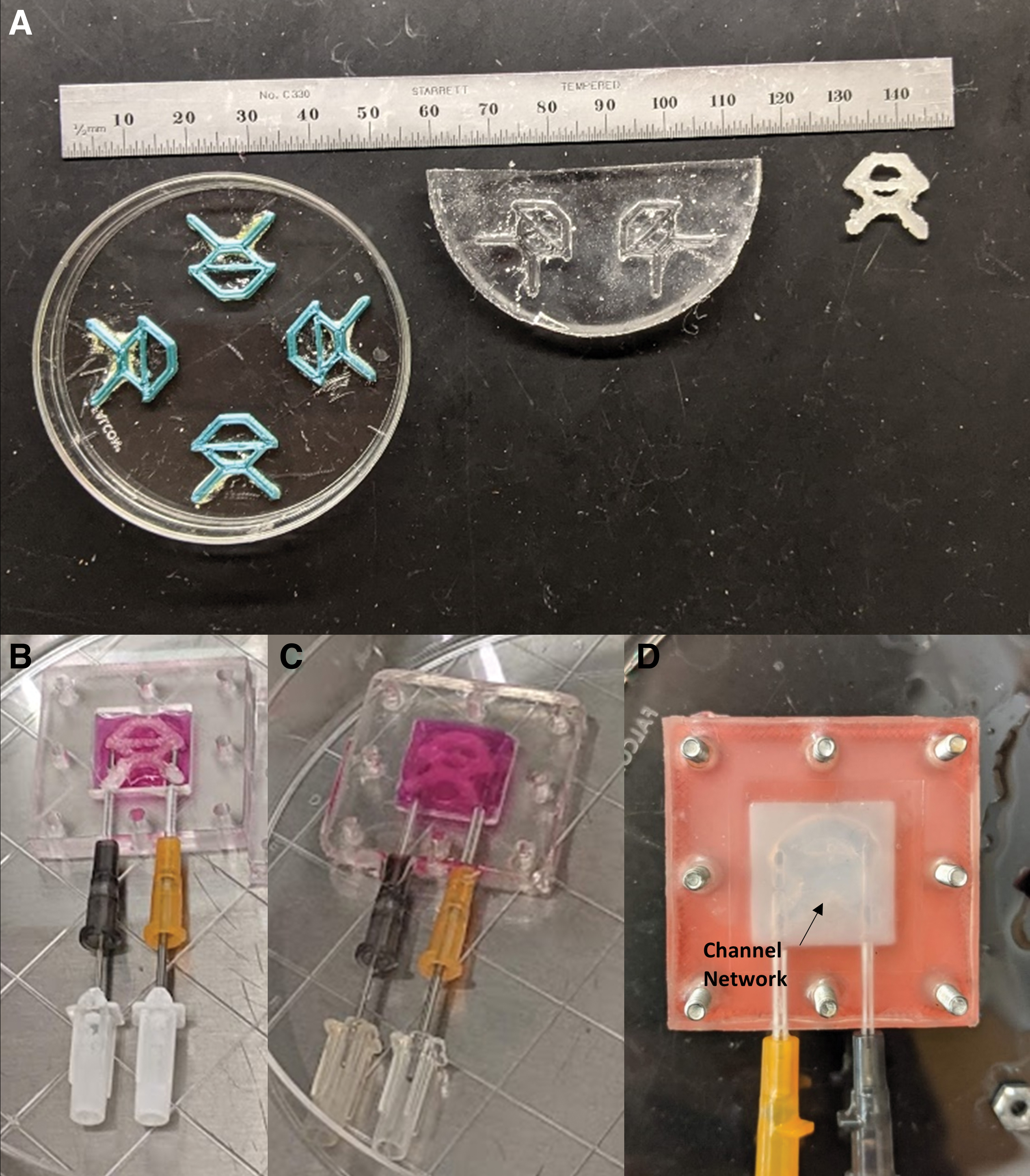
Fibers were designed with CAD using Fusion 360 (Autodesk) and 3D printed in PLA (Fig. 3A). Individual PLA fibers were glued to the bottom of a 100 × 20-mm Petri dish with a thin layer of Super Glue (Gorilla) and thinly coated with PAM (Fig. 3A). PDMS was added to the dish until the fibers were covered by 2–3 mm and allowed to set. After setting, PDMS molds were cleaned, then sprayed with PAM. Pluronic F127 powder (Sigma-Aldrich) was heated in a glass beaker on a hot plate to 130°C to induce melting, then a small drop was poured onto wax paper. The PDMS mold was placed over the drop of Pluronic and a 1 kg weight was placed on top. After 1 min, the weight was removed and the PDMS was peeled away from the Pluronic filament. Excess Pluronic was trimmed away using single-edge razor blades and 22-gauge catheters to yield sacrificial Pluronic fibers (Fig. 3A).
Hydrogel construct fabrication and seeding
Fourteen- and 16-gauge needles were inserted into their respective catheters and then the PDMS chamber was autoclaved. Pluronic fibers were sterilized through ultraviolet (UV) exposure for 30 min. Acidified type I rat tail collagen was isolated as previously described 15 and neutralized to a concentration of 1% w/v, mixed vigorously, and centrifuged at 0°C for 3 min at 2500 rpm to remove bubbles.
Neutralized collagen was pipetted into the PDMS chamber to the level of the needle tops. Next, a Pluronic fiber was sterilely placed onto the needles as seen in Figure 3B. Collagen was then dispensed to fill the chamber over the Pluronic fiber until a meniscus was formed at the top of the chamber (Fig. 3C). After collagen deposition, the device was aseptically moved to the incubator. As the collagen was allowed to crosslink for 1 h, the Pluronic fiber dissolved, generating hollow channels (Fig. 3D). The device was then returned to the biosafety cabinet and flipped “open-side” down with sterile tweezers. Fifty microliters of sterile phosphate-buffered saline (PBS; Corning) was added, and the Petri dish was returned to the incubator overnight for dissolution of residual Pluronic fiber.
The following day, HASMC-RFP (passage 3–5) was treated with 0.05% trypsin (Corning) and counted, then resuspended in SMC medium at a concentration of 5 × 10⁶ cells/mL. Using sterile tweezers to secure the chamber, the channels were flushed with several hundred microliters of PBS using a 200 μL micropipette to remove any residual Pluronic before cell seeding. The PDMS chamber was then placed into a new 150 × 20-mm Petri dish, and 200–300 μL of cell suspension (calculated interior volume of the channel) was introduced through the 16-gauge catheter, in 2–3 increments of 100 μL, using a micropipette. The Petri dish was placed back into the incubator for 30 min and the PDMS chamber was flipped 180° for another 30 min to maximize cell adhesion. A total volume of 50 mL 1:1 SMC:EC media mixture was added, and the Petri dish was returned to the incubator overnight.
The following day, the devices were transferred to new Petri dishes and channels aspirated before GFP-E4-ECs were seeded in a similar fashion at 5 × 10⁶ cells/mL, with the construct left in culture for 3 days. Construct formation and seeding are depicted in Supplementary Video S2.
Perfusion device assembly
The full perfusion system comprises several lengths of PharMed tubing (2 × 450, 1 × 100, 3 × 80, 2 × 50, 1 × 40 mm; Fig. 4), one piece of 1.65 mm ID, Blue-Blue, Standard PVC Two-Stop Peristaltic Pump Tubing (Fisherbrand™), a previously molded PDMS Petri dish lid, two Discofix® 4-way stopcocks (Braun), and several male ( × 7) and female ( × 4) polypropylene luer-1/16ʺ barb adapters, with a 0.2 μm cellulose acetate filter (VWR), as well as the coverslip chamber device. The PDMS chamber, which will remain in the incubator until assembly, a PDMS gasket, two glass 25 × 25 mm coverslips (VWR), 2 PLA frames, at least eight stainless steel 18–8 #4–40 × ¾ʺ bolts (Bolt Depot), and at least eight zinc Cr3+ #4–40 × 1/4ʺ × 3/32ʺ hex machine screw nuts (Brighton Best) are required to assemble the coverslip device (Fig. 5). Extra nuts, bolts, and coverslips were often included in the autoclave pouch to provide redundancy.

Perfusion circuit components with assembled coverslip chamber device.
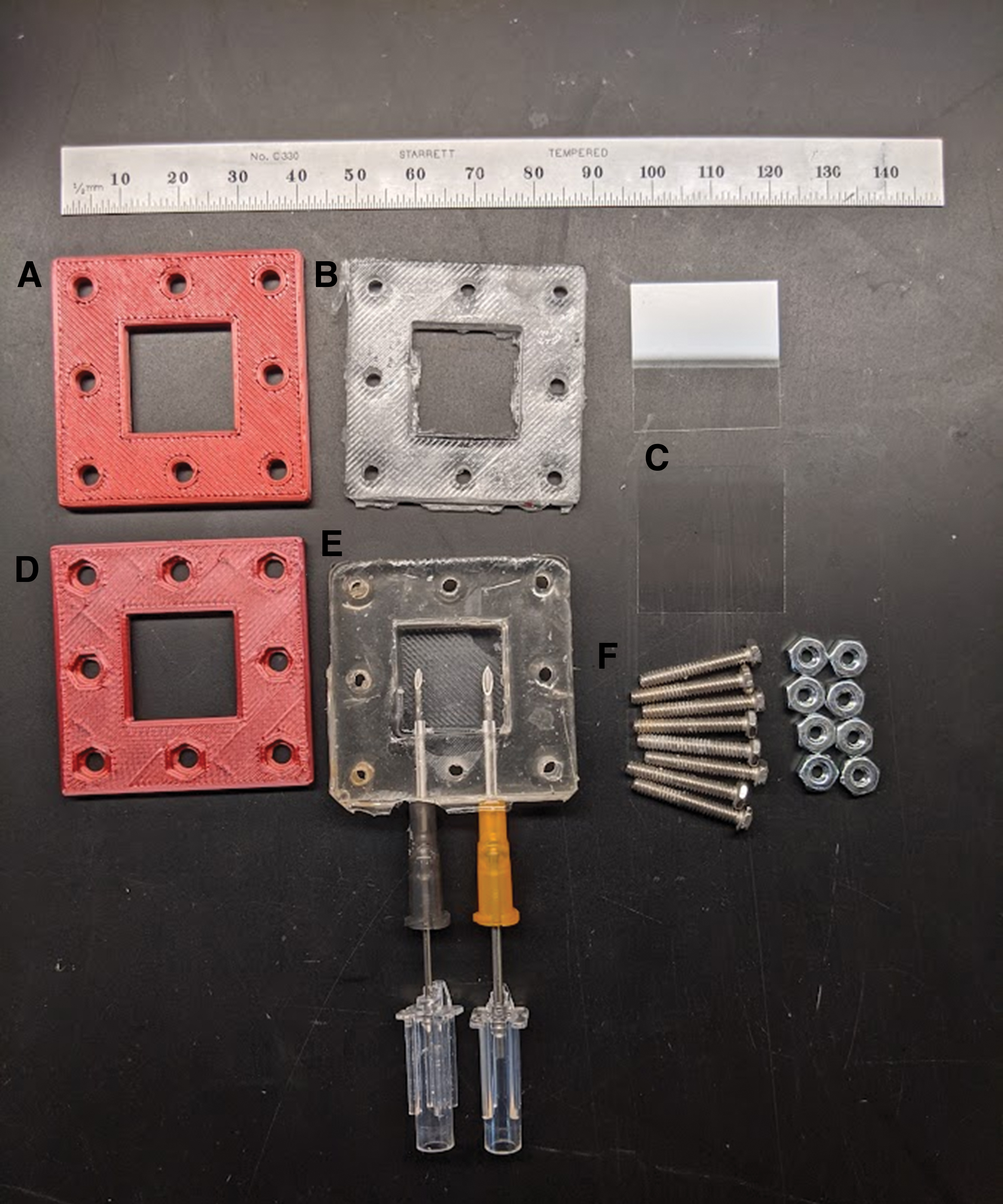
Coverslip device components.
Perfusion tubing was assembled before autoclaving by attaching one 450 mm length of PharMed Tubing to each end of the peristaltic pump tubing using two male and two female luer barb adapters. The PDMS Petri dish lid was assembled as follows: Three 80 mm lengths of PharMed tubing were attached to the external inlet, media bypass, and outlet luer barbs. One 40 mm length of PharMed tubing was attached to the external filter luer barb. Four male polypropylene luer barb adapters were inserted into the free ends of the four external tubing segments. One 100 mm length of tubing was attached to internal inlet luer barb, with a male luer barb attached to the free end. Two 50 mm lengths of tubing were attached to the internal media bypass and outlet luer barbs.
The assembled Petri dish lid, perfusion tubing, coverslips, nuts, and bolts were autoclaved together. PLA frames were cleaned with 30 min of UV sterilization per side. Additionally, a set of sterile forceps, a 5 or 10 cc syringe, a 50-mL polypropylene conical tube of sterile PBS, a sterile 0.2 μm cellulose acetate filter, and two sterile three-way manifold stopcocks were required for assembly. A schematic of the perfusion system can be seen in Figure 6.
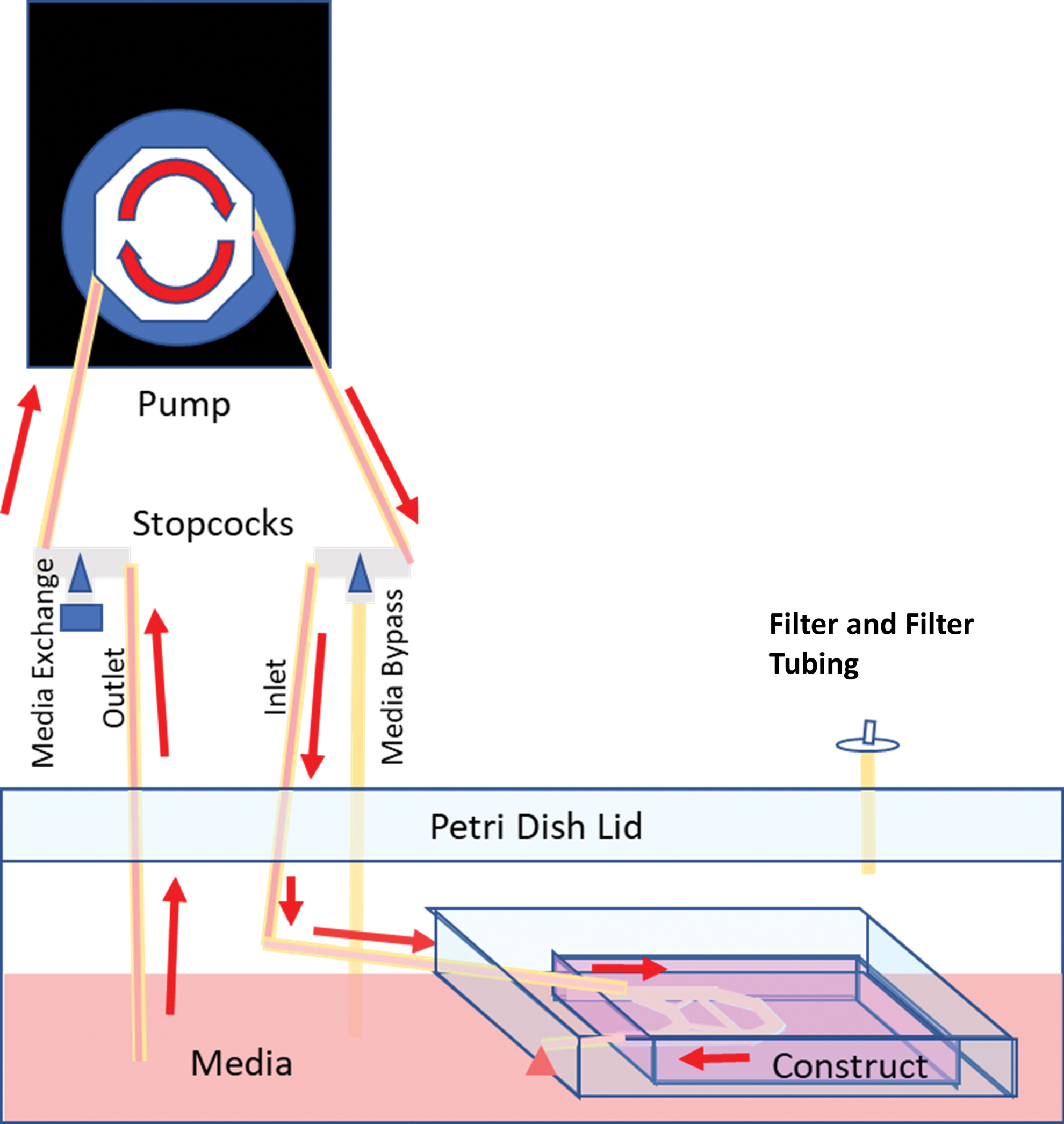
Schematic of perfusion circuit showing stopcock position during media perfusion. Media are drawn up from the Petri dish reservoir through the Petri dish lid. Media are pumped from the outlet tubing through the inlet stopcock and tubing back through the Petri dish lid, entering the inlet of the PDMS chamber and the vascular channels within the collagen construct. Media then flows out freely into the Petri dish. By adjusting the stopcock, media can be exchanged through the media exchange port on the outlet tubing. Similarly, turning the inlet stopcock enables purging of bubbles from the tubing. Color images are available online.
Assembly began with the opening of the autoclave pouch, creating a sterile surface. The 50-mL conical tube of PBS was opened, and the Petri dish containing the PDMS chamber was brought to the biosafety cabinet. Twenty milliliters of medium was removed from the Petri dish and an additional 20 mL of fresh 1:1 SMC:EC media was added. This amount can be adjusted up to the entire Petri dish volume, provided an equivalent volume is replaced. Next, the bolts were sterilely placed through the bottom frame and PDMS gasket. A coverslip was placed onto the collagen, and the bottom frame and PDMS gasket with bolts were slid into place on top of the chamber. An additional coverslip was placed on the PDMS side of the chamber, with the top frame placed over the bolts, and nuts fastened. The external end of the inlet tubing was connected to the inlet stopcock, then 5 mL of sterile PBS was injected into the tubing.
The internal end of the tubing was connected to the 16-gauge catheter of the PDMS chamber, then the external end of the media bypass tubing was connected to the inlet stopcock. The 14-gauge catheter was left open to atmospheric pressure to minimize the “venous” resistance, thereby more closely mimicking venous resistance in vivo. The other stopcock was connected to the outlet tubing, retaining the plug on its side port. The filter was attached to the filter tubing, then the three-piece perfusion tubing was attached to the inlet and outlet stopcock. The lid was raised, and the hanging PDMS chamber was carefully lowered bottom-frame down into the Petri dish with 1:1 SMC:EC media. Assembly of the full perfusion circuit is detailed in Supplementary Video S3.
The Petri dish was brought to a L/S® (Laboratory Standard) variable-speed economy drive peristaltic perfusion pump (Masterflex). The two-stop peristaltic pump tubing was attached to the pump with a L/S Small Cartridge for Multichannel Cartridge Pump Head (Masterflex) without disconnecting either end of the tubing. The stopcocks were turned to fill the tubing with media. The pump was stopped, the inlet stopcock was turned to allow flow, and the pump was set at 2 mL/min. The Hagen–Poiseuille formula (Eq. 1), which assumes steady state and laminar flow, produces an estimate of shear stress, given η, the fluid viscosity in cP; Q, the volumetric flowrate in cubic meter per second, and r, the radius of the tube in meter.
At a flowrate of 2 mL/min, and with a media viscosity of 3.3 cP, 20 the cells at the inlet of the 1.8 mm diameter inlet are exposed to roughly 2 dyne/cm2, a shear stress that is substantially less than the roughly 15 dyne/cm2 typically experienced by the arterial intima. 8 Starting with a low shear stress is standard practice in perfusion bioreactors, 21 as it induces morphological changes in luminal cells that allow for adaption to increasing shear.
After visualization of media exiting the chamber, the Petri dish was placed into the incubator, while ensuring that the internal end of the outlet tubing remained submerged. For devices maintained in static culture, perfusion tubing was not assembled; instead, plugs were placed onto the external inlet, media bypass, and outlet tubings, and the inlet tubing was not connected to the 16 g catheter of the PDMS chamber.
Media exchange
Media were changed every 3–4 days in the biosafety cabinet. A sterile 20-cc syringe was used to remove spent medium from the exchange port. Spent medium was saved for pH and glucose content analysis using pH strips (Hydrion) and an AimStrip® Plus glucometer (Germaine® Laboratories Inc.), respectively (data not shown), for comparison to fresh media, to assess for infection, and to detect detached cells. An equal amount of 1:1 SMC:EC fresh media was added through the exchange port, the perfusion tubing was reinserted into the pump cassette, and media flow was restarted through the bypass tubing to ensure bubble elimination. Flow was then restarted through the perfusion chamber at 2 mL/min.
Imaging and device fixation
Devices were imaged with an Olympus CKX31 light microscope, an Olympus IX71 Inverted Fluorescence Microscope, and confocal microscopy on a Zeiss Cell Observer SD equipped with a Photometrics Evolve 512 EMCCD camera on the Yokogawa CSU-X1 confocal scanner unit. Live imaging was performed with devices sealed in the perfusion bioreactor, with additional imaging performed after construct sacrifice.
At the time of construct sacrifice, the perfusion circuit was disconnected from the inlet of the PDMS chamber, the chamber was disassembled, and the collagen was detached from the chamber and placed into an embedding cassette and fixed in 10% formalin.
The stopcocks were discarded and the remaining assembled perfusion line was flushed with 10% bleach and allowed to sit overnight, then flushed with 70% ethanol, followed by a water rinse. The remaining circuit was then disassembled, and the pieces were allowed to dry before reassembly for future experiments. All PDMS components were thoroughly washed with soap and water and allowed to dry, then autoclaved and kept in sterile autoclave bags until use.
Flow studies
Studies to assess flow were performed on unseeded collagen constructs assembled in the frames. Sphero™ Fluorescent Sky Blue Particles 1% w/v, 3.36 μm (Spherotech Inc.), were diluted into distilled water at a ratio of 1:100, yielding a bead concentration of 100 ppm and perfused through the vascular channels into a 20-cc syringe that had been attached to the 14-gauge catheter after the syringe plunger was removed. The PDMS device was placed over the objective of a Zeiss Axio Observer Z.1 in widefield, and the pump was run at 2 mL/min. Recordings were acquired using a sCMOS with 6.5 μm pixels (Hamamatsu Flash4.0v2). Video was recorded with 20 ms exposure and 30 ms between the start of frames.
Portions of the channel network were labeled (Fig. 7A) and velocity data were determined through manually drawing arrows over the light trails of beads on video frames within Zen Blue (Zeiss; Fig. 7B) and determining the scaled height and width of these arrows. These dimensions were used to calculate the distance by the standard distance formula (2), where d is scalar distance, w is Δx displacement, and h is Δy displacement, all in μm.

This distance was used with the exposure time of 20 ms per frame to calculate the velocity of individual beads. Frames were selected from the middle of peristaltic pulses, which lasted 20–25 frames (Fig. 8A).

Drawn bead trail vectors on widefield images showing
For slowly rolling beads, kymography was used to determine velocity data, 22 wherein an arrow was drawn with width 5 pixels over a straight path of the bead's travel (Fig. 8B, C). From the kymographs, average velocity across a time period could be calculated from the length of a long arrow crossing multiple peristaltic pulses. Maximum velocity could be calculated through gathering distance and time data from a short linear section of the kymograph during a pulse.
Experiment
Perfusion system and coverslip tissue culture chamber
The system enabled both static and multiweek perfusion or culture of devices while allowing for live imaging the constructs with light microscopy at any point, including during perfusion. Fluorescent microscopy of the assembled device was also performed. The perfusion setup described is autoclavable, facilitating sterilization, and the various steps may be broken up to enable a convenient weekly schedule for starting experiments.
In total, nine experiments were performed with the described perfusion system and coverslip device. Fluorescent imaging demonstrated endothelial cells aligning in the direction of flow with an underlying layer of smooth muscle cells (Fig. 9). GFP-E4-ECs were seen lining the channels in confocal imaging of one device that had undergone 4 days of static and 10 days of perfusion culture (Fig. 9A), with subjacent RFP-HASMCs (Fig. 9B). A subsequent static coculture experiment for 14 days demonstrated extensive coverage with GFP-E4-ECs and RFP-HASMCs (Fig. 9C/D).

Fluorescent imaging of construct No. 1 (4 days static culture, 10 days perfusion)
Flow studies
Construct imaging demonstrated a pulsatile flow of water, with flow coming to a full stop between peristaltic pulses from the pump. Supplementary Video S4 depicts two short clips, one of turbulent flow at the channel inlet and another of laminar flow within the channel network. Velocity calculations from drawn bead vectors and kymographs revealed a range of velocities, from 0.03 to 61.96 mm/s, demonstrated in Table 1. Average velocity was not calculated. Rather, velocity data were generated from vectors drawn for the movement of individual beads during the period of maximal flow to generate a spatial vector field (Fig. 8A). Laminar flow was evident in several portions of the device (Fig. 8A/B), with clear boundary layers at the edges of the channels, where substantially decreased velocities were noted. Several areas displayed turbulent flow with visible eddy currents.
Measurements of Bead Velocity in X–Y Plane
ΔX/ΔY displacement vectors of bead trails provided the distance traveled within one frame, yielding velocity since exposure time was held constant. Maximum velocity was calculated from the longest trail noted within a given frame, and minimum velocity was calculated from the smallest trail within a frame. Kymographs, as displacement versus time graphs, enable calculation of velocity from their slopes. Kymographs were used to measure the speed of slower beads that rolled along a surface.
Discussion
The primary objective in developing this bioreactor was to produce a low-cost, customizable hydrogel perfusion system permissive of live imaging. A key attribute of this device and modifiable chambers is the use of 3D printing (3DP). The use of CAD for computer-assisted manufacturing with 3DP has democratized the manufacturing process, enabling small groups and individuals to translate ideas rapidly and inexpensively from concept into reality. 23
For example, this system's reusable lid and perfusion circuit cost ∼$60 and coverslip perfusion chambers cost ∼$10. From early versions of this circuit utilizing mason jars, 24 (Fig. 10A) we steadily improved upon the design through 3DP-based prototyping (Fig. 10B). Recirculation of media through our closed loop design also conserves materials and reduces expense.

The use of PDMS to fabricate the lid (Fig. 1C) not only allows the passage of tubing for media inlets and outlets, but also because PDMS itself actively enables the movement of gas molecules, 25 the entire lid participates in gas exchange between the enclosed media and the incubator. Accordingly, the filter's primary role is to provide communication between the chamber and the atmosphere, enabling rapid equilibration during substantial volume changes such as media addition/removal. Finally, the same CAD and 3DP principles that allow rapid prototyping also enable the generation of customized system components to meet experimental needs. The Petri dish lid and perfusion system have been utilized for various projects in our laboratory and, because of the ease of customizability, the same frames and gaskets were used in these devices.
A key feature of this chamber is the glass coverslip that forms its floor, enabling high-quality fluorescent or confocal imaging of cells within the assembled chambers using an inverted microscope (Fig. 10B). This system also enables light microscopy of the assembled chamber through the PDMS and Petri dish lid (e.g., for surveillance of channel patency and detection of infection). After termination of the experiment, the collagen constructs may be easily demolded and embedded for histologic analysis.
Flow experiments served as a valuable adjunct to the cell studies by enabling the study of flow patterns within channels/vessels of varying dimensions and morphology. In several regions of the constructs, the flow patterns generated by the pulsatile peristaltic pump demonstrated a striking similarity to that seen in vivo, with pulsatile laminar flow. Such flow studies enabled evaluation of different channel/vessel patterns before seeding devices with cells, promoting rapid prototyping and optimization of channel/vessel architecture.
Despite its obvious utility, there are limitations to the bioreactor that warrant discussion. For example, the assembly of these constructs requires precision. During early prototyping, infection was detected, usually within 1–2 days after assembly, indicating a lapse in sterile technique that resolved with experience. Seeding the channels with an even initial cell density also posed a challenge, and some devices showed uneven cell distribution after sacrifice. This, combined with the presence of several areas within the construct that demonstrate turbulent flow, indicate the need to further refine channel/vessel architecture, a task made somewhat simpler using this system as discussed above.
PDMS, while reusable for our experiments, can adsorb proteins from media that may remain within the PDMS unless proper cleaning protocols are utilized, so studies that aim to accurately measure components of the perfused media should consider more stringency in their treatment of the PDMS between uses. 26 Notably, flow studies were performed with water rather than media. Cell culture media have a substantially higher viscosity than water and would therefore be expected to demonstrate less turbulence.
Future work will focus upon reliably quantifying bead velocity during flow experiments, as current methods cannot evaluate the z-component of velocity. We also hope to replace the PLA frames with autoclavable and warp-resistant metal frames, enabling us to utilize a four-bolt model, which would be assembled more readily.
Conclusions
Our bespoke bioreactor enables sterile, long-term perfusion tissue culture of centimeter-scale constructs with millimeter-scale vessels. The perfusion circuit permits live imaging with light and fluorescent microscopy, with confocal microscopic analysis upon construct sacrifice. The low-cost CAD and 3DP techniques utilized enable rapid customization and prototyping of designs, and the transmittable methods and printing code permit replication of these techniques by other laboratories, further democratizing the generation and study of vascularized tissue-engineered constructs.
Footnotes
Acknowledgments
The authors would like to thank Alice Harper for her continued diligence in efficiently and effectively managing the laboratory, and Dr. Shahin Rafii for the gift of E4-HUVECs.
Authors' Contributions
R.J.B.: Conceptualization (lead), Writing—original draft (lead), Methodology (lead), Visualization (lead), Data Curation (lead), and Investigation (lead). C.A.: Writing—reviewing and editing (equal), Visualization (supporting), Validation (lead), and Investigation (supporting). N.A.V.: Writing—reviewing and editing (equal), Investigation (supporting). X.D.: Supervision (supporting), Writing—reviewing and editing (supporting), Investigation (supporting), Methodology (supporting), and Conceptualization (Supporting). J.H.: Investigation (supporting), Methodology (supporting), and Writing—reviewing and editing (supporting). S.S.: Investigation (supporting) and Writing—reviewing and editing (supporting). J.A.S.: Conceptualization (supporting), Supervision (lead), and Writing—reviewing and editing (lead).
Disclaimer
No human or animal studies were performed in the production of this article.
Disclosure Statement
No competing financial interests exist.
Funding Information
R.J.B. received personal financial support from the SUNY Downstate Alumni Association Full Year Research Scholarship. N.A.V. and J.H. received financial support through a TL1 predoctoral training award, NIH/NCATS grant no. TL1-TR-002386.
References
Supplementary Material
Please find the following supplemental material available below.
For Open Access articles published under a Creative Commons License, all supplemental material carries the same license as the article it is associated with.
For non-Open Access articles published, all supplemental material carries a non-exclusive license, and permission requests for re-use of supplemental material or any part of supplemental material shall be sent directly to the copyright owner as specified in the copyright notice associated with the article.
