




Abstract
Abstract
An automated device and a procedure for the operant conditioning individual zebrafish were developed. The key feature of this procedure was the construction of a simple, inexpensive feeder that can deliver extremely small amounts of food, thus preventing rapid satiation. This allows the experimenter to run multiple trails in a single test session and multiple sessions in one day. In addition, small response keys made from acryl rods and fiber sensors were developed that were sufficiently sensitive to detect fish contact. To illustrate the efficiency and utility of the device for traditional learning paradigms, we trained zebrafish in a fixed ratio schedule where subjects were reinforced with food after 10 responses. Zebrafish reliably responded on the response key for sessions that lasted as long 80-reinforcements. They also showed the traditional “break and run” response pattern that has been found in many species. These results show that this system will be valuable for behavioral studies with zebrafish, especially for experiments that need many repeated trials using food reinforcer in a session. The present system can be used for sensory and learning investigations, as well applications in behavioral pharmacology, behavioral genetics, and toxicology where the zebrafish is becoming the vertebrate model of choice.
Introduction
Behavioral studies have been attempted in the past using zebrafish as, for example, visual discrimination,3,4 spatial learning,5,6 and avoidance learning.7–11 These experimental paradigms often involve a T-maze, Plus-maze, three-compartment maze, or shuttle box2–4,7,11–19 The primary advantages of these past approaches are that apparatus is simple and easy to build and the response is swimming, which is relatively easy behavior to train. The primary disadvantage of the above procedures with mazes and shuttle boxes is that they involve discrete trials that require human involvement and thus are extremely time consuming.
To really capitalize on the research opportunities presented by the zebrafish model, more sophisticated testing and learning paradigms will be required than are presently available. An automated system and procedure will enable further progress in precise behavioral measurement in zebrafish (see Ref. 20 for review of automated systems for simple tasks). There are some automated avoidance procedures using electric shock, (see Ref. 21 as an automated system for avoidance learning) but there is also considerable concern that fish may respond differently to aversive stimuli. 22 As far as we know, a fully automated system for appetitive conditioning does not yet exist for zebrafish. Thus, the present article describes the equipment and procedures for such an automated, appetitive, free-operant conditioning task in zebrafish similar to those that have been used for decades in birds, rodent, and primates.23–25
The development of these procedures required overcoming several challenges. First, because adult zebrafish are very small for being used in appetitive conditioning studies, satiation can occur quickly which presents a problem. Also, the zebrafish's motor response is so weak that conventional microswitches, as might be used with small birds, cannot be used.
A custom-built feeder solved the satiation problem, and rather than a microswitch, we used a photo-detector that can detect an approach response. Finally, to train fish to respond to the photo-detector, an auto-shaping procedure for the operant response was employed which ran without human observation or intervention. Below, we describe the apparatus and the procedure and present data on a fixed ratio schedule experiment.
Methods
Experimental tank
The experimental tank was a translucent polyethylene box with an inner diameter of 10 cm x 9 cm x 13.5 cm. The fish could see neighbors on both sides of its tank except during experimental sessions when the front and the side walls of the tank were covered by a white partition. Fresh water was circulated by a pump between a filter tank and the experimental tank, and aeration was performed continuously in the filter tank. Water temperature was kept at 27°–28°C.
Reinforcer
The reinforcer was commercial decapsulated brine shrimp egg in which the shell was removed by soaking the eggs in mixed solution of sodium hydroxide and sodium hypochlorite and then rinsing them with fresh water (diameter ∼200 μm to 250 μm). The small size of these eggs was ideal for the presentation of small amounts of food reinforcement. Moreover, the surface of the egg is smooth which presented them from sticking to the apparatus even in the high humidity that occurred in close proximity to the test tank. In the present experiment, the eggs used as reinforcers were also filtered by a 212 μm fine mesh to reduce both possibility of clogging of feeder and the variance in the number or amount of eggs presented in a reinforcement.
Response key
The Response keys consisted of a 2 mm-diameter-polymer-optical fiber (Mitsubishi Rayon Co., LTD. Esca CK80) for presentation of color stimuli and a fiber sensor (Keyence, FU-23X) connected to an amplifier (Keyence, FS-V21X) for detection of an approach to the response key. The two fibers were attached in parallel fashion using a black heat-shrink tube. The tip of the glass fiber was used for presentation of color stimuli and was illuminated by a Tri-color LED (OputSupply OSTA5131A-C) attached to the other end of grass fiber (Fig. 1). The tip of the fiber key was set 5 mm below water surface and 5 mm from the front wall.
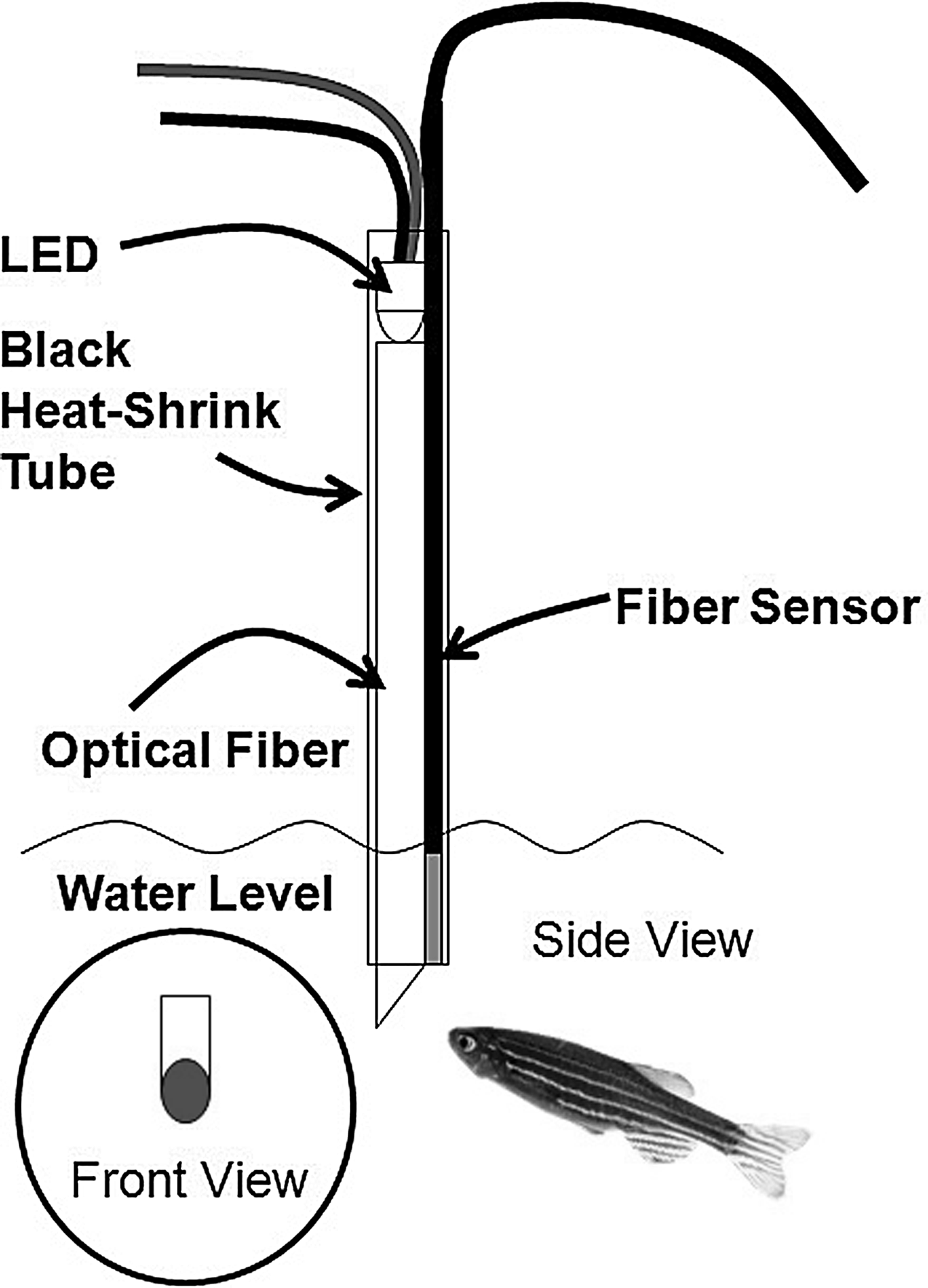
Side view and front view of response key. The tip of the optical fiber under water was illuminated by a LED that was attached to the other end of the fiber. The approach response to the key was detected by a reflective-type fiber sensor that was attached to the optical fiber with a black heat-shrink tube.
Experimental control equipment and software
The timing of the fish responses and all experimental events were recorded by a notebook PC (DELL Latitude D600). Both the output from the fiber amp, the control of servo motor, and LED were accomplished through a universal I/O board (Pololu Mini Maestro 12-channel USB servo controller) connected to the PC via USB interface. The experimental program controlling training and testing events was written in Microsoft Visual Basic Ver. 6.0.
Application of a schedule of reinforcement
Zebrafish were trained under FR10 schedule, and the post-reinforcement pause duration and response pattern were recorded to examine the efficacy of the present system. Our use of 40- or 80-food presentations is 2 to 4 times of the number of food presentations in the other appetitive conditioning experiments that have been tried with zebrafish. 2 In an FR10 schedule, fish were reinforced every tenth response. In other words, fish needed to respond ten times in order to receive one food reinforcement. The primary goal of the this experiment was to demonstrate the suitability of our custom-built feeder for consistently presenting only a few brine shrimp eggs on each trial, so that the zebrafish would run up to 80 trials in one fairly short session without satiating.
Animals
Fish of mixed sex and ages were used. The fish were seven zebrafish, four long-fin, three wild-type purchased from a local pet store, and two wild-type zebrafish obtained from a stock maintained by the support of National Bioresource Project of Japan in RIKEN Brain Science Institute.
Procedure
After a period of adaptation to the experimental tank, each fish was fed in the experimental tank by an automatic feeder. The feeding interval was varied based on Fleshler and Hofman's equation 26 generating a set of variable intervals with a mean value was 20 seconds. The number of food presentations within a daily session was 80. In experiments described below, the fish were occasionally given a small additional amount of flake food (Tetra TetraMin) after an experimental session to ensure that they maintained their weight until the next daily session.
After a few feeder training sessions, the fish were trained to respond to the photo-detector. Trials were spaced by an inter-trial interval (ITI) that was varied based on Fleshler and Hofman's equation 26 with a mean value was 20 seconds. At the start of a trial, the tip of response key was illuminated by a red LED for 8 seconds. If the fish approached the vicinity of the response key while the LED was lit, the LED was immediately extinguished and the fish was reinforced with food from the feeder. On the other hand, if no response occurred within the 8 second interval, the LED was also extinguished and food was presented by the feeder automatically. Whenever food was delivered, the fish was also presented with a secondary reinforcer—a white LED which was attached to the feeder flashed five times as the food was delivered. The red LED remained off for the duration of this reinforcement phase. The duration of the reinforcement phase, including food consumption, was five seconds. Pilot experiments showed that after a number of sessions on this mixed response-dependent and response-independent procedure, a majority of fish learned to approach the response key on 45% of the trials when the RED was lit. Pilot data also showed that fish, reaching this 45% level of responding in Phase 1, were highly likely to succeed in later Training Phases when reinforcement was delivered on a Fixed Ratio Schedule. Thus, we chose 45% as an arbitrary response acquisition criterion.
After response training phase was complete, a Fixed-Ratio (FR 1) reinforcement schedule in which each response was reinforced was implemented. If during a session, fish responded without any decrement in response rate compared to the previous session, the number of response required to be reinforced (FR value) was increased on the next session. The FR value was increased gradually from one to ten across sessions. When the FR schedule was in effect, the red LED was illuminated continuously except during the reinforcement period. For seven fish, a session terminated after 40-reinforcements or 60 min. elapsed which ever occurred first. For two other fish, a session terminated after 80 reinforcements or 60 min. Fish were trained in one daily session. The number of training sessions required for the fish to reach an FR 10 schedule was between 50–150.
Statistical analysis
To analyze the fish's response pattern, a two-segmented linear estimation method 27 was applied to the averaged response pattern. The estimation was performed by SigmaPlot 12.0 (Systat Software Inc). The range of adjusted coefficient of determination (R2adj) for each averaged response pattern was from 0.996 to 0.999.
Results
Feeder design, construction, and the precision
After many adjustments in the development of the feeder, we finally settled on a feeder that was activated by a servo motor (Futaba S3114) that moved a 400-μm-diameter piano wire within a straight brass tube. The inner diameter of the tube was 600 μm. There was a 400 μm by 1000 μm square cavity on the top of the tube that extended at 3 mm from the end. When the feeder was not activated, the wire protruded from the end of the tube by 1 mm, which meant that the cavity was filled by the wire. When the feeder was activated, the wire was retracted by a servo motor that dropped several decapsulated brine shrimp eggs into the cavity from the food container. When the wire returned to its resting place, a small amount of decapsulated brine shrimp eggs were ejected from the spout by the piano wire (Fig. 2A). The food container was a 10 mm thick acryl panel drilled inside. Silica gels were set in a compartment that was vented to the food container so as to keep the brine shrimp eggs dry and less likely to stick to the apparatus. The main frame was a 10 mm thick acryl panel that had a recess on the top. The recess was drilled as a funnel so as to reach to the cavity of the brass tube. The brass tube was inserted into a 1 mm diameter hole drilled from the rear side to a 3 mm diameter drain hole drilled from the bottom. The brass tube was bonded to the hole by epoxy bonding agent. A white LED was attached parallel to the spout. The two panels were bonded to each other so as to form a food container. In the last step, a micro servo motor was attached to the acryl panel by hot-bond, and a 400 μm diameter piano wire was inserted into the brass tube. One end of the piano wire was attached to arm of the servo motor (Fig. 2B).

Feeder mechanism
In a performance test of the feeder, the feeder was set on a white paper and all eggs dropped during each feeder activation were counted for 100 feeder activations. The mean number of eggs dropped at a time was 13.7 (SD=3.8). The median, mode, and interquartile range were 14, 14, and 5, respectively. The total weight of the eggs delivered was about 8 mg for one hundred presentations. Thus, the mean weight of eggs presented in a single reinforcement was about 80 μg.
Figure 3 shows the average response pattern of the last ten sessions for seven subjects trained in a 40-reinforcement condition. The x-axis shows the average time from the last reinforcement. The y-axis shows cumulative response from the last reinforcement. Horizontal bars indicate the standard deviation (SD) of average time to complete the nth response from the last reinforcement. Except for subject L3, there is a break point or elbow in these functions at about 20 sec. The range of the break points calculated by two segmented linear estimation method was 13S to 36.5S. The range of average inter-reinforcement interval was from 38.8S to 74.3S. The values were in a range from 1/4 to 1/2 of the average inter-reinforcement interval. Earlier work on goldfish also show a similar pattern in FR schedule. 29 In other species, such as pigeons and rodents, the ‘break point’ or post-reinforcement pause was typically from 1/4 to 1/2 of the inter-reinforcement interval in FR and fixed interval schedule.30–35

Averaged cumulative record. Left side panels show mean results of each long-fin type subject, and the right side panels each wild-type subject. L and W in the panels indicate long-fin and wild-types, respectively. The error bars represent standard deviations. The x-axis indicates elapsed time since the last reinforcement. Lines in each panel are predicted by two segmented linear estimation method. BP in each panel indicates break point calculated by two segmented linear estimation method. R2 adj is the adjusted coefficient of determination.
Figure 4 shows cumulative records of two 80-reinforcement subjects: MZ2010RW-3 and MZ2010RW-36. In a cumulative record, the total responses are plotted as a function of time. A faster rate of responding is indicated by a steeper slope and a horizontal line indicates a pause in responding. In many species, a FR schedule shows a “break and run” response pattern in which subjects pause for a short period of time following reinforcement (indicated as a slash line in the record, see Ref. 28). Both subjects showed very clear break and run patterns similar to that found for goldfish.29,36 There was no evidence of satiation in that the fish did not stop responding for long periods of time within a session, even though a total of 800 responses occurred involving a total of 80 reinforcements.
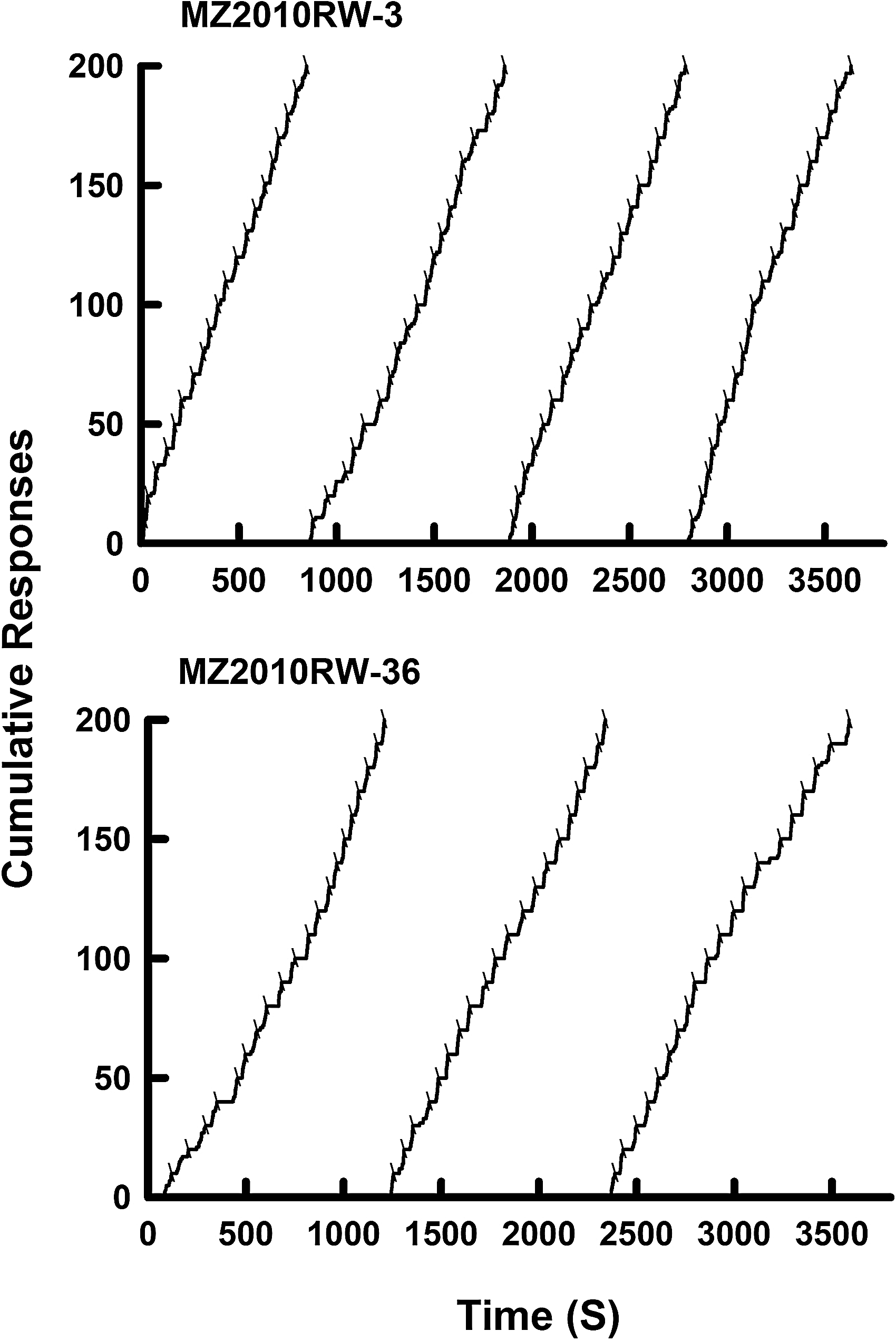
Cumulative records of 80-reinforcement subjects: MZ2010RW-3 and MZ2010RW-36 in the last session. The top panel shows a result of subject MZ2010RW-3. The bottom panel shows a result of subject MZ2010RW-36. Tips on the cumulative lines indicate reinforcements. RW in each panel indicates Riken-Wild Type. In order to show all response patterns in the last session, each line was reset to the zero-point every 200 responses. The second line shows response pattern between 201st to 400th responses, and so on.
Discussion
The present report is the first to show fully automated appetitive conditioning for individual zebrafish. The chief difficulty to overcome in designing an appetitive operant conditioning procedure for zebrafish was to deliver minute quantities of food so that the fish would not satiate after only a few reinforcements as with standard food delivery systems. 2 It is important to note that, with the present system, the two subjects reliably responded even when the number of reinforcement was increased up to 80 a session with no satiation. Thus, the present feeder can be used for behavioral experiments that require delivering a large number of reinforcements within a single session. This makes it be possible to train fish in an experimental situation in which all of the animal's daily food requirement is delivered contingent on the animal's behavior in the test paradigm. This will even further increase training efficiency and minimize investigator time. Since the apparatus is fairly small and simple, it should also allow the training of many fish simultaneously to increase yield in behavioral experiments. The precision of food delivery in the present system may also allow more ethological investigations of zebrafish such as the circadian rhythms of feeding behavior of zebrafish. The present experimental paradigm may also be used to explore temporal aspects of zebrafish behavior.
The response pattern generated by zebrafish in FR schedule shows that zebrafish behavior in this task is governed by the same general principles as other vertebrates. The present results reveal that many complex behavioral experiments involving choice, timing, sensory thresholds, and learning and memory can be conducted with zebrafish with a degree of efficiency and precision typically found with more popular vertebrate behavioral models such as rodents, birds, and primates. For reasons mentioned earlier, the zebrafish is becoming the premier vertebrate model for investigations of the molecular and genetic basis of vertebrate development and adult behavior. We believe the present development of automated experimental system will greatly facilitate progress in behavioral studies for zebrafish.
Footnotes
Disclosure Statement
No competing financial interests exist.