
Abstract
Post-mortem computed tomography (PMCT) has become a standard procedure in many forensic institutes worldwide. However, the standard scan protocols offered by vendors are optimised for clinical radiology and its main considerations regarding computed tomography (CT), namely, radiation exposure and motion artefacts. Thus, these protocols aim at low-dose imaging and fast imaging techniques. However, these considerations are negligible in post-mortem imaging, which allows for significantly increased image quality. Therefore, the parameters have to be adjusted to achieve the best image quality. Several parameters affect the image quality differently and have to be weighed against each other to achieve the best image quality for different diagnostic interests. There are two main groups of parameters that are adjustable by the user: acquisition parameters and reconstruction parameters. Acquisition parameters have to be selected prior to scanning and affect the raw data composition. In contrast, reconstruction parameters affect the calculation of the slice stacks from the raw data. This article describes the CT principles from acquiring image data to post-processing and provides an overview of the significant parameters for increasing the image quality in PMCT. Based on the CT principles, the effects of these parameters on the contrast, noise, resolution and frequently occurring artefacts are described. This article provides a guide for the performance of PMCT in morgues, clinical facilities or private practices.
Introduction
The use of computed tomography (CT) has been well-established in clinical radiology for a long time, and CT scanners have experienced various stages of development. Nowadays, most scanners use the x-ray fan-beam technique combined with detector arrays opposite the x-ray tube, perform helical (spiral) scanning and utilise reconstructions based on filtered back-projection (FBP) or iterative image reconstructions, which are considered third-generation multi-slice CT (MSCT) scanners.1,2 MSCT, multi-row CT or multi-detector CT (MDCT) scanners are based on the use of several rows of multiple small detectors, and the scanners are specified by the maximum number of slices that can be acquired simultaneously (e.g. 4-, 8-, 16-, 32-, 64- and 128-slice MSCT). 3 Acquiring slices simultaneously results in a reduced acquisition time and reduced heating of the x-ray tube. Applying a widened x-ray beam along the z-axis was introduced in 1992 (CT-Twin), but the birth of the MSCT can be dated to 1998. 3 In 2002, the first 16-slice CT scanners were installed, followed by 32- and 40-slice scanners in 2003 and 2004, respectively, and 64-slice scanners in 2005. 3 At the same time, post-mortem CT (PMCT) and PMCT angiography (PMCTA), as a supplement to autopsy using the term ‘Virtopsy’ or ‘virtual autopsy’, arose throughout the world.4–8 As forensic radiology, and especially PMCT, continues to grow, forensic institutes that have recently started performing PMCT depend on the vendor’s program settings or the knowledge of clinical users. However, the needs of clinical and forensic radiology differ greatly, and two major advantages in PMCT that lead to an improvement in the image quality are the ability to neglect radiation exposure and the absence of motion artefacts. 9 Therefore, the PMCT and PMCTA parameters have to be adjusted to use these advantages to achieve the best image quality. Apart from the technology used, the image quality itself is dependent on user-selected pre-scan acquisition parameters and user-selected post-scan reconstruction parameters. Below, we explain the CT principles, and based on these, we recommend relevant parameter adjustments for PMCT. The aims of this review are to give an overview of parameter adjustments to enhance the image quality in PMCT and to offer information on current CT technologies.
Contrast, noise and spatial resolution
First, the term ‘image quality’ must be defined. It can be divided into objective and subjective quality. Subjective image quality mainly depends on the perception, individual preferences and former experiences of the observer, while the objective quality criteria can be measured objectively. The main characteristics of objective image quality are the contrast, noise and spatial resolution. The contrast can be described as the depiction of different adjacent densities and depends on the administered x-ray photon energy and the type of tissue or material that has been penetrated. 10 The number of detector-captured photons is limited, and the detector measurements are randomly fluctuating, which causes quantum mottle (noise), displayed as graininess in the reconstructed images.1,11 The spatial resolution describes the ability to distinguish between the smallest, most closely spaced elements in an image and is mainly limited by the aperture and detector size. 11 The noise and the spatial resolution are image characteristics that are interlinked. So, trade-offs have to be made according to the anatomical region of interest. Apart from the technology used, the image quality itself is dependent on the acquisition parameter settings and the reconstruction parameter settings.
Artefacts
Further, objective image quality is affected by the presence of artefacts. In CT imaging, a variety of artefacts with different causes may occur. In the following, only the most common artefacts are mentioned, which can be significantly reduced by parameter adjustments.
Beam hardening (BH) may occur as cupping artefacts. Cupping artefacts refers to the x-ray photons penetrating the centre of an object being hardened due to the higher radio-opacity in the centre than at the edges of an object. 12 BH may appear as hypodense dark streaks along the x-ray path through thick regions of bone or contrast media.11,13 The Hounsfield bar is a known example and is described as the appearance of a dark streak between the petrous bones in the base of the skull. 13 Partial-volume artefacts (PV) may occur if detector elements are partly shaded by the edge of a high-contrast structure. 13 Thus, the attenuation measured by the detector element is a blend of the high-contrast structure and the surrounding low-contrast structure, which is displayed as an incorrect HU value. PV artefacts occur in-plane and along the z-axis. 13 Windmill (spiral) artefacts (WM) are caused during helical data acquisition by high edge differences between two detector rows due to the layout of the anatomical structures.11,14,15 These artefacts appear as streak-like patterns that seem to rotate when scrolling through the images. 16 Metallic artefacts due to implants or foreign bodies are caused by a mixture of the above-mentioned artefacts but are mainly due to heavy BH. Objects or body parts beyond the in-plane scan field may cause out-of-scan-field artefacts 17 that appear as streaks or shading in the image. 12 Apart from those caused by obese bodies, out-of-scan field artefacts may occur especially by decomposed, charred or frozen bodies due to inadequate positioning.
Generally, the adjustments of the PMCT parameters allow for the reduction of the extent of all these artefacts in post-mortem imaging. But first of all, adequate body positioning is essential.
Body positioning
It is advised to put the deceased into a body bag or on a plastic foil to prevent any soiling of the CT table or damage due to the leakage of any type of body fluid. Depending on the condition of the deceased, a plastic foil beneath the body is preferable, as a body bag may have handles and zippers, which should be removed from the scan region as they may cause artefacts in the images. Another significant reason is that the body bag may be visible in post-processing reconstructions (e.g. volume renderings) or even limit the post-processing possibilities regarding body surface, as it covers the body. Usually, the corpse is in a supine position, depending on its condition. Generally, the arms should be pressed slightly against the body by using position aids and restraining straps to avoid out-of-scan-field artefacts and to be able to use an adjusted small reconstruction field later on. For the purpose of including as much of the body as possible in the scan range along the z-axis, the corpse may have to be pulled cranially on the CT table. To ease the process of pulling the body, silicone or glide sprays can be used to impregnate the table’s mattress overlay in order to keep the table slippery. From a radiological point of view, the head should be carefully aligned along the body axis with a median position of the nose for a better radiological assessment of the head and neck region. Furthermore, as the number of captured x-ray photons is affected by the size of the penetrated object, the BH artefacts and image noise can be reduced for thoracic and abdominal scans by moving the arms above the head.14,18 However, the risk of post-mortem alteration and the potentiality of causing post-mortem findings due to body repositioning have to be considered. Therefore, a previous PMCT scan for documentation purposes, without the anatomically adjusted repositioning of the head or the elevation of the arms, is advisable. Thus, it is recommended to perform a whole-body scan as a basic scan without repositioning the head or elevating the arms in order to detect post-mortem findings due to body repositioning during the PMCT examination. However, a correct symmetric position is always dependent on the extent of rigor mortis and on the condition of the corpse, for instance it may not be possible to place charred bodies in a specific scan position.
The body has to be positioned in the centre of the gantry to obtain the best image quality (Figure 1). Additionally, recent dose-modulation algorithms generally calculate the dose in the centre of the gantry, so careful patient centring is required. First, the body has to be placed in the middle of the table width. Second, the height of the table has to be selected so that the decedent is located in the middle of the gantry to achieve the best image quality. This approach may be difficult for obese or decomposed, bloated bodies, as the skeleton may be in a low position and thus at a greater distance from the iso-centre of the CT gantry due to the extended size of the abdominal girth. The gantry diameter is larger than the scan field-of-view, and this should be taken into account by performing an additional scan with the bloated abdomen beyond the standard scan field but with the skeleton positioned closer to the iso-centre of the CT gantry.

Correct body position in the centre of the gantry is required for the best image quality. In the left column, a spine phantom is positioned almost in the iso-centre of the gantry (a1). In contrast, the right column displays a spine phantom at the edge of the standard scan field (b1). The reconstructions of the spine phantom in the centre of the gantry (a2) exhibit better image quality and significantly less noise compared to the reconstructions of the spine phantom at the edge of the standard scan field (b2). The image quality decreases with the distance to the iso-centre.
After adequate body preparation and positioning, acquisition parameters (prior to the PMCT scan) and reconstruction parameters (after the PMCT scan) have to be adapted in order to achieve the best quality. Table 1 (acquisition parameters) and Table 2 (reconstruction parameters) display a summary of recommended parameter adjustments for PMCT and their main effects regarding contrast, noise and resolution as well as artefacts.
A summary of recommended acquisition parameters for PMCT examinations.
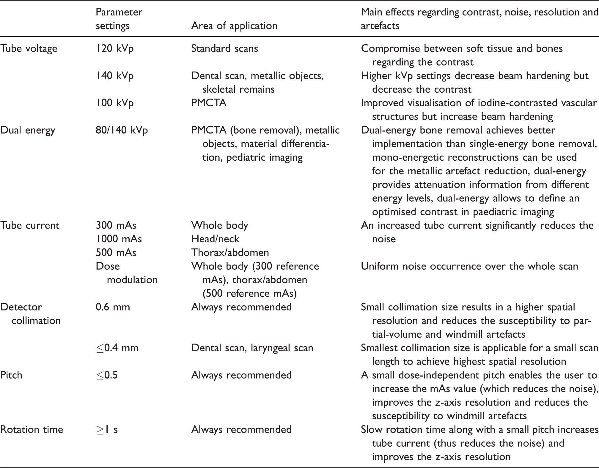
The indicated values are guide values, as depending on the CT scanner, the technical capabilities vary.
PCMT: post-mortem computed tomography; PMCTA: PMCT angiography; CT: computed tomography.
A summary of recommended reconstruction parameters for PMCT examinations.
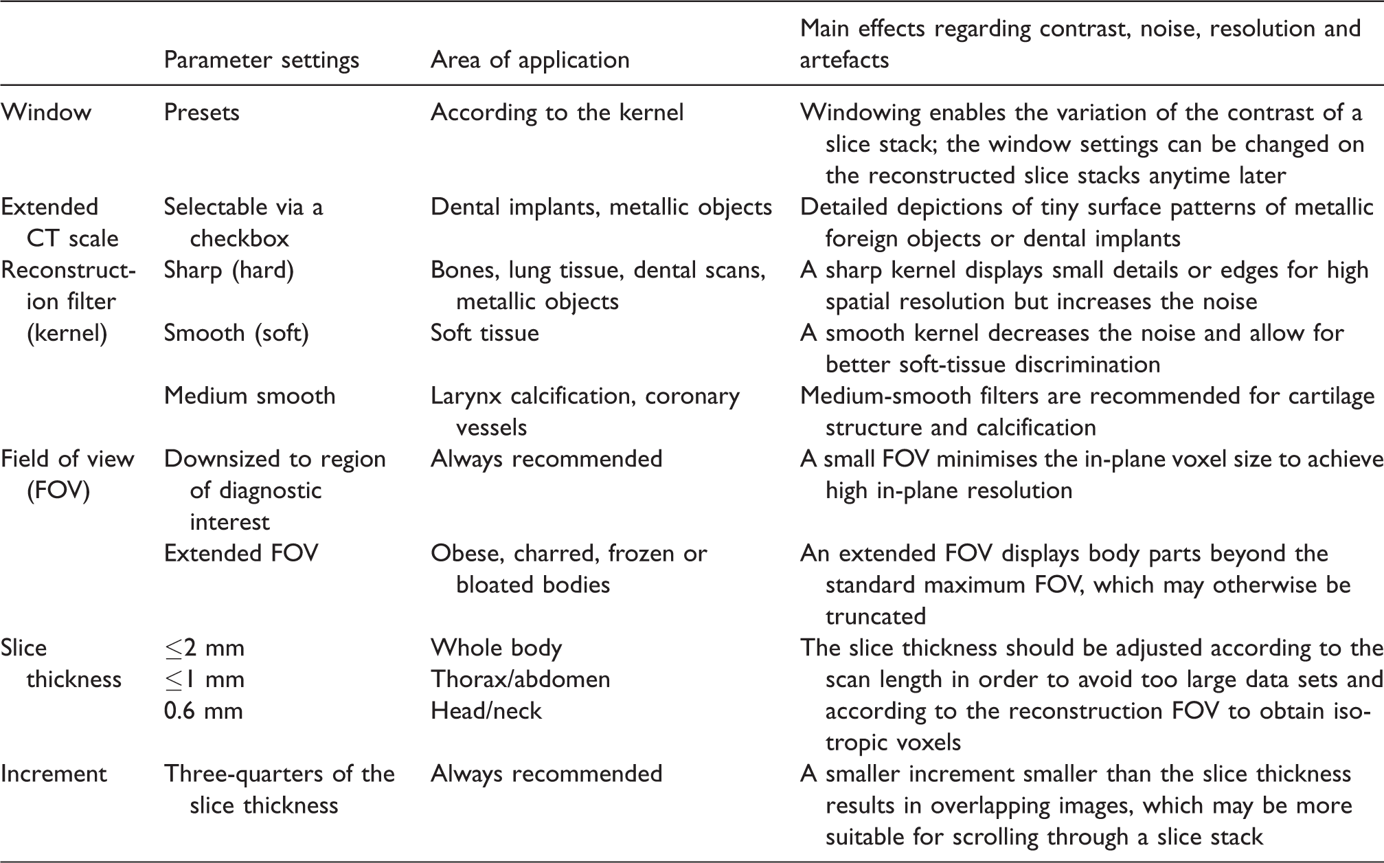
The indicated values are guide values, as depending on the CT scanner, the technical capabilities vary.
Acquisition parameters
The acquisition parameter settings have various influences on contrast, noise and spatial resolution. Most of these parameters affect the radiation dose. PMCT is not limited by radiation dose considerations towards the examined person. Therefore, the acquisition parameters can be optimally adjusted to achieve a high image quality.
Tube voltage
The contrast is mainly affected by the x-ray photon energy, which can be adjusted by the x-ray tube voltage settings. 10 An increased tube voltage reduces the contrast, and thus the tube voltage settings should be adjusted according to the radiological interests, which have to be assessed. 19 The user has to select a tube voltage level based on the kilovolt peak.19,20 Usually, 120 kVp is used in clinical CT, as it provides the best compromise between imaging the soft tissue and bones, 18 which is also applicable for standard PMCT. Higher kilovolt peak settings reduce BH, with the disadvantage of a lower contrast. 14 Therefore, in PMCT, additional scans with higher kilovolt peak settings (e.g. 140 kVp) should be considered for dental scans or scans with a prosthesis, spondylodesis or osteosynthesis to reduce the metallic artefacts due to dental or metallic implants. Further, high-energy PMCT may also be considered for exhumed bodies or any skeletal remains for best osseous depiction, neglecting soft-tissue contrast. Low kilovolt peak settings (e.g. 100 kVp) in turn improve the visualisation of iodine-contrasted vascular structures in angiographic examinations, as the attenuation of the iodine-containing contrast media will be increased,21,22 although lower kilovolt peak settings generally increase the susceptibility for BH.19,22 If available, dual-energy technology offers special advantages for metallic artefact reduction23,24 or CT angiography, for example regarding bone removal.25,26 Using dual-energy CT (DECT), the different contrast behaviours of iodine according to the energy spectrum can be used to highlight the contrast media optimally and differentiate it from the bones or soft tissue. 27 Regarding post-processing, dual-energy bone removal achieves better implementation than single-energy bone removal. 27
DECT
DECT uses two different polychromatic x-ray spectrums for acquiring measurements of the same slice stack. Several vendors offer different DECT technologies, such as utilising two scanner-integrated x-ray sources (dual-source DECT), performing twin-beam single-source CT using gold (low-energy) and tin (high-energy) pre-filters, applying rapid kilovolt peak switching associated with a gemstone scintillator detector and using a dual-layer detector or alternating kilovolt peak settings with each rotation (dual-scan single source).28–30 The DECT data of two different energy spectra allow for extrapolating mono-energetic reconstructions at different selectable kiloelectron volt levels. 31 The term ‘kiloelectron volt’ is usually used in DECT, as it describes the mean energy of the x-ray spectrum. 28 Those mono-energetic reconstructions can be used for the metallic artefact reduction of dental restorations 24 or any orthopaedic implants, 32 which is significant for radiological identification. DECT may also be considered in post-mortem paediatric imaging to define an optimised contrast by selecting the desired kiloelectron volt value using mono-energetic reconstruction. Further, DECT provides attenuation information from different energy levels, which shows potential in forensic imaging, for example to differentiate foreign bodies, 33 to discriminate drugs in body packs 34 and to discriminate ferromagnetic from non-ferromagnetic projectiles for magnetic resonance imaging. 35
Tube current
The use of an increased radiation dose to obtain a high image quality in PMCT is frequently mentioned in the literature,18,36,37 although it is intended to increase the tube current (tube amperage). The tube current is essential for the intensity of the noise (Figure 2). Thus, an increased tube current significantly reduces the noise.14,38 The tube current level is limited by the scan length. Thus, in addition to a whole-body scan, separate head/neck and thorax/abdomen scans with higher milliampere-seconds settings are recommended in the literature. 18 The tube current is vendor-dependent, indicated together with the slice scan time as the tube current-time product using milliampere-seconds. 11 The radiation dose is directly proportional to the administered tube current-time product based on the milliampere-seconds value.10,11,20 Image acquisition using increased milliampere-seconds settings is the foremost advantage in PMCT compared to clinical CT.

The difference between 250 mAs and 1500 mAs with respect to the presence of noise is impressively illustrated by a head scan. The different stages of the milliampere-seconds settings show the reduction of the image noise from 250 mAs to 1500 mAs. When increasing the tube current, the effect of the noise reduction will approach a limit. As shown, the difference in image quality is less pronounced between values >1000 mAs.
Dose modulation
The initial purpose of automatic exposure control or dose-modulation techniques is decreasing the radiation dose by the modulation of the tube current for the regional body anatomy,39–41 which at first glance may be considered unnecessary in PMCT. However, the noise will be adjusted as the tube current is adjusted using dose-modulation techniques,39,40 which results in more uniform noise occurrence over the whole scan. Several vendors provide automatic exposure control with different technical approaches. A uniform noise distribution is also beneficial for PMCT. By selecting a high initial reference milliampere-seconds value, the overall administered radiation dose can be increased to improve the image quality combined with dose-modulation, resulting in more uniform noise. However, the use of dose modulation for a combined scan of the head and neck regions may result in unwanted dose distribution, as significantly less exposure to the head region compared to that to the lower neck will occur due to the shoulders. Thus, dose modulation for the head and neck region may not result in the desired image quality for the head region. Furthermore, it must be of concern that paediatric cases as well as heavily decomposed, mummified or charred bodies may initially be low dosed due to the automatic dose modulation, so the reference milliampere-seconds value has to be kept in sight and adjusted if necessary.
Detector collimation
The user-selected detector collimation affects the spatial resolution 42 and defines the reachable, minimal slice thickness (SL). 3 A small collimation size is always recommended in any PMCT examination, as it results in a higher spatial resolution 11 and reduces the susceptibility to PV 13 and WM3,15 artefacts, with the drawback of increased noise. 43 If necessary, after the PMCT scan, thicker slices can be reconstructed from the same raw data, or the SL of thin-sliced reconstructions can be increased using dedicated post-processing software. 44
Pitch and rotation time
Helical scanning means that the table moves through the gantry during x-ray rotation with the constant acquisition of data, 3 which is described by the pitch. However, two different definitions of the pitch factor are used by vendors 38 : detector pitch3,43 and volume pitch. 43 Detector pitch is defined as the table feed per rotation of the x-ray tube divided by the total detector collimation and therefore is the total number of all simultaneously active detector rows.3,44 In contrast, volume pitch excludes the number of active detector rows, and thus it is defined as the table feed per rotation of the x-ray tube divided by the detector collimation of a single row. 45 The pitch factor along with the rotation time affects the image quality in different ways. In general, a larger pitch may cause gaps between x-ray beam trajectories and thus gaps in the data acquisition,1,15,43 which results in a lower image resolution. In contrast, a small pitch enables more x-ray photons to contribute to the calculation of an image due to the overlapping beam trajectories.1,2,15,43 Thus, a small pitch automatically affects the tube current, and a (vendor-dependent) dose-independent pitch enables the user to increase the milliampere-seconds value, as a higher maximum dose is applicable. Additionally, a reduced rotation time allows for increasing the tube current. Further, a small pitch improves the z-axis resolution, as fewer anatomical changes are located within the range of interpolation.2,46 Major changes of the anatomical structures within the interpolation range may cause WM artefacts.3,15,16 So, apart from the narrowed collimation, the likelihood of these WM artefacts is also decreased by using a small pitch.3,15
Reconstruction parameters
After the data acquisition, a raw data set is computed that is the basis for further image reconstructions. These raw data sets are used for the reconstruction of slice stacks in accordance with the radiological interests for the subsequent evaluation and interpretation of the examination. From the same raw data set, several slice stacks with different reconstruction parameters can be computed. 15 However, raw data sets are not stored due to their size, and so they must remain on the CT workstation until the reconstructed slice stacks have been reviewed in the event that further special reconstructions are desired.
Window settings
The measured attenuation values are converted into a calculated integer (CT number) indicated in HU. 1 The attenuation coefficient of water is used as a reference for the calculation of each CT number. Thus, the CT number for water is approximately 0, for air approximately –1000 and for dense cortical bone approximately +1000 1 for a commonly used x-ray beam energy value (120 kVp). The CT numbers are displayed as grey levels. 1 The number of grey levels that could be visually discernible is limited.1,2 Thus, the range of grey levels has to be adapted to the amount of CT numbers. Otherwise, for example, soft tissue would not differ visually, as the CT numbers of soft tissue have too little variation and will not be visually distinguishable. Windowing allows for allocating grey levels in the image based on the window width and window centre for diagnostic interests (e.g. bony structures, soft tissue or lung structure). Thus, the range of displayed CT numbers can be subsequently adjusted to achieve the desired image contrast for the radiological interests by windowing. However, the CT number (and the HU value) is fixed independently from the windowing. The window width defines the quantity of CT numbers that should be displayed. 1 This means that the window width sets the range of CT numbers in which all grey levels are covered, and any values outside this range are displayed either in black (lower values) or white (higher values). The window level or window centre defines the central point of the window width along the HU scale 1 and thus the central CT number value over which the window width ranges. 2 Thus, windowing enables the variation of the contrast of a slice stack. Usually, CT scanners offer various specific window presets for image review and reconstruction, 2 but the window settings can be individually and interactively set and changed on the reconstructed slice stacks anytime later.
Extended CT scale
In addition to the discussed reconstruction variations, the extended CT scale (ECTS) technique extends the maximum window range of a reconstructed slice stack tenfold, as the CT numbers will be scaled down by a factor of 10, which in turn expands the CT scale from approximately 4000 HU to approximately 40,000 HU. 47 Thus, this approach does not necessarily reduce the artefacts, but it enables better image contrast for a hyper-dense material by windowing into a higher range. Therefore, a more accurate depiction of materials with high radio-opacity, such as metallic objects, can be achieved. Reconstructions using ECTS enable detailed depictions of tiny surface patterns of metallic foreign objects for a clear identification of the objects. 48 The precise depiction of foreign bodies is a major task of PMCT, for example to distinguish between a common coin and a button battery is of substantial importance.48,49 Furthermore, the ability to use ECTS yields advantages for dental identification, as dental implants are depicted more accurately 50 on PMCT for better comparison to ante-mortem x-rays. Additionally, high-density objects can be discriminated based on the possibility of measuring higher HU values (Figure 3) at different kilovolt peak settings.33,35
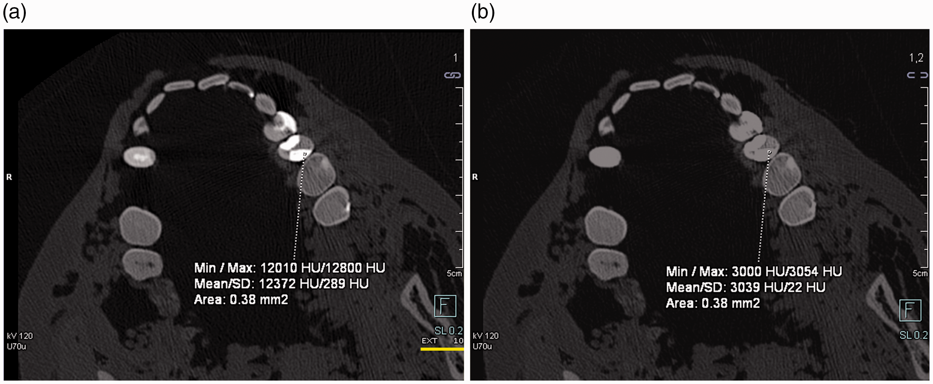
Apart from depicting high-density objects (e.g. dental implants) more accurately, reconstructions using (a) the extended computed tomography scale (ECTS) enable HU measurements over a higher range compared to (b) standard CT reconstructions. ECTS (in combination with multi-scan, multi-energy post-mortem computed tomography) enables the discrimination of high-density objects to a certain degree.
Reconstruction filter
A reconstruction filter (kernel), actually an algorithm, defines a compromise between image noise and spatial resolution by blurring the image, as blurring reduces the image noise. 1 Regarding the radiological interests, soft tissue will usually not need well-defined edges for diagnostics. Thus, reduced image noise is preferred over spatial resolution. Smooth (soft) filters are applied that decrease the noise and allow for better soft tissue discrimination.1,2,11 In contrast, displaying small details or edges of bones requires a high spatial resolution, and the image noise interferes less with these images, and hence sharp (hard) filters are applied.1,2,11 Thus, smooth (soft) filters for soft tissue and sharp (hard) filters for bones and lungs have to be used for separate reconstructions. Of particular note is the use of medium-smooth filters for the laryngeal region 18 in cases of strangulation due to the cartilage structure. Further, medium-smooth filters are recommended to display the calcification of the coronary vessels better. 51 Additionally, special filters have been developed for defined anatomical regions, for example for a separate head scan.
Field of view
Reconstructed sectional slices are three-dimensional (3D), and the picture elements are cuboid-shaped. Thus, a reconstructed slice consists of volume elements, so-called voxels. The size of the voxel depends on the matrix size and the size of the reconstructed field of view (FOV; x- and y-axis), and the slice thickness (z-axis; Figure 4). Thin-sliced image stacks with almost isotropic voxels are essential for further high-resolved 3D reconstructions. Voxels are considered isotropic if their extension is equal in all three spatial axes.3,15 Primarily, the z-axis resolution is limited by the detector collimation and spiral interpolation algorithm (z-filtering). 15 Therefore, the z-axis resolution or the smallest possible slice thickness has to be mainly defined by the setting of the acquisition parameters, whereas the in-plane resolution is mainly defined by the size of the reconstructed FOV. The general term ‘field of view’ relates to the size of the scanning FOV (sFOV) in axial orientation or to the size of the reconstructed FOV (rFOV) in axial orientation. The extension of the sFOV is described by a diameter, as it is circular according to the rotational movement of the x-ray tube, whereas the rFOV is usually square according to the image matrix. Most types of CT scanners allow for adjusting the rFOV after the CT scan, and the size of the sFOV does not affect the in-plane resolution, while the size of the rFOV significantly does. Usually, the maximum rFOV is 500 × 500 mm according to the maximum sFOV (500 mm), with the centre of the gantry as its centre point. Within the range, the rFOV can be downsized and adjusted to any region of interest to minimise the in-plane voxel size and to achieve high in-plane resolution. Special reconstruction algorithms also allow the rFOV to be extended beyond its initial maximum size with the restriction of less accuracy in the outer range. 2 Such an enlarged rFOV is described as an extended FOV (eFOV). A separate reconstruction using eFOV is recommended for obese decedents to display (with lower quality) the upper extremities on the body, which may otherwise be outside the sFOV and hence truncated. 52 Using eFOV is also suitable for charred, frozen or bloated, decomposed bodies, which may not fit into the standard range of the rFOV. 18
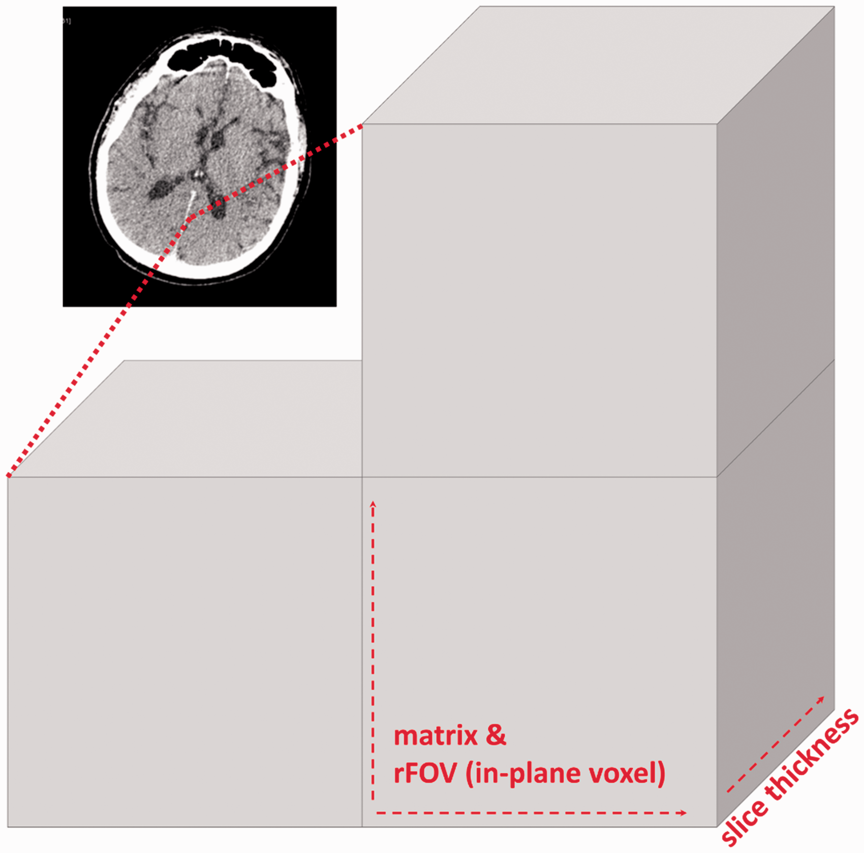
Each CT slice (a) consists of small voxels (b). The size of the voxel is dependent on the matrix, the reconstructed field of view (FOV; in-plane resolution) and the slice thickness (z-axis resolution).
Slice thickness and increment
Current CT technology allows for reconstructing several slice stacks with different slice thickness values from the same raw data set. 21 The slice thickness is usually abbreviated as SL. To reconstruct overlapping images, which may be more suitable for scrolling through a slice stack, the increment should be smaller than the SL (three-quarters of SL). To reduce the noise in the slice stacks along the z-axis, SL can be increased (Figure 5), which may be suitable for soft-tissue diagnostics. However, reconstructions from the raw data set with thick slices are not necessarily required, as the SL of thin-sliced image stacks can also be increased during viewing directly on a dedicated workstation, according to the diagnostic interests. The main advantages of the thin-sliced image stacks are their high spatial resolution, possibilities for almost iso-voxel 3D reconstructions and reduction of partial volume artefacts. 38 An adequate SL for an appropriate scan length is recommended, dependent on the possibilities of the CT scanner or detector collimation. Along with an adjusted rFOV, thin-sliced image stacks consist of small voxels, which provide the basis for further high-resolution 3D reconstructions.21,53 Regarding the radiological identification of decedents, 54 it is recommended to perform additional thin-sliced reconstructions of prostheses or anatomical characteristics with an adjusted small rFOV. For the comparison of ante-mortem data sets and PMCT data sets, the PMCT reconstructions can be matched with ante-mortem data sets using multi-planar reformation for a side-by-side comparison or even image fusion, depending on the applied workstation.54–56

The slice thickness (SL) of thin-sliced reconstructions can be increased by using a dedicated workstation for soft-tissue diagnostics. Thin-sliced (SL: 0.6 mm) reconstructions (a) exhibit increased noise compared to thick-sliced (SL: 3 mm) reconstructions (b), but they provide the basis for further high-resolution three-dimensional reconstructions.
3D post-processing
The reconstructed slice stacks allow for computing volumetric reconstructions. High-quality 3D post-processing requires thin-sliced image stacks reconstructed in an adjusted small rFOV to achieve the highest resolution in all three spatial planes.21,53
Multi-planar reformation/reconstruction (MPR) allows one to compute and display two-dimensional slices with a defined thickness from the whole volumetric data set in any desired plane. 57 Thus, MPRs can be used for reconstructions in any arbitrary plane to display coronal, sagittal or any anatomically aligned oblique plane in high resolution. 43 Currently, MPR allows for the real-time viewing of an already reconstructed slice stack in any arbitrary orientation. However, MPR real-time viewing requires thin-sliced image stacks with almost isotropic voxels for high resolution without step artefacts.2,53 If desired, the slice thickness can be modified during MPR real-time viewing to reduce the noise. A very thick slice of several centimetres (‘ray sum’) may resemble a conventional x-ray image, and this method is frequently used for comparison between ante-mortem x-rays and PMCT reconstructions for identification purposes. 54 Even non-linear or curved reconstructions are feasible2,58 and can be used to reconstruct a panoramic, tomographic image for comparison with an ante-mortem orthopantogram for radiological identification based on dental structures and implants.54,59 Further curved MPR can be used for the purpose of displaying curved anatomical structures in a planar view, for example contrast-enhanced vessels. 60 Generally, MPR reconstructions are advantageous in PMCT, especially if a body could not be positioned correctly in the supine position, for example charred or frozen bodies.
The maximum intensity projection (MIP) depicts the maximum intensity of all data points from the entire volume (Figure 6(a) and (b)). This technique can be described as volumetric visualisation, as the reconstructed MIP can be rotated. Thus, the viewpoint is freely selectable. 58 Usually, MIPs are standard tools in CT-angiography for the better visualisation of enhanced vessels or better differentiation between contrast agents and plaques. 61 Further, this technique can be used to display an overview of the bones, metallic implants or calcifications. 58
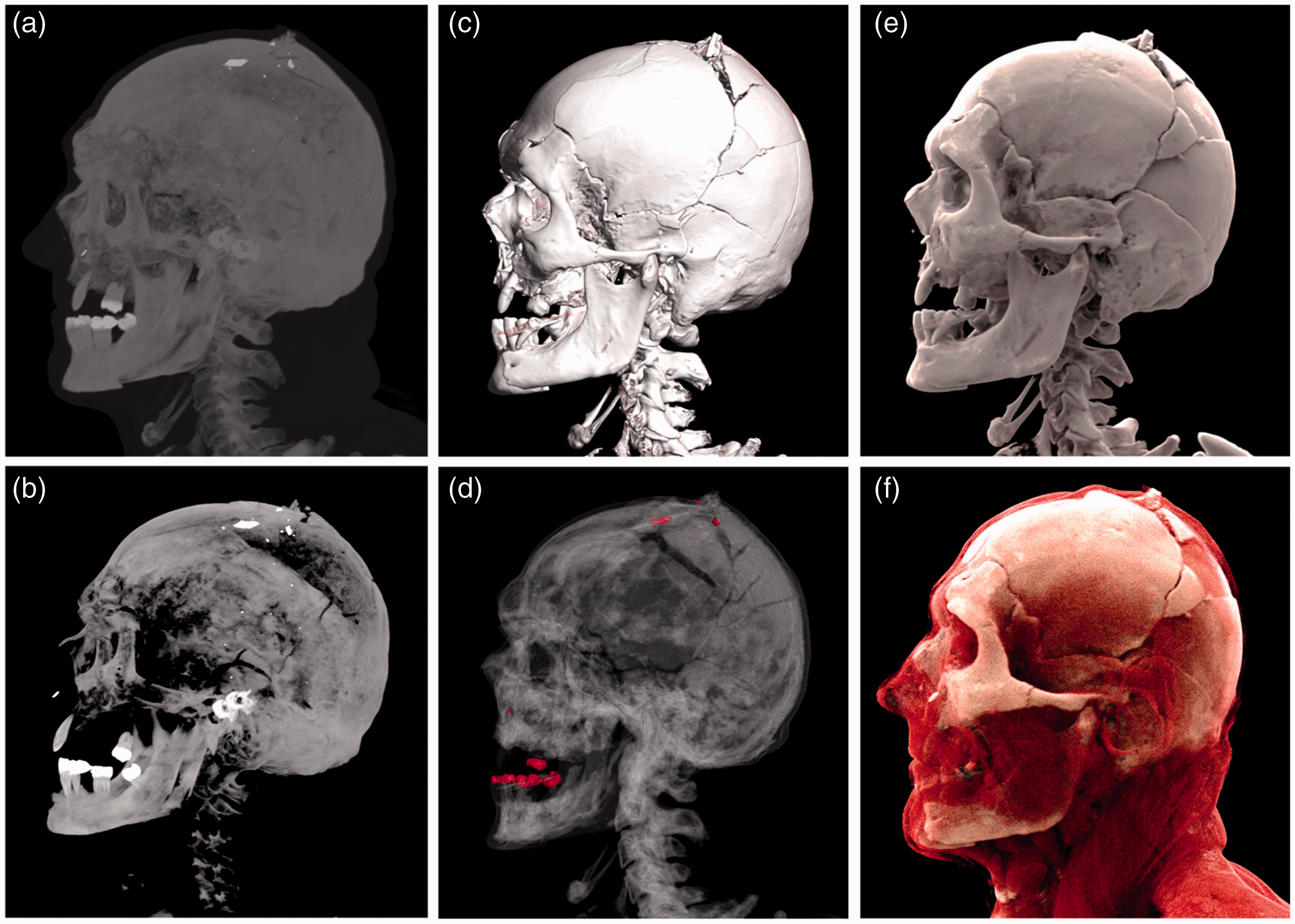
Three-dimensional reconstructions of a headshot displayed as maximum intensity projection ((a) and (b)), volume rendering ((c) and (d)) and cinematic rendering ((e) and (f)) using two different presets for each technique.
Shaded surface display (SSD) can be described as a surface modelling, 57 as it is based on rendering using a mosaic of connected polygons. 58 Therefore, this visualisation technique allows for the surface of an object to be displayed based on HU threshold segmentation, which can be used to identify surface injuries.
However, SSD has mostly been replaced by volume rendering (VR), as SDD could not be established in clinical radiology. 58 VR means that a specific colour and opacity will be assigned to each voxel based on predefined attenuations related to different types of tissue (Figure 6(c) and (d)). Furthermore, a projection technique based on simulated light rays is used, so that each voxel will alternate the colour of the light rays according to its assigned colour and opacity. 62 As different trapezoids are used for tissue separation, the rendered volume can be adjusted based on the radiological interests by changing the gradient of the trapezoid. 62 Vendors offer several presets for different illustrations. This visualisation technique can be used to display the anatomy and pathology in a 3D image, which can be used for real-time viewing. A more recent visualisation technique, comparable to VR, is cinematic rendering (CR). CR may provide further advantages, as this technique computes photorealistic depictions62–64 (Figure 6(e) and (f)). VR and CR play a particular role in post-mortem radiology, as they may provide a more understandable overview of pathologies and injuries for district attorneys and judges. 65 Compared to autopsy, this visualisation technique may provide the in situ depiction of injuries, for example multiple head fractures, 66 which may fall apart during autopsy due to fragmentation, or it may enhance the illustration of the gas distribution across the entire body. For the illustration of the findings, it must be decided whether to use thin-sliced data sets with a smooth (soft) or a sharp (hard) reconstruction filter for the VR or CR reconstructions.
Summary
This article describes the CT principles from acquiring image data to post-processing and recommends parameter adjustments to obtain the best image quality in PMCT. The summary in Tables 1 and 2 provides a quick introduction to PMCT with high image quality and provides a guide for the performance of PMCT in morgues, clinical facilities or private practices.
Footnotes
Acknowledgements
The authors would like to thank Thierry Kaeser for his support regarding technical queries. The authors express their gratitude to Emma Louise Kessler, MD, for her generous donation to the Zurich Institute of Forensic Medicine, University of Zurich, Switzerland.
Declaration of conflicting interests
The authors declared no potential conflicts of interest with respect to the research, authorship and/or publication of this article.
Funding
The authors received no financial support for the research, authorship and/or publication of this article.