
Abstract
In this study, we compared fiber trapping of embeddable and locatable spinning (ELS) with that of sirofil and siro core-spinning with flute pipe air suction. Online pictorial analysis showed that the 3rd ELS was free of the visual fiber loss during the 1st ELS, 2nd ELS, sirofil, and siro core-spinning. This indicated the 3rd ELS possessed high ability of trapping staple fibers. Weight loss of different yarns proved that the 3rd ELS had a statistically higher fiber trapping capacity than 1st ELS, sirofil and siro core-spinning. Yarn visual appearance results showed that filaments failed to be entirely buried in the siro core-spun yarn body due to the staple fiber loss and imperfect filament tension adjustment. Poor trapping and filament fasting of staple fibers might be the reasons for more hairy siro core-spun yarn than other composite yarns. Sirofil and siro core-spun yarn had higher value of coefficient of mass variation per unit yarn length and yarn imperfections than the 3rd ELS yarn which might be probably due to their irregular fiber loss during the sirofil and siro core-spinning. The fiber loss would result in a decrease in yarn cross-section fiber utilization; therefore, sirofil, siro core-spun and the 1st ELS yarn had a statistically lower tensile tenacity than the 3rd ELS composite yarn.
Composite yarn is made of both filaments and staple fibers. 1 The main aim of using composite yarn is to take advantage of different properties of filaments and staple fibers. As some manmade filaments are more even and stronger than natural staple fibers, a combination of these filaments with staple fibers may be conducive to higher qualities for resultant composite yarns. Thus, composite yarns, mostly produced in the ring spinning process, have a higher tenacity and improved irregularity than the equivalent normal ring spun yarns. 2
Conventional methods to obtain ring composite yarns include improved ring spinning technologies such as sirofil and core-spun. Sirofil spinning is developed from siro-spinning to strengthen the spun yarn, in which one of the siro components is replaced by filaments inserted at the back of the front rollers on a ring frame. The sirofil yarn transverse structure presents an ellipse without a hollow shape; the sirofil yarn longitudinal configuration is helical in appearance with the staple stand and filaments torsional on the yarn surface. 3 In contrast, filaments are hidden in the body of core-spun yarn in which the core-filament provides high strength and easy care, while the sheath provides the excellent traditional look, feel, and comfort of natural staple fibers. 4 Thus, periodic core filament exposure due to the poor coverage of staple fibers should be inhibited to cause a barber-pole effect for core spun yarns.5,6 For core-spinning, the best cover is achieved by feeding the filament yarn between double rovings. 7 If spacing of the two rovings is large enough to form a sirospun system, feeding the filament into the sirospun triangle center (denoted as siro core-spun) can also be applied to produce core–sheath yarns.8,9
Apart from resultant yarn appearance, fiber trapping efficiency is another key performance of composite spinning; server loss of valuable fibers such as super fine wool fibers should be avoided. Then, novel composite ring spinning was developed to solve the staple fiber loss problem during composite spinning. One effective method to resolve the problem is spreading multi-filaments into individual filaments before feeding them into the front nip.10,11 Specifically, a slotted roller can be used to spread the multi-filament safely; outspread multi-filament sheet acts as a net to catch staple fibers into the body of a so-called ‘cluster spun yarn’. 12 The three-strand modified method (TSMM) can somewhat improve the fiber loss, and can produce a composite yarn free from the sheath-fiber slippage problem. 13 However, the operation of cluster-spun and TSMM is not convenient enough to be a success in an industrial application. Under this situation, embeddable and locatable composite spinning (ELS) has been proposed recently as a simple way to solve fiber loss and filament-staple fiber slippage problems by well embedding staple fibers into the yarn body. 14 ELS has been achieved its industrial application for super-high-count worsted yarn production in some Chinese (denoted as CN) worsted mills.
Although ELS is simply developed from siro-core and sirofil spinning, it is superior to siro-core and sirofil spinning. Thus, our previous study validates that ELS has a good fiber trapping capacity, and was more suitable to produce high-quality super-fine worsted yarns than siro core-spun and conventional worsted spun methods. However, fiber trapping comparison of three ELS systems with sirofil, siro core-spinning lacks deliberate research. In this study, we focus on an experimental investigation of the fiber trapping performances of the 1st ELS, 2nd ELS, 3rd ELS, sirofil, and siro core-spun during the medium count worsted composite yarn spinning with a suction flute. Online fiber loss photos and resultant yarn weights were carefully studied to compare the fiber trapping capacity of different spinning systems. Properties of produced composite yarns were also examined to reflect the influence of fiber trapping.
Experimental details
In the present work, two worsted roving strands with fineness of 0.28 × 2 g/m and two multi-filaments of polyester with a fineness of 33.3 dtex/24f were used to produce different composite yarns. The physical parameters of the wool fiber and multi-filaments were provided in Table 1. As shown in Figure 1, siro core-spun, sirofil and three ELS methods were used to produce siro core-spun, sirofil and ELS yarns, respectively. All of the composite yarns were produced under the same spinning settings: total draft ratio 30, main draft ratio 22.5, spindle speed 5115 rpm and front roller linear speed 6.31 m/min. An IXUS 75 type Canon digital camera was employed to get the dynamic spinning triangles and resultant yarn appearance for each composite spinning system.
The design of the ring composite spinning methods; (a) siro core-spun method8; (b) 1st generation of ELS; (c) 2nd generation of ELS; (d) 3rd generation of ELS; (e) sirofil spinning method. Physical parameters of the wool fiber and multi-filament

All produced composite yarns were conditioned for more than 24 hours under standard atmospheric conditions (20 ± 2°C and 65 ± 2% relative humidity [RH]) before measuring yarn physical properties including yarn count, tensile strength, elongation, unevenness, hairiness and imperfections. Different composite yarns were weighted per 100 meters on an AUY120 electrical balance after measuring by YG086 Lea's Length Tester; the length of each yarn tested was 300 meters and the results were averaged. The yarn tensile strength was measured using an YG061 single yarn strength tester according to GB/T 3916-1997 single yarn break strength and elongation testing standard. Yarn test speed was 250 mm/min and test gauge was 250 mm. Then the tensile results were averaged after 20 tests for each composite yarn. The yarn irregularity was obtained on YG135E capacitive evenness tester according to the CN GB/T 3292.1-2008 capacitance testing standard; the testing speed was 400 m/min, and the testing time was 2.5 minutes for each composite yarn. The yarn hairiness was measured using a YG172A hairiness tester according to the CN textile industry standard FZ/T 01086-2000. The test speed was 30 m/min and the testing length for each yarn was 100 m. All of the tests were conducted under the standard atmospheric conditions. In addition, Student–Newman–Keuls (SNK) tests and variation analysis were also conducted in the SPSS program to study related testing results; the significance level was 0.05 for the SNK test and variation analysis.
Results and discussion
A pneumatic suction pipe is widely used to suck fiber strands away to prevent fiber wrapping on the rollers when yarns break, which is also beneficial for splicing of yarn. However, some peripheral fibers of spinning strand may become easy to drop down due to negative air pressure generated by the pneumatic suction pipe. Static electrification can also induce fiber loss during the worsted spinning. 15 Thus, we take online pictures of different composite worsted spinning triangles to compare their staple fiber trapping capacity.
Qualitative fiber trapping comparison for different composite spinning
Figure 2 illustrated the situation of fiber trapping during the twisting of components in different composite yarn formation zones. Of course, filaments could trap staple fibers to form a desirable yarn formation zone for each composite spinning system, as shown in Figure 2(a1), (b1), (c1), (d1), and (e1). However, the desirable yarn formation zone failed to last for a very long time during the siro core-spun, sirofil, 1st and 2nd ELS spinning process; this was due to that part of staple fibers at the outermost periphery of yarn formation zone being suctioned away by the flute suction pipe which could be seen in Figure 2(a2), (b2), (c2), (e2), (a3), (b3) and (c3). This might indicate that the filaments were not good enough to trap all staple fibers all of the time in siro core-spun, sirofil, 1st and 2nd ELS yarn formation zones. An excellent fiber-trapping spinning system should have a capacity of re-trapping a staple fiber flow which was formed by dynamic lost fibers. Unfortunately, the fiber flow was hard to be re-spun into yarn body for siro core-spun, sirofil, 1st and 2nd ELS system; even worse, the escaped fiber flow carried other adjacent staple fibers off the staple strand to worsen the fiber loss via the flute pipe suction for the sirofil system which was shown in Figure 2(e2) and (e3).
Staple fiber trapping in different composite yarn formation zones. (a) siro core-spun yarn formation zone; (b) 1st ELS composite yarn formation zone; (c) 2nd ELS composite yarn formation zone; (d) 3rd ELS composite yarn formation zone; (e) sirofil composite yarn formation zone.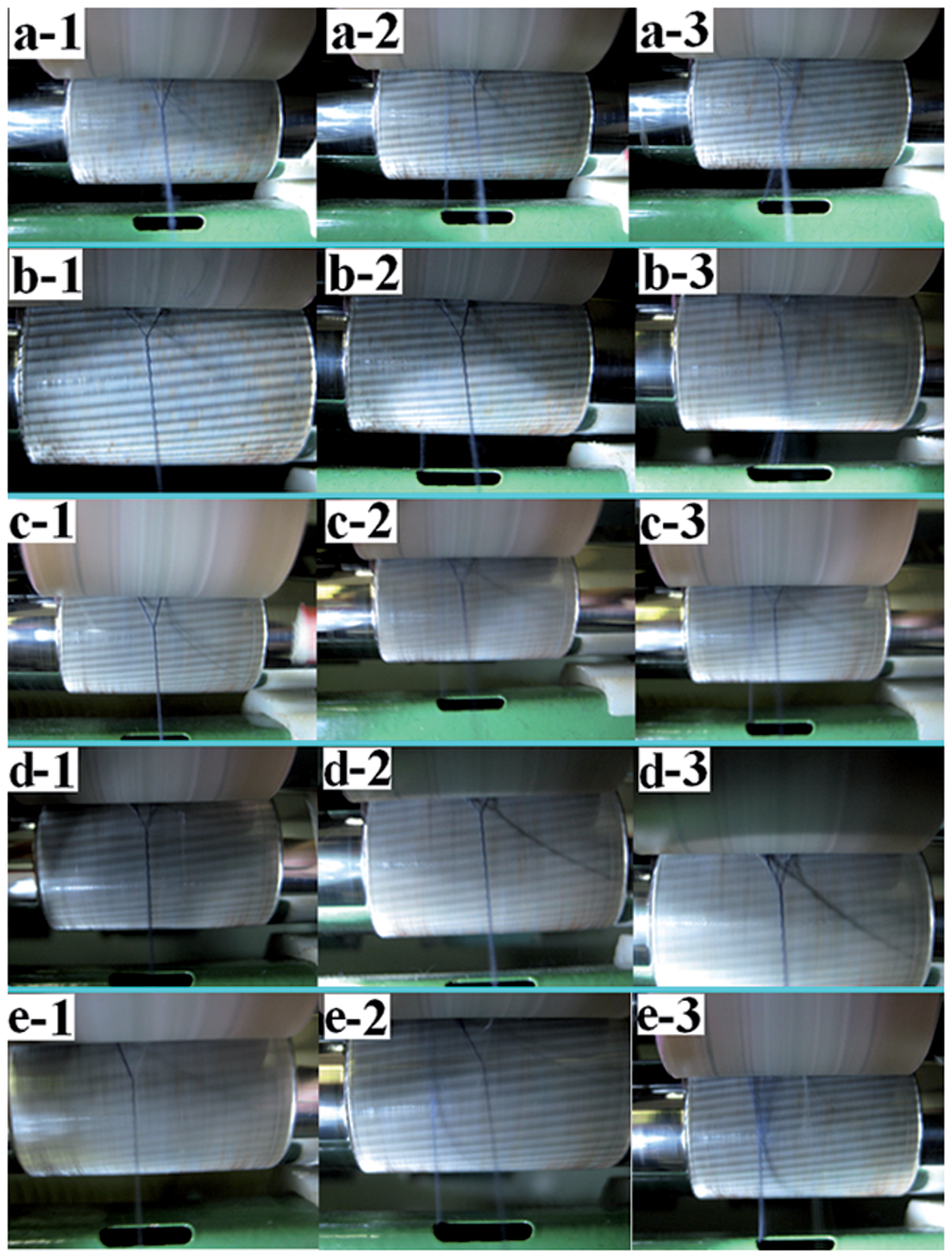
Surprisingly, no lost fiber flow occurred during the whole spinning of the 3rd ELS yarns, which was depicted in Figure 2(d1), (d2), and (d3). The main reason was that the 3rd ELS system could greatly increase the fiber utilization ratio and decrease the fiber fly and loss at the same time during spinning.
14
Second, the 3rd ELS system had a capacity of self-re-connecting a broken staple strand end with filaments, which is illustrated in Figure 3. Even if part of spinning strand end broke, subsequently the output fiber flow from the roller nip would be contacted with the continuous filaments by itself. Thus, the 3rd ELS system was free from the situation that losing fiber flow was hard to be spun into composite yarn body automatically in the other four composite spinning systems.
Automatic staple strand splicing capacity comparison in different systems. (a) siro core-spun; (b) 1st ELS; (c) 2nd ELS; (d) 3rd ELS; (e) sirofil.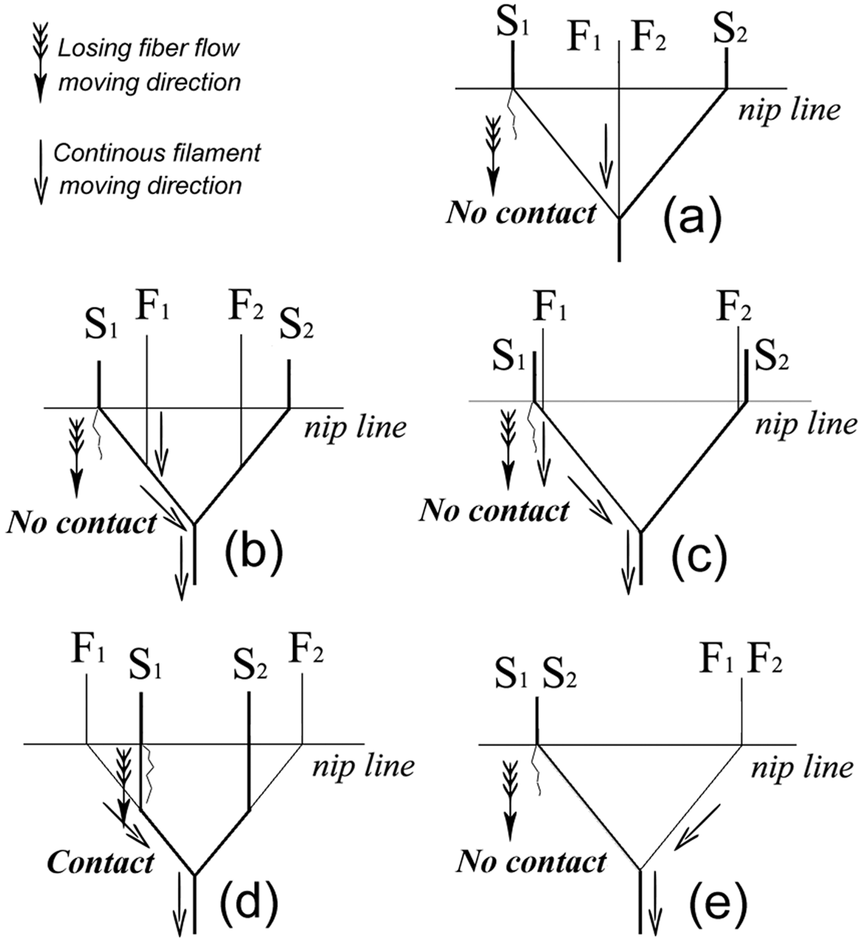
Quantitative fiber trapping comparison for different composite spinning
Comparisons of different composite yarns’ counts
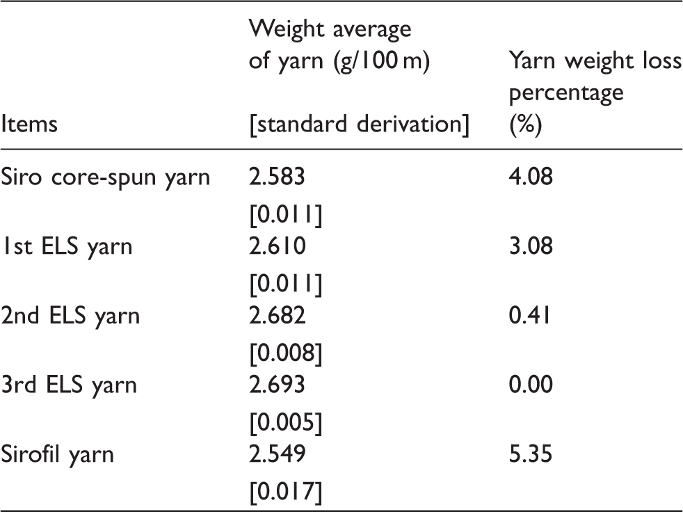
Yarn weight loss percentages listed in Table 2 indicated that the siro core-spun, sirofil and 1st ELS systems were poor in trapping staple fibers into resultant yarn body. In particular, sirofil composite yarn showed the highest yarn weight loss ratio among the five composite yarns. This indicates that the most severe fiber loss occurs in the sirofil system which corresponds well to the pictorial analysis in Figure 2.
Effect of fiber trapping capacity on yarn visual appearance
Different composite yarn appearances are provided in Figure 4. Figure 4(a) shows that filaments were not fully buried in the siro core-spun yarn stem. The key factor might be that filaments’ pre-tension had not been elaborately adjusted according to the true-core yarn producing method.
18
Moreover, the random fiber loss could cause the siro core-spinning triangle to be asymmetrical and imbalanced dynamically, which further interfered with the multi-filament lying at the yarn core throughout. Abnormally long thin sections of yarn stem (Figure 4(a), (b), and (e)) might also be caused by the severe loss of staple fibers during spinning.
Visual appearance comparison of different composite yarns. (a) siro core-spun yarn; (b) 1st ELS yarn; (c) 2nd ELS yarn; (d) 3rd ELS yarn; (e) sirofil yarn.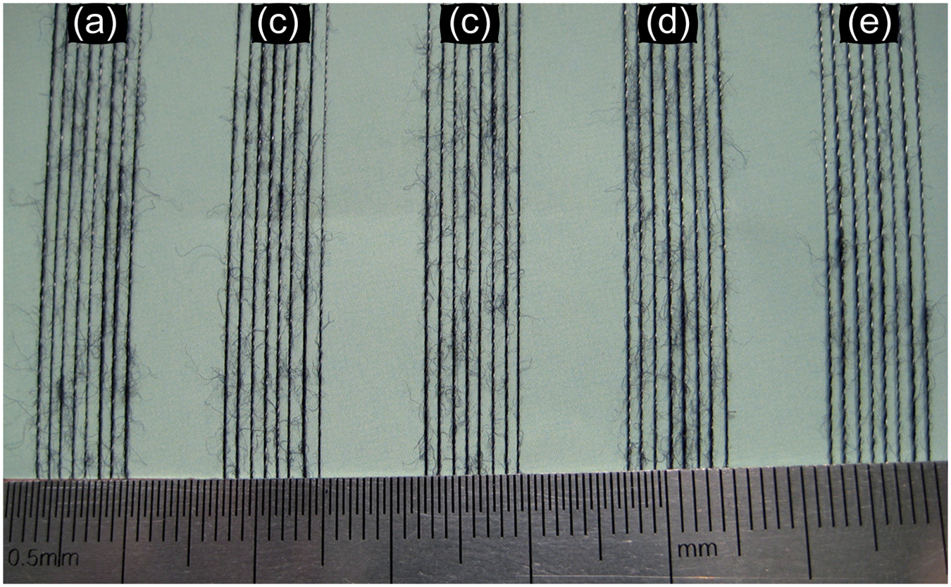
For a precise evaluation of yarn visual appearance, yarn hairiness was tested for all five composite yarns. Figure 5 shows that the siro core-spun yarn was hairier than the other composite yarns. This indicated that most staple fibers were still at the siro core-spun yarn sheath forming hairs, even though the filaments were not always at the core of yarn. For sirofil and ELS, filaments could tie the captured surface staple strand hairs tightly on to the composite spun yarn body; therefore, the hairiness of the sirofil or ELS yarn was lower than that of siro core-spun yarn listed in Figure 5. The 3rd ELS yarn was a bit more hairy than the yarns of the 1st ELS, 2nd ELS and sirofil, which might result from the loss of staple fibers during 1st ELS, 2nd ELS and sirofil spinning.
Comparisons of composite yarn hairs with various length ranges.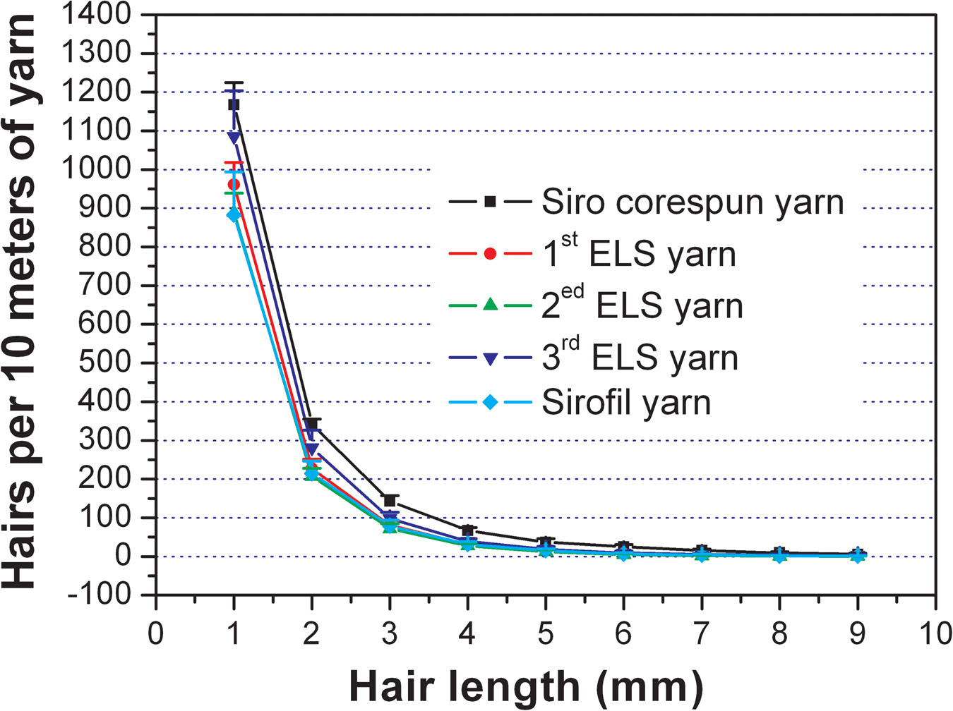
Unevenness comparison of different composite yarns
Unevenness parameters of different composite yarns
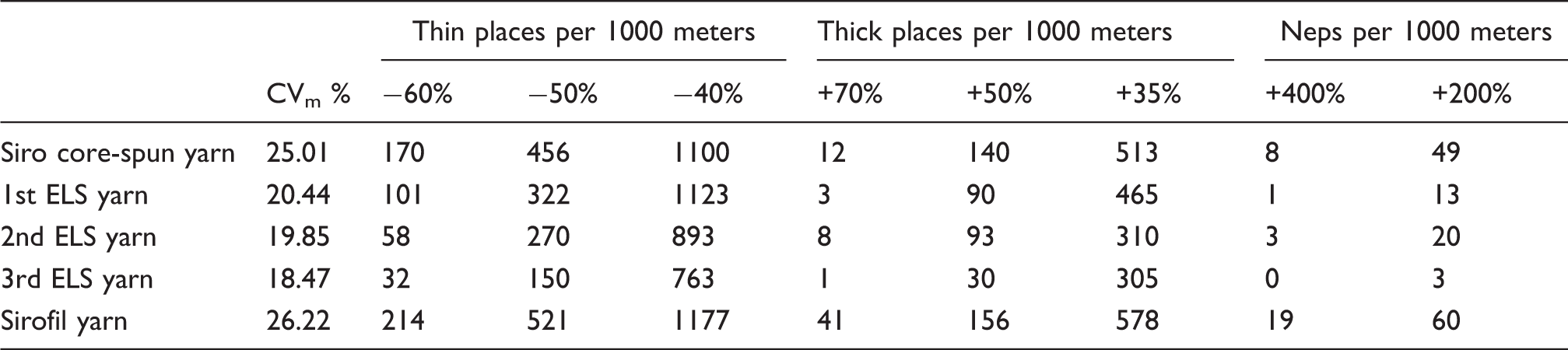
Irregular loss of fibers also led to a deterioration of yarn imperfections. Thus, other composite spun yarns had more thin places, thick places and neps than the 3rd ELS yarn (Table 3). The more irregular fiber loss might cause a more irregular yarn with higher unevenness and imperfections. The highest CVm and imperfections for the sirofil yarn probably indicated most irregular fiber loss occurs during the sirofil spinning with a suction flute working. Furthermore, irregular fiber distribution might be enlarged due to the slippage between the staple fiber and filament for sirofil yarns during the testing. Thanks to avoidance of the staple fiber visual loss and well-nesting in the composite yarn body, neps were reduced for the 3rd ELS composite yarn. In other words, the 3rd ELS was most suitable to produce very uniform composite yarn with among the five composite spinning methods.
Tensile properties comparison of different composite yarns
Tensile properties of different composite yarns

However, there was no statistically significant difference for breaking force and breaking work of the 1st ELS, siro core-spun and sirofil composite yarns. It did not correspond well to the huge yarn unevenness difference of the 1st ELS, siro core-spun and sirofil yarns. This might be because that the tenacity of filaments was so much higher than the staple fibers (Table 1) that filaments were the main contribution to the composite yarn tenacity; whilst staple fibers were the main contribution to composite yarn appearance and lengthwise variations.
Conclusions
Fiber trapping of embeddable and locatable spinning was compared with that of sirofil and siro core-spinning. Online pictorial analysis showed the 3rd ELS avoided the occurrence of the visual staple fiber loss that happened during the 1st ELS, 2nd ELS, sirofil and siro core-spinning. Different yarn weight results showed that the 3rd ELS yarn had a statistically heaver yarn weight than the 1st ELS, sirofil and siro core-spinning, which validated that the 3rd ELS had a high ability of fiber trapping to suppress fiber loss. Yarn appearance results showed that filaments were not entirely located in the core of the siro core-spun yarn. Siro core-spun yarn was more hairy than the other composite yarns, which indicated that filaments failed to capture and tie yarn surface fibers to reduce the hairiness for siro core-spun methods. Sirofil and siro core-spun yarn had higher value of CVm and yarn imperfections than the 3rd ELS yarn which might be probably due to that irregular fiber loss were depressed in the 3rd ELS system via positioning filaments and staple strands properly. In addition, the fiber loss would result in decreasing utilization of fibers in the yarn cross section. Thus, the sirofil, siro core-spun and 1st ELS yarn had a statistically lower tensile tenacity than the 3rd ELS composite yarn. In summary, the 3rd ELS had a high fiber trapping ability to produce an even and strong composite yarn.
Footnotes
Funding
This research was supported by the innovation funding from Donghua University, Songjiang District, Shanghai, China (grant number 101-06-0019040).
Appendix A: Statistical test results for yarn weights of different composite yarns at a significance level of 0.05
Means for groups in homogeneous subsets are displayed. Student–Newman–Keuls, uses harmonic mean sample size of 3.000.
VAR00001
VAR00002
N
Subset for alpha = 0.05
1
2
3
4
SNK
a
5. sirofil yarn
3
2.5492
1. siro core-spun yarn
3
2.5833
2. 1st ELS yarn
3
2.6096
3. 2nd ELS yarn
3
2.6817
4. 3rd ELS yarn
3
2.6928
Sig.
1.000
1.000
1.000
0.241