
Abstract
This study reports a numerical analysis on embeddable and locatable spinning systems. The finite element method is used to quantify the relationship between the tension and twist of staple strands and the spinning parameters. The model was constructed using the three-dimensional beam element, which is capable of simulating the stretching, bending and torsion behavior of the filament and the staple strand. It was found that the staple strand shares far less load (around 13.8%) than the filament during the spinning process. The twist is mainly distributed on the composite yarns and less on other zones. The pretension of the filament, the filament–strand distance ratio, the twist of the composite yarn and the material fed-in velocity were investigated for their influence on the tension and twist of the staple strand. Numerical predictions showed that higher filament tension and filament–strand ratio lead to less load and more twist on the staple strand. This is beneficial in producing stronger and smoother yarns and avoiding end breakages. It was also determined that strand tension and twist increase with an increase in composite yarn twist and a decrease in material fed-in velocity.
The mechanical performance of the ring-spinning triangle is a field of great interest, which is closely associated with the properties of the resultant yarn as well as end breaks during the spinning process. Due to the limitation of experimental approaches, some behaviors of the triangle zone, such as fiber tension and torque, are difficult to obtain. Therefore, researchers tend to resort to the theoretical method. The force balance method was firstly introduced in studying the twist irregularity of cotton and worsted spun yarns by Fujino. 1 Similar methodologies were then employed in predicting fiber migration, 2 yarn breakage rate 3 and the strength of the triangle. 4 Along with the force method, the energy method, which works on the principle of minimum potential energy, is has gained ground over recent years. Shaikhzadeh Najar 5 built a numerical model to simulate fiber tension in a symmetric spinning angle under different yarn counts, twist angles and spinning tensions. Hua et al. 6 then modified Shaikhzadeh Najar’s model to study the tension and toque in an asymmetric spinning triangle. In their research, fiber bulking in the middle position was firstly taken into consideration. Other similar works on studying symmetric and asymmetric spinning triangles using analytical models include Feng et al., 7 Su et al. 8 and Liu and Su.9,10 It has been pointed out that although these types of models do not require a full description of the spinning triangle geometry, fiber torsion is not considered. The advent of computerization enables this problem to be solved using the finite element (FE) method. The analysis of the symmetric triangle 11 and the asymmetric triangle12–14 are both covered. The FE method avoids the mathematical complexities in the energy method without influencing the accuracy of the theoretical predictions.
Although there is no shortage of literature on the modeling of the ring-spinning triangle, little attention has been paid to the theoretical work of embeddable and locatable spinning (ELS). Some relevant publications focus on the force and torque balance model of two-strand spinning (Siro spinning), which forms the building blocks of ELS spinning.15–21 Emmanuel and Plate 15 established a quasi-static model to describe the process of Siro spinning, yet the force balance equations were unsolved as there are fewer variables than in the independent equations. By combining momentum equations, mass conservation and energy conservation equations, He et al. 16 claimed that the solutions could be obtained. Then, a dynamic model was developed to study the trajectory and position of the yarn convergence point under different conditions.17,18 In addition, yarn vibrations and resonance in Siro spinning were also investigated using the variational iteration method. 19 In these models, the author converted the conventional quasi-static model to a dynamic process, and hence a number of phenomena observed on the practice run could be taken into consideration and be presented. Based on the aforementioned quasi-static model on Siro spinning, Wang et al. 20 used force and torque balance to further investigate the shape of the ELS yarn formation triangle. It has been found that the angle at the convergence point is closely associated with composite yarn twist, other parameters being equal.
Perhaps the most important problem of ELS spinning is end breakage due to fewer staple fibers in the strand zone, especially for high-velocity spinning. 21 In practice, the roving will be compressed and drafted by the front top and bottom roller to form a staple strand. The resultant strand is very weak and tends to fail if the tension exceeds its strength. The twist transferred from the bottom enables the strand to form a tiny triangle and increase the cohesive force, and hence increase the strength of the strand. Thus, it is necessary to investigate the tension and twist on the staple strand in the hope of providing guidance for optimized spinning processing parameters and to avoid yarn breakages. In this research, a comprehensive understanding of this zone will be developed in numerical models. The FE method will be employed to quantify the relationships between the tension and twist on staple strands and a number of practical parameters, including filament pretension, the filament–strand distance ratio, composite yarn twist and material fed-in velocity. In addition, the influence of filament pretension and the filament–strand distance ratio on the properties of their composite yarns are reflected and analyzed for model validation.
Embeddable and locatable spinning
The ELS system was first introduced by Xu et al.
21
for the production of super-fine and high-quality yarns. The ELS system is essentially a combination of two siro-fil spinning systems, and is shown in Figure 1. It can be seen that two filaments, F1 and F2, form a large triangle ΔN1N2C with the front roller nip line. Two staple strands, S1 and S2, were inserted within ΔN1N2C and twisted together with the outside filaments to form reinforced strands like siro-fil spun yarns CC1 and CC2. The two reinforced strands are then twisted again at the convergence point C to produce the final composite yarn. Due to the shape of the yarn formation triangle ΔN1N2C, it is believed that the majority of the spinning tension is shared by the filaments located outside. In this regard, inside staple strands are subjected to far less load in the ELS system than that in conventional ring-spinning or siro-fil spinning systems. That is, the number or the length of fibers in the staple strand could be reduced. The inventors have successfully produced super-fine wool yarns on an experimental machine using a staple strand containing only 10 fibers. “Yarn breakages” were less likely to occur and also yarn evenness was greatly improved according to the experimental data. More often than not, filaments are made of water-soluble materials, such as polyvinyl alcohol, aiming to dissolve the filament component from the composite yarn. Another benefit of the ELS system is that smoother yarns could be manufactured. Hairs of the staple strands are effectively embedded into the composite yarn due to the double-twisting process.
Schematic diagram of the embeddable and locatable spinning system.
21

Finite element model
The principle of the FE model and ABAQUS
The fundamental principle of the FE model is converting a complex continuum problem to a number of comparatively simpler discrete problems. With the aid of digital computing, discrete problems can be solved readily and the required accuracy could be achieved. The application of the FE model in engineering design involves eight steps 22 as follows. Step 1: discretize and select element types. In this step, a continuum is subdivided into a finite number of elements, which is specified by a finite number of parameters, such as material density and elastic/plastic behavior. Step 2: displacement function selection. Different types of elements require their corresponding displacement function, linear or quadratic, to represent the displacement as a function of coordinates. Step 3: define the strain/displacement and stress/strain relationships. The relationships could be readily obtained from physical equations and geometric equations. Step 4: drive the element stiffness matrix and equations. More often than not, the principle of minimum potential energy, the principle of virtual work and Castigliano’s theorem are used for the element stiffness matrix. Step 5: Assemble the single element stiffness to the global stiffness matrix and introduction boundary conditions (BCs) to remove the displacement of the rigid body. Step 6: calculate the degree of freedom. Step 7: solve the element’s strain and stress. Step 8: interpret the results. Among the above procedures, discretization is done manually and the rest of the steps are carried out with the aid of a computer program. In this research, commercial package ABAQUS is used. This software was originally released in 1978 by HKS and offers a wide range of capabilities for the simulation of linear and nonlinear applications. ABAQUS contains an extensive library of elements that can model virtually any geometry. As a result, the constituent filaments and staple strands of ELS are considered as three-dimensional (3D) elastic beam elements in order to better simulate the yarn twisting process.
Finite element model for ELS
Figure 2 shows the top view of the FE model of the ELS yarn formation zone. In this research, the curvature of the front bottom roller surface is not taken into consideration. It can be seen that two filaments form the large spinning triangle below the front roller nip line, aiming to protect the inside staple strands. It is reasonable to model the filaments using the beam element, as the dimensions of the cross-section are small compared to the length along the filament axis. In the FE model, a single beam element has six degrees of freedom, indicating that it is able to be subjected to stretching, bending and torsion, which corresponds to the material responses in the real spinning process. Two staple strands are symmetrically fed into each side within the large spinning triangle. Technically, these strands are formed by a number of staple fibers and could not be fully modeled due to their discontinuity. In addition, the comparatively lower tensile strength in a staple strand is caused by its weak cohesive and frictional force. It was attempted to use the discontinuous beam element to simulate individual staple fibers in the strand. The frictional force could be achieved by adding connectors between the neighboring elements, but the results were not satisfying. The main problem is that it is difficult to define the mechanical behavior of the connector, leading the strand model to be either too stiff or too loose. Since the continuous-beam-element forming triangle model in Li et al.
11
and Liu and Su’s work
12
provides a decent numerical prediction for fiber tension and torque during the ring-spinning process, it is acceptable to simplify the staple strand into filaments. In practice, a twist inserted at the convergence point would transfer all the way upward to the two reinforced strands, and thereafter to the filaments and staple strands. This would inevitably form a spinning triangle zone right beneath the front roller nip on staple strand. In this research, as the twist on strands is small, the triangle zone is not considered in the FE model.
Finite element model of embeddable and locatable spinning (ELS).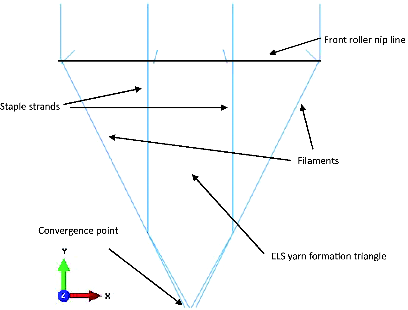
Apart from the beam element, an alternative is to use the continuum element for the whole process. Attempts have also been made and it seems that this approach causes more problems. For one thing, running a job containing continuum elements seems to be more computer costly than using beam elements; more importantly, bottom end twisting leads to non-convergence, and hence the model fails to give decent numerical predictions. The linear density of the undrafted roving is 320 tex and the drafting ratio is 29. The diameter of the strand cross-section could be derived from that of the undrafted roving (2 mm), which is around 0.07 mm. The fiber in use is cotton. Since the FE model does not support low elastic modulus and orthotropic material value, the elastic behavior is isotropic and the modulus of the strand is set to be 6 GPa (the initial modulus of cotton fiber) 23 and Poisson’s ratio is set to be 0.3. It seems apparent that the density of the strand could not be directly taken from that of cotton fiber, as fibers do not integrate in a compact state in a strand. The density of the cotton strand in the model is considered to be around 0.1 g/cm3, which is the density of an undrafted roving.
An angular velocity at the X–Y-plane and a vertical translational velocity along the Z-axis are applied to the bottom end. The angular velocity determines yarn twist and the translational velocity is technically the yarn spinning velocity. The resultant composite yarn on the bobbin has a twist of 800 turns/meter. The yarn twist, however, between the convergence point and the yarn guide (not plotted in Figure 2) is about one third of the total twist (266 turns/meter) due to the blockage effect of the yarn guide. According the strand fed-in velocity of 12 meter/min, the angular velocity, therefore, is set to be 334 radian/second. Since the front top and bottom rollers firmly constrain the displacement of filaments and strands in practice, the model section above the front roller nip line is only allowed to displace along the Z-axis, and the other five degrees of freedom are not allowed. The aforementioned two requirements are difficult to obtain as the length of the model above the front roller nip line changes with every time increment as the job runs. A practical method is to set multi-step BCs. This means that a job is divided into finite number of steps and each step corresponds to a BC. For instance, in Figure 3(a), only the BC in the yellowed part is active during the corresponding steps; the rest stays inactive. In a practice run, pretension is applied on the filaments for strand protection. Filament pretension is achieved by keeping the top end inactive for the first few time steps in simulation. The action on the bottom end will eventually increase the tension to the required level.
Multi-step boundary conditions for (a) step 1; (b) step-2; (c) step-3; (d) step-4. (Color online only.)
In the model, both the filament and the strand are considered to be isotropic. The filament is 3.6 tex polyester with a diameter of 0.05 mm. The isotropic material has a modulus of 100 cN/dtex (engineering modulus =18.3 GPa) and a Poisson’s ratio of 0.3. Material density is 1.38 g/cm3. The distance between the two side-filaments is 10 mm and that between the two inside strands is 3 mm. The height of the large triangle zone is 10 mm. The filaments have a pretension of 2 cN and the strands have no pretension.
Results and analysis
Figure 4 shows the contour plot of Von Mises Stress distribution on both filaments and strands during the ELS process. Von Mises Stress σ′ is a combination of the three primary stresses σ
x
, σ
y
, σ
z
and the shear stresses τ
xy
, τ
yz
, τ
xz
. The Von Mises Stress can be expressed as
Contour plots of Von Mises Stress distribution for embeddable and locatable spinning at (a) 0 ms; (b) 5 ms; (c) 10 ms; (d) 15 ms; (e) 20 ms; (f) 25 ms.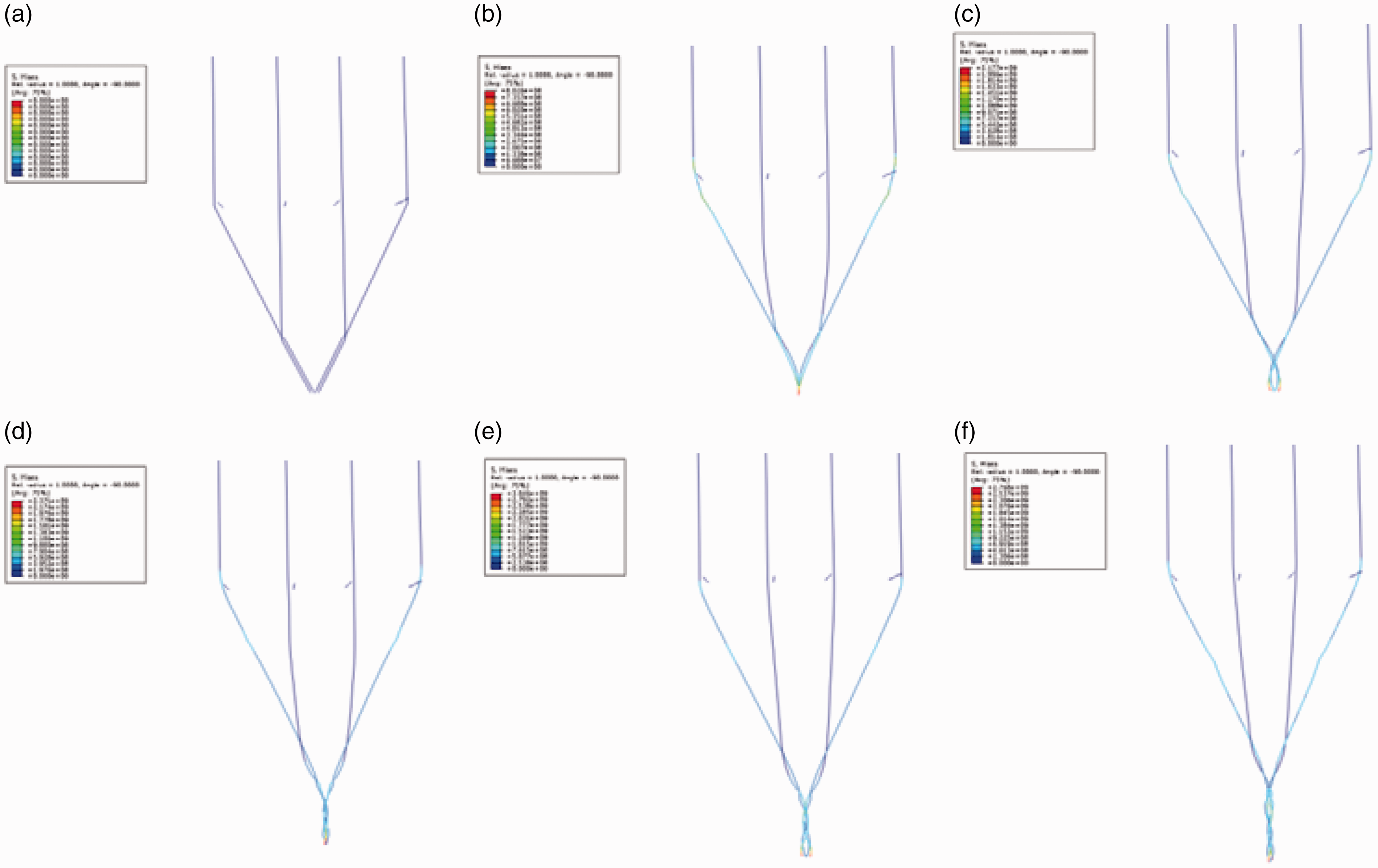

It can be seen in the figure that the stress is mainly concentrated below the convergence point and on the filaments. Elements were selected from the filament and strand respectively, and the stress was presented as a function of time. The raw data was processed using antialias filter and was expressed in centinewton. It was found in Figure 5 that there is an initial increase of tension from 0 to 2 cN on the filament, indicating the transformation from a static state to a dynamic state. The average tension on the strand during the period is around 0.27 cN, which is 13.8% that of the filament. The numerical results collaborate with the practical work done in the previous work,
21
suggesting that the stable strands were protected by the side-filaments and withstand far less spinning tension during the yarn formation process. This enables super-fine composite yarns to be manufactured.
Time history of normalized tension on filaments and strands.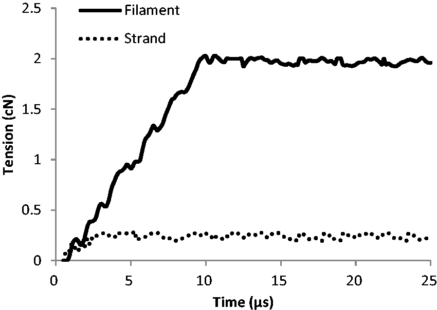
Twist inserted at the bottom end tends to transfer all the way up to the front roller nip line. The twist will firstly be shared by two reinforced strands, and then be sub-shared by filaments and strands. Due to the constraint of the front rollers, material behind the front roller nip line will not be affected. According to Treloar,
24
twist, n, is obtained by

It is revealed from Equation (2) that yarn twist is directly related to the angular rate of rotation, which is essentially rotational displacement. In order to investigate yarn twist transfer, the rotational displacement of four zones, namely the zone of composite yarn, the zone of the reinforced strand, the zone of the filament and the zone of the strand, were studied. Figure 6 shows the four zones in the FE model. In each zone, four reference points were monitored for their rotational displacement. Figure 7 shows the results at 25 ms. Based on Equation (2), the twists are calculated by dividing the gradient of the equation of the corresponding regression line by 2π, which gives 267 turns/meter for the zone of composite yarn, 95.5 turns/meter for the zone of reinforced strand, 67.6 turns/meter for the zone of filament and 75 turns/meter for the zone of strand. It is difficult to validate the numerical predictions with the experimental result due to the high spinning velocity of ELS yarns. We are planning to perform practical running using four types of strands and filaments with different colors, hoping to observe the level of twist with the help of a high-speed camera. The results will be published in future papers.
Angle of rotation at different points along the path of the filament and the strand at 25 ms. Rotational displacement at 25 ms in (a) the zone of the composite yarn, (b) the zone of the reinforced strand, (c) the zone of the filament and (d) the zone of the strand.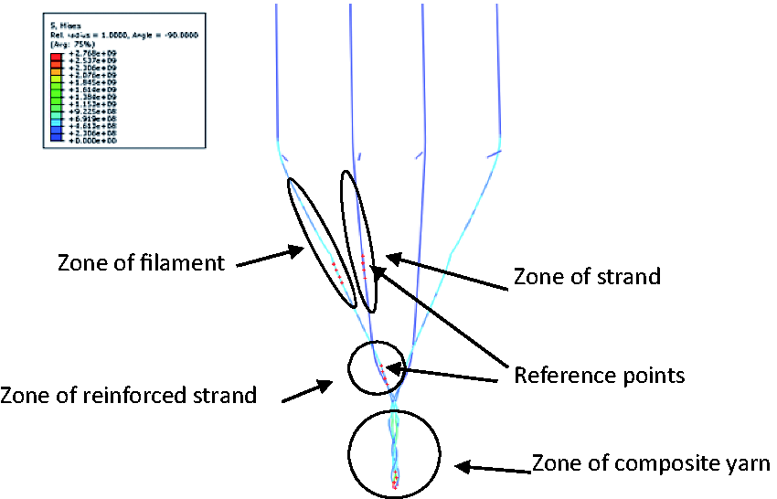

It seems that twist is more densely distributed at the zone of composite yarn than at other zones. This could be because the forces on the reinforced strands cause stress concentration on the composite yarn (Figure 4), and therefore limit the twist transferred to other zones. Due to the fact that tension is higher on the staple strand than on the filament, stress is less concentrated on the reinforced strand. As a result, twist transferring is not constrained under this condition. In addition, a slightly higher level of twist on the staple strand than on the filament could be associated with the geometry of the yarn formation triangle. Since staple strands are located inside the triangle, they are shorter in length than filaments. It follows that the value of z is lower for the staple strand in Equation (2), and hence it has higher twist. In this paper, the influencing factors, such as filament pretension, the filament–strand distance ratio, the twist of the composite yarn and material fed-in velocity, will be investigated, aiming to develop an understanding of their relationship with the tension and twist on the staple strand. The numerical predictions will hopefully reduce the probability of strand breakage during high-speed manufacturing and produce super-fine ELS yarns.
Effect of filament pretension
Figure 8 shows the numerical predictions on strand tension and twist influenced at filament pretensions from 0.40 to 3.2 cN. It reveals that an increase in filament pretension would inevitably reduce strand tension, and vice versa. The curve for the strand twist increases from 0.4 cN, reaches a peak at 2 cN and almost levels off beyond that point. This is because when the staple strand is in low tension, it tends to wrap around the filament and have more rotational displacement, and hence a higher level of twist. Upon further lowering, the strand tension would reach a threshold value, and the benefit in twist increase is reduced. In addition, when the filament tension increases, the protection zone triangle deforms, leading to a reduced strand length. Since the number of turns on the strand does not change, the twist would inevitably increase. Beyond the threshold point, the protection zone triangle does not change any more, and hence the leveling-off of the twist curve. Table 1 reveals the influence of filament pretension of yarn properties in the experiment. Combed cotton roving of 320 tex and polyester filament of 4.4 tex were used as raw materials. An HF41-01-4 multi-functional spinner was in use for the spinning process. Filament tension was controlled using an SFY13 filament tensioner. Composite yarn strength, evenness and hairiness were tested on a YG(B)021DX single yarn tensile machine, a YG135E evenness tester and a YG172A hairiness tester, respectively. The filament tension was selected from 0.49 to 2.45 cN during the spinning process using an SFY13 filament tensioner.
Finite element predictions on strand tension and twist as a function of filament pretension. The effect of filament pretension on yarn properties
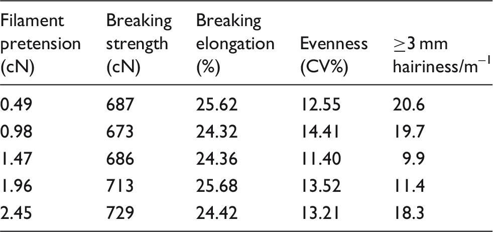
It could be seen that yarn strength and breaking elongation seem to be similar at different filament pretensions, but the best evenness and hairiness is given by 11.41% and 9.9 (≥3 mm hairiness/m–1) at 1.47 cN. This could be explained as follows: if the filament pretension is low, the staple strand has a comparatively high tension and low twist, which is shown from numerical prediction in Figure 8. Although the staple strand could be wrapped by the filament, the short fibers on the outer periphery of the strand could not be properly embedded in the yarn body by the self-twisting effect, therefore resulting in higher evenness and hairiness values; on the other hand, if the filament is in high tension, the resultant composite yarn could not be wrapped by the filament in a good manner. Consequently, yarn evenness and surface roughness deteriorate as well. As a result, the optimum value seems to be 1.47 cN for best evenness, from the experimental results.
Effect of the filament–strand distance ratio
The ratio of the distance between two staple strands by the distance between two filaments is investigated for its effect on strand tension and twist. It is shown in Figure 9 that if the strands are located in the middle of the yarn formation triangle, which means that the value of the distance ratio is low, staple strands are in high tension and low twist, and vice versa. This could be attributed to the change of angle between the filament and the staple strand. Figure 10 shows contour plots of ELS at distance ratios of 0.1, 0.3, 0.6 and 0.9, the corresponding angles of which are found to be 20.26°, 17.8°, 14° and 9.73°, respectively. The online photos of the corresponding distance ratio are shown in Figure 11, which used four drafted rovings for demonstration. Although the pictures of the distance ratios of 0.1 and 0.3 are similar, the change in the protection at the ratios of 0.6 and 0.9 is clearly identifiable.
Finite element predictions on strand tension and twist as a function of the distance ratio. Contour plots of embeddable and locatable spinning at distance ratios of (a) 0.1, (b) 0.3, (c) 0.6 and (d) 0.9. Online photos of the yarn formation zone at distance ratios of (a) 0.1, (b) 0.3, (c) 0.6 and (d) 0.9.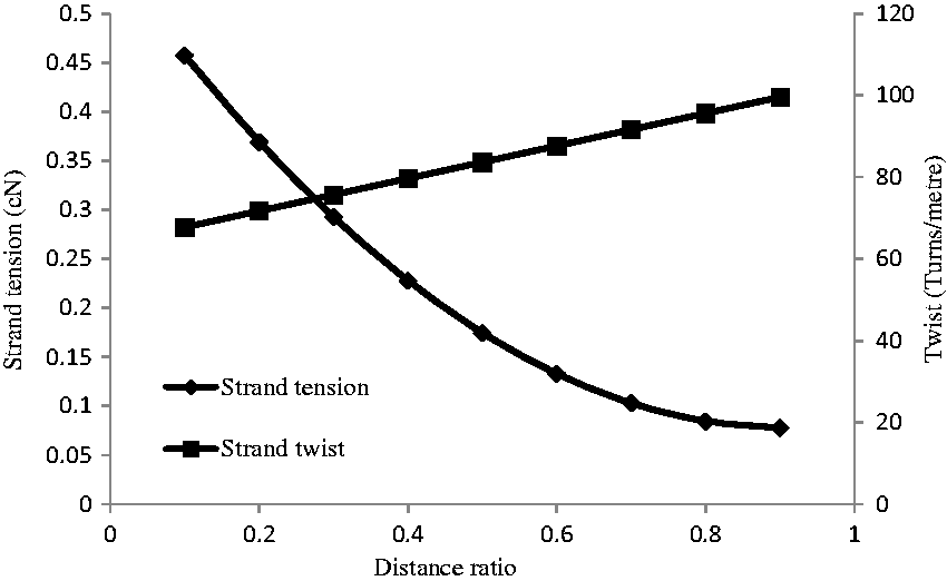


According to force balanced equation
21
Schematic illustration of the protection zone in embeddable and locatable spinning.
21
Effect of distance ratio on yarn properties Note: the distance ratio of 0 indicates that there is only one staple strand in the middle of the spinning triangle. Microscopic observation of yarns with distance ratios of (a) 0.6, (b) 0.5, (c) 0.33 and (d) 0.


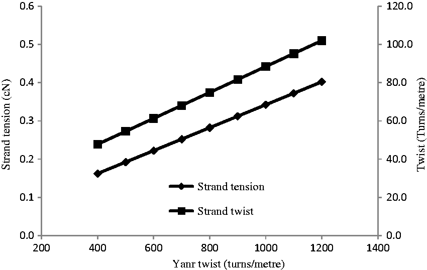
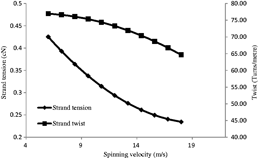
Effect of composite yarn twist and material fed-in velocity
Figures 12 and 13 show the strand tension and twist as a function of composite yarn twist and material fed-in velocity. It can be seen in Figure 14 that staple strand twist and tension increase with composite yarn twist. Apparently, it seems that more twist would be transferred to strand with an increase in composite yarn twist. This also increases the cohesive force between individual staple fibers, and hence strand tension increases. It can be seen in Figure 15 that strand tension and twist decrease concave upward and downward with an increase in material fed-in velocity, respectively. According to the equation to calculate composite yarn twist, t
Finite element predictions on strand tension and twist as a function of composite yarn twist. Finite element predictions on strand tension and twist as a function of material fed-in velocity.
Conclusions
This paper contributes to a numerical study of the yarn formation angle in ELS using FE models to quantify the relationship between the mechanical behaviors of the staple strand and a couple of influencing factors in practice. The tension and twist of the staple strand, which play important roles in the end breakage rate and yarn properties, are studied. Some numerical predictions are compared with experimental data for validation. FE models show that the tension of the staple strand is around 13.8% that of the filament, and the twist on staple yarn is slightly higher than that on the filament. The fact that twist is mainly distributed in the zone of composite yarn could be attributed to the stress concentration, which is probably caused by the loading effect of the reinforced strands. In this regard, twist transfer is constrained. It has been found that an increase in filament pretension and the filament–strand distance ratio lead to a decrease in strand tension, which is beneficial in spinning super-fine yarns and avoiding end breakage. The twist of the staple strand is increased due to the lower tension, and therefore a smoother and stronger ELS yarn could be obtained from practical work. In addition, the twist distributed on the staple strand increases with composite yarn twist and decreases with material fed-in velocity. It is interesting to note that if it is the tension of the staple strand that is directly influenced by parameters such as filament pretension and distance ratio, these parameters would have a reverse influence on the strand twist; if it is the twist of the strand that is directly determined by parameters such as composite yarn twist and material fed-in velocity, these parameters would have a similar influence on strand tension. Additional work is underway to further investigate this problem, aiming to provide guidance for optimizing ELS spinning.
Footnotes
Declaration of conflicting interests
The authors declared no potential conflicts of interest with respect to the research, authorship and/or publication of this article.
Funding
The authors disclosed receipt of the following financial support for the research, authorship, and/or publication of this article: This research is funded by Ministry of Education, Hubei province (Grant Number: D20171602).