
Abstract
Multiwalled carbon nanotube/poly(m-phenylene isophthalamide) (MWNT/PMIA) nanofibers mats with different MWNT contents were successfully prepared by electrospinning. Scanning electron microscopy (SEM), transmission electron microscopy (TEM), x-ray diffraction (XRD) and a thermal gravimetric analyzer (TGA) were used to characterize the morphology and properties of nanofibers. The results showed that the nanofiber diameter is reduced with increasing MWNT concentrations and the surfaces of the MWNT/PMIA nanofibers becomes rough compared with those of the virgin version. The MWNTs are well dispersed in the nanofibers and well-aligned along the nanofibers. The dosing level of MWNTs seems to show only minor influences on both the crystalline structure and the initial degradation temperature of the nanofibers. While the mechanical properties of the nanofiber mats are generally improved with the addition of MWNTs. The striking improvement occurs at the loading of 0.6 wt% with the increase of tensile strength at breakage by ca. 86%.
Introduction
The electrospinning process was invented by Formhals in 1934 (USP 1975504) and since then, especially during the past decade, this process has received a great deal of attention. Electrospinning technique is a flexible and effective way to prepare nanofibers with high speed, simple device and low cost. The resultant polymer nanofibers are featured with a large specific surface area and ease of functionalization for various purposes. These polymer nanofibers can be used as reinforcing fibers in composites, sensors, filtration materials, biomedical materials, molecular nanoelectronics, etc. 1 – 7 Many polymers have been electrospun in solutions or molten states, and a number of review articles have been published.2,7
Carbon nanotubes (CNTs) have been the focus of numerous investigations since they was discovered in 1991, 8 this is because CNTs possess many excellent properties, such as exceptional mechanical properties, high thermal stability, superb electrical conductivity and strong chemical resistance. These properties have inspired interest in trying CNTs as a filler in polymer composites to improve the properties of polymer materials. 9 – 11 A large number of polymers have been explored in electrospinning nanofibers that contain CNTs, such as nylon 6, 12 polyacrylonitrile, 13 – 15 polyvinyl alcohol, 16 poly(ethylene oxide),16,17 polycaprolactone. 18 The dispersion and alignment of CNTs in the polymer matrix are usually difficult since CNTs are easy to bundle together and agglomerate due to van der Waal’s force interaction. 19 The well-dispersed and well-aligned CNTs in polymers were, however, often desired for maximizing improvement of the mechanical properties of CNTs/polymer composites. 20 Electrospinning was supposed to be a potential method for isolating and debundling CNTs. 21 In fact, recently the electrospinning technique has been constantly attempted for the alignment of CNTs in the polymer matrix, due to the high extension and high elongation during the whipping process.14,15,17,18,22
Poly(m-phenylene isophthalamide) (PMIA) has especially prominent thermostability, high flame retardancy, self-extinguishing characteristics, electrical insulation ability, chemical resistance and mechanical properties, etc. So PMIA is widely applied in special protective clothing, high temperature filter materials, electrical insulating materials and honeycomb structure wainscoting materials, etc. 23 – 25 There have been very few studies focused on the electrospinning of PMIA nanofibers. Yao et al. obtained PMIA nanofibers with preferable morphology and good mechanical properties in the lithium chloride/N,N-dimethylacetamide (LiCl/DMAc) solvent system. 26 The effect of thermal treatment on the properties of PMIA nanofiber mats was focused as well. 27 PMIA nanofiber yarn was produced by self-bundling electrospinning and alignment of nanofibers in the yarn was obtained. 28
In this study, the PMIA was dissolved in LiCl/DMAc solvent system, and then mixed with the MWNT/DMAc solution, finally MWNT/PMIA nanofiber mats were made using the mixed solutions by electrospinning. The MWNTs were grafted with a non-ionic surfactant, Triton X-100, to improve dispersion in the PMIA solution. The effects of the MWNTs on the nanofiber morphology and mechanical properties were investigated in detail.
Materials and methods
Materials
Commercial PMIA fibers (tensile strength at breakage was ca. 4.5 cN/dtex, and density 1.37–1.38 g/cm 3 ) were provided by Yantai Spandex Co. Ltd. (China). MWNTs (diameter < 10 nm, length 1–2 µm, purity 95%–98%) were purchased from Shenzhen Nanotech Port Co. Ltd. (China). Anhydrous lithium chloride (LiCl) was supplied by Shanghai Jufeng Chemical Scientific Co. Ltd. (China). Triton X-100 (C8H17C6H4(OCH2CH2)n, n ≈ 10), DMAc and N,N-dimethylformamide (DMF) were purchased from J&K Scientific Co. Ltd. HNO3 (65%) and H2SO4 (95%) were supplied by Shanghai Chemical Reagent Co., Ltd. (China). Tetrahydrofuran (THF) and SOCl2 were purchased from Sinopharm Chemical Reagent Co., Ltd. (China). All the chemicals were of analytical reagent grade.
Functionalization of MWNTs
Firstly, MWNTs were added into the solvent mixture of HNO3 and H2SO4 (v/v = 1:3), and the solution had a 4 h-ultrasonic treatment at room temperature. Then the MWNTs were separated from the mixture solvent by centrifugation and further purified with deionized water until the pH value reached 7, and finally MWNTs were dried in an oven at 90°C. Afterwards, the MWNTs were added into the solution of SOCl2 in DMF, and stirred for 24 h at 65°C, the MWNTs-COCl were obtained after washing with THF, and then dried. The MWNTs-COCl were put into the solution of Triton X-100 in DMF, and the solution was stirred under N2 atmosphere at 120°C for 48 h. The MWNTs grafted with Triton X-100 were obtained after washing with DMF, and dried for the further use. 15
Preparation of spinning solution
LiCl was dried in a vacuum dryer at 120°C for 2 h. Firstly, the dried LiCl was added into DMAc and stirred till it was dissolved completely, and followed by putting PMIA into the solution. The solution was stirred at 90°C until transparent. Meanwhile, MWNTs-Triton X-100 were added into DMAc solvent and ultrasonicated for 1 h. Finally, the two solutions were mixed with different MWNT mass fractions (0%, 0.2%, 0.6%, 1.0%) after 1 h ultrasonic treatment. The mass fractions of LiCl and PMIA in the solution were 3% and 12% respectively.
Electrospinning
The spinning apparatus was a Nanofiber Electrospinning Unit (KATO TECH Co. Ltd., Japan). Spinning parameters were as follows: inner diameter of spinneret 0.45 mm, voltage 23 kV, collecting spinning distance 11 cm, solution flow rate 0.26 ml·h−1, spinneret scan speed 14 cm·min−1, collector rotating speed 6 m·min−1.
Measurements
Spinning solution viscosity and conductivity were measured respectively by AR2000 rheometer (TA Instruments, USA) at 25°C with awl diameter 40 mm, and DDP-220 conductivity meter (Shanghai Precision & Scientific Instrument Co. Ltd., China), each sample was measured five times and the average value was calculated.
The morphologies of the electrospun MWNTs/PMIA nanofiber mats were observed by scanning electron microscopy (SEM) (Hitachi S-4800, Japan). The mean diameter of the fibers was measured by the image analyzing system (Image-Pro Plus 5.0); 100 measurements were taken, then the average value was calculated.
X-ray diffraction (XRD) patterns of powdered samples were obtained by using an X’Pert Pro MPD x-ray diffraction system (PAN analytical, Holand). A voltage of 40 kV and a current of 40 mA using a CuKα radiation (λ = 0.154 nm) were used. The diffraction degree 2θ ranged from 5° to 45°.
Thermal stability of the nanofibers was measured by using an SDT Q600 simultaneous differential scanning calorimeter/thermal gravimetric analyser (DSC-TGA) instrument (TA Instruments, USA). The sample was ramped at 10°C/min from room temperature to 1000°C under a nitrogen atmosphere.
The dispersion and alignment of MWNTs in the MWNT/PMIA nanofibers were inspected by transmission electron microscopy (TEM) (Tecnai G2 F20 S-Twin, 120KV, USA).
The mechanical properties of the nanofiber mats were tested by Instron 3365 mechanical testing machine with a gauge length of 10 mm, crosshead speed of 10 mm/min, and initial tension 0.2 cN. The sample quantity was 10 for each of the nanofiber mats, and the size of each sample is 50 mm × 2 mm. The tensile strength at breakage was calculated by the mean of 10 samples. All of the samples were conditioned in a laboratory environment (20 ± 1°C and 65 ± 3%) for 24 h before testing.
Results and discussion
Surface morphology
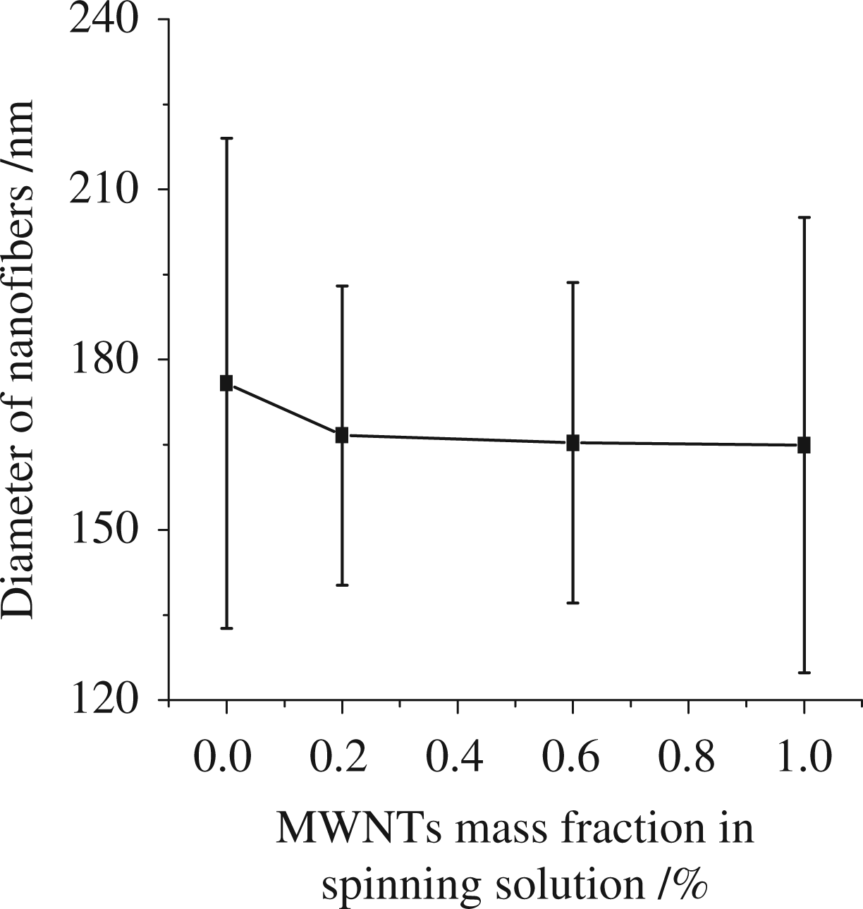
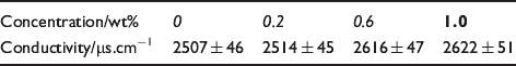
Figure 1 shows SEM images of MWNT/PMIA nanofibers electrospun from the solutions at the MWNT concentrations of 0 wt%, 0.2 wt%, 0.6 wt%, 1.0 wt%, respectively. The results indicated that the nanofibers were uniform and smooth, and with no beads. The average diameter of the nanofibers is shown in Figure 2 and decreased by a small amount with the increase of MWNT contents. Theoretically, the morphology and the diameter of the nanofibers are affected by the polymer solution properties (such as viscosity, electrical conductivity, etc).3,5 With increasing MWNT concentrations, the spinning solution viscosity shown in Figure 3 did not present significant changes, but the electrical conductivity, as listed in Table 1, was increased, which would cause the reduced diameter.
SEM images of the nanofibers at the MWNT concentrations (a) 0 wt%, (b) 0.2 wt%, (c) 0.6 wt%, (d) 1.0 wt%. The diameter of the nanofibers at different MWNT concentrations. Spinning solution viscosity at different MWNT concentrations. Conductivity of spinning solutions at different MWNTs concentrations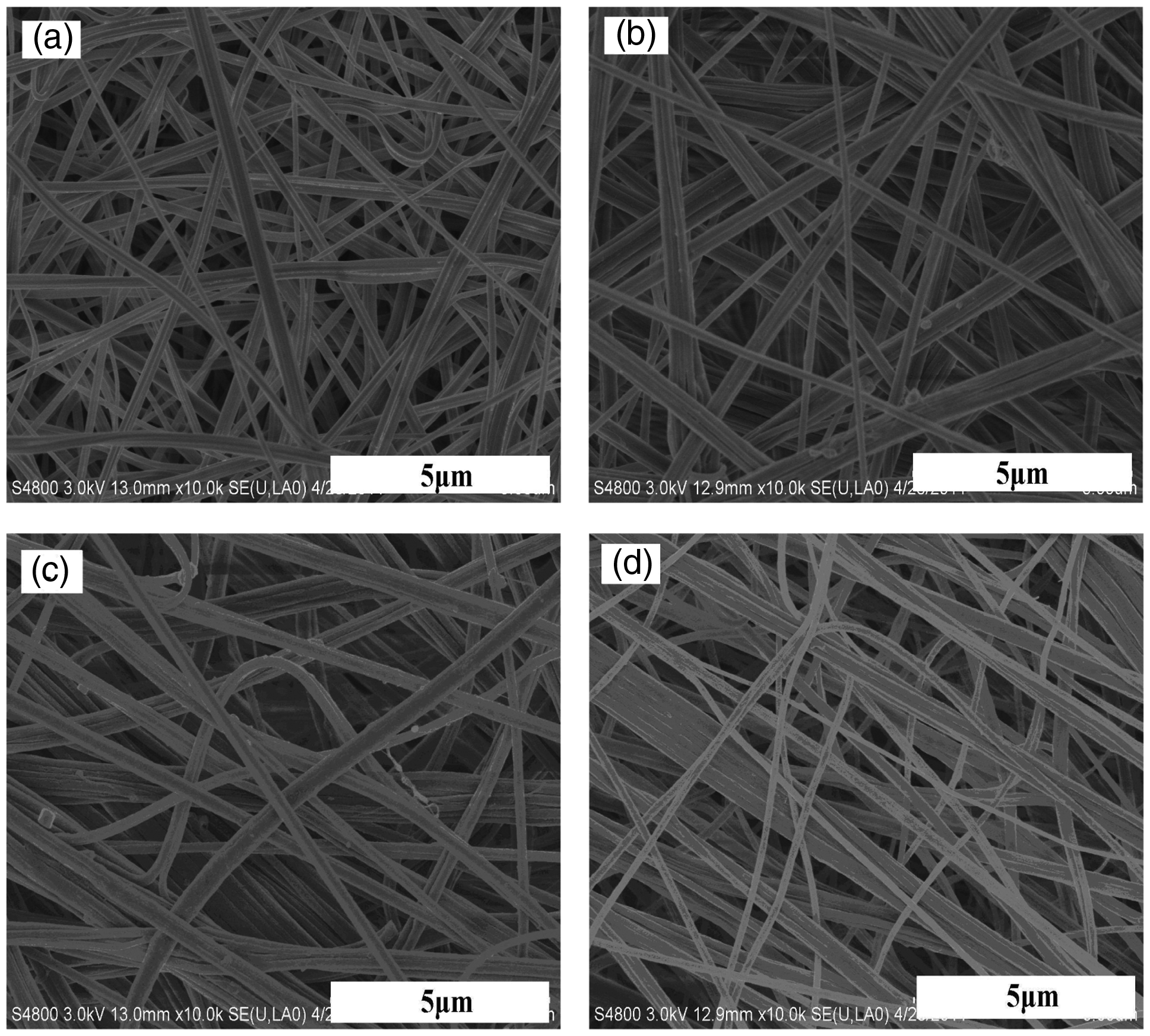

Crystal structure
Figure 4 shows the XRD spectra of the commercial PMIA fibers and the electrospinning nanofibers. The crystal cell of PMIA is triclinic.
29
The commercial PMIA fibers show three diffraction peaks at the scattering angle 2θ of ca. 17.2°, 23.6° and 27.3°. However, the electrospinning pure PMIA nanofibers (i.e. MWNTs 0 wt%) exhibited a diffraction peak at the angle 2θ of ca. 24.3°, and a reduced peak intensity, namely, a decrease of the crystallinity of nanofibers. The degenerative peak and weak intensity may be caused by faint stress-induced crystallization during electrospinning. In fact, the commercial PMIA fibers undergo intensive heat drawing at high temperature during its forming process. Since all the electrospinning nanofibers demonstrated the same diffraction peak, the addition of the MWNTs may not change the crystalline structure of nanofibers.
XRD patterns of commercial PMIA and electrospun fibers at different MWNT concentrations.
Thermal stability
Figure 5 shows TGA curves of the commercial PMIA and the electrospun fibers. For the nanofibers, the release of adsorbed moisture and residual solvents initiates the mass loss at temperatures lower than 120°C. The peak mass loss took place from 240°C to 520°C, remarkably starting at ca. 398.7, 398.9, 399.3 and 399.8°C for the samples with MWNT concentrations of 0, 0.2, 0.6, 1.0 wt%, respectively. This indicated that the dose of MWNTs does not change the initial degradation temperature. However, it was found that there were more mass fraction retentions for the modified version, when compared with that for the unmodified version, at the temperature ranges between 600°C and 800°C. The reason may be that a compact molecular chain exists between PMIA and MWNTs. Jain et al. once shared a similar opinion on the PAN/MWNT fibers.
30
For the commercial PMIA fibers, the initial mass loss is attributed to the adsorbed moisture at temperatures lower than 120°C as well. The main mass loss occurs at 420.8°C, due to the main chain scission of PMIA. The temperatures of perceptual mass loss for the electrospun nanofibers were about 20°C lower than that of the commercial fibers, and the reason may be the same as for the case of crystallinity.
TGA curves of commercial PMIA and electrospun fibers at different MWNT concentrations.
The dispersion and alignment of MWNTs in nanofibers
Figure 6 shows the TEM images of the MWNT/PMIA nanofibers. The MWNTs were well dispersed in the fibers and almost fully oriented along the nanofibers. This implies the functionalization of the MWNTs with Triton X-100 does greatly improve the dispersion of MWNTs in the spinning solution. MWNTs are thought to be preferentially aligned along the electric field line during injection.
13
TEM images of electrospun nanofibers at the MWNT concentrations (a) 0 wt%, (b) 0.2 wt%, (c) 0.6 wt%, (d) 1.0 wt%. The bottom images are of higher magnifications.
The surfaces of electrospun nanofibers were compared for roughness with that of the pure PMIA nanofibers (MWNTs at 0 wt%). This indicates that the addition of MWNTs induces the rough surface of nanofibers. There may be two reasons for this: 1) MWNTs usually possess two states of semiconductive and metallic forms, 31 and 2) small fractions of MWNTs are not well embedded in the nanofibers but protruded from the fiber surface.
Mechanical properties
Figure 7 shows the mechanical properties of the electrospun nanofiber mats. The thickness of the nanofiber mats with different MWNT contents (0, 0.2, 0.6 and 1.0 wt%) were 0.058, 0.057, 0.060 and 0.059 mm, respectively. The results indicated that the tensile strength at break has been improved much compared to that of pure PMIA nanofiber mats, for instance, the tensile strength is increased by ca. 73% at the load of 0.2 wt% of MWNTs. The striking improvement occurs at the load 0.6 wt% with the strength increased by ca 86%. In fact, TEM images showed that the MWNTs were well dispersed in the nanofibers and well aligned along with the nanofibers, which would significantly contribute to the mechanical properties. However, the overload of MWNTs, such as 1.0 wt%, leads to the decreased strength due to misalignment and agglomeration in the polymer matrix.
14
The significant improvements in the strength of the nanofibers can be explained well by the reinforcement of MWNTs in the matrix.
Mechanical properties of electrospun nanofibers mats.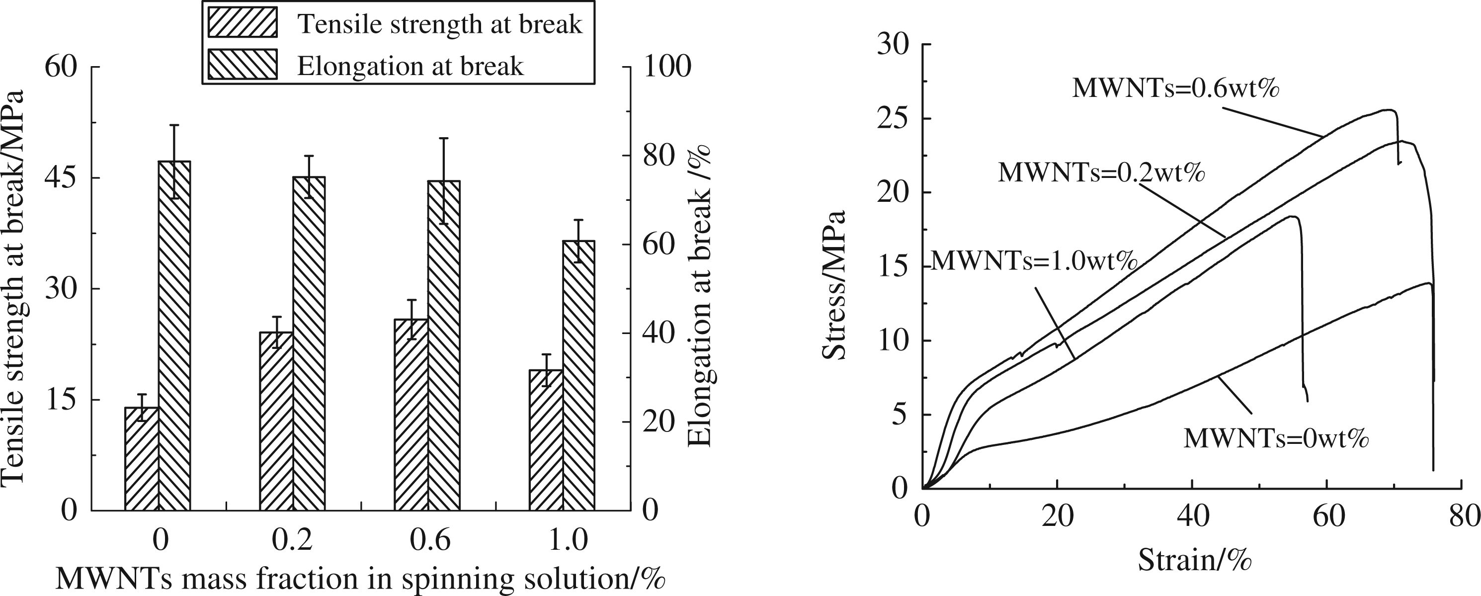
Conclusions
MWNT/PMIA nanofiber mats at different MWNT concentrations were fabricated by electrospinning. The results showed the nanofiber diameter is reduced with the increase of MWNT concentrations while the surfaces of electrospun nanofibers become rough in comparison with that of undosed version. The MWNTs are well dispersed in the nanofibers and well aligned along the nanofibers. The dosing level of MWNTs does not change both the crystalline structure and initial degradation temperature of the nanofibers. Compared with the commercial PMIA fibers, the crystallinity and thermal stability of the nanofibers are decreased. The tensile strengths at the breaking point of the nanofiber mats show significant enhancement by adding MWNTs with the maximum increase of the strength by ca. 86% at a load of 0.6 wt%.
Footnotes
Funding
This work was supported by the Creative Research Project for the Graduate Students of Jiangsu Province (CXZZ11_0104) and also by the Priority Academic Program Development of Jiangsu Higher Education Institutions (PAPD).