



Abstract
Sutures are the materials primarily used for closing wounds, and their performance is significantly dependent on their mechanical characteristics. Thus, their tensile property is a key parameter responsible for the success of a suture. In this paper, a simple analytical tensile model of braided sutures has been developed based on braid geometry, braid kinematics, and constituent monofilament properties. The model has accounted for the changes in the braid geometry, including braid angle, diameter, and Poisson’s ratio. The kinematics of the braided suture is analyzed pertaining to monofilament locking or jamming in the braid. The model of jamming state of monofilaments has been presented, and both braid angle and diameter are found to be critical design parameters. The experimental results have been compared to the theoretical stress–strain curves of braided sutures, and an excellent agreement has been observed between them.
Sutures are the materials primarily used for closing the wounds that are caused by surgery or trauma. They are generally classified as absorbable and nonabsorbable materials based on the fact that the former loses its tensile strength within a defined time scale, whereas the latter is relatively unaffected by biological activities of body tissues.1–3 This classification indicates that the tensile property is a key parameter responsible for the success of a suture. 4 However, the other properties of sutures, including physical characteristics, tissue reaction, knot security, capillarity, and degree of absorption, need to be appropriately selected. Nevertheless, Chu 5 has revealed that the shape of the stress–strain curve of a suture along with the mechanical properties obtained from the curve are significantly important in the wound-healing process. Ideally, the stress–strain behavior of suture should exactly match that of the tissue to be sewed. The stress–strain behavior of the sutures is dependent on their physical characteristics, and accordingly, sutures have been classified as monofilament and multifilament types. 1 Monofilament sutures consist of a single strand of filament, whereas multifilament sutures are made up of several filaments or strands that are generally twisted or braided together. Multifilament braided sutures offer higher tensile strength, pliability, and flexibility in comparison to monofilament sutures. However, the multifilament sutures can produce a higher inflammatory reaction, which can be minimized either by the help of coating or optimizing the braid geometry.6–8
Braiding is generally used for producing narrow rope-like materials by interlacing diagonally three or more strands of filaments or yarns. The bundles of filaments in a braid are interlaced in a similar way to that of the interlacements of ribbons formed in the Maypole dance. This results in a tubular woven structure in which the constituent filaments follow helical paths, simultaneously forming the interlacements between them. The mechanical characteristics of such a structure can be predicted by investigating the synergistic deformation behavior of both twisted yarns and square woven fabrics. Nevertheless, Brunnschweiler 9 carried out a pioneering work on the structural and tensile properties of braided materials. Subsequently, several researchers have formed the relationship between the geometrical and tensile properties of tubular braided materials.10–14 However, the understanding of tensile mechanics of braided materials is still lacking and quite contradictory in the literature.11,12,14 For instance, at higher levels of loading, the braid tends to approach the jammed state such that no movement of constituent filaments or yarns takes place toward the loading direction, and the maximum packing of constituent filaments is attained. This jamming state of filaments in the braided material has been indicated either by the braid (helical) angle becoming constant or when the decrease in the braid diameter is almost negligible.11,12,14 In this research work, a mathematical model of the jamming state of monofilaments will be presented that considers the effect of both braid angle and braid diameter. The main objective of this research work is to predict the stress–strain behavior of braided sutures based on braid geometry, braid kinematics, and constituent monofilament properties. Subsequently, the tensile properties of braided sutures obtained from an analytical model have been validated with experimental work.
1. Theoretical
In general, the following assumptions have been made to predict the braid geometrical parameters, braid kinematics, and tensile properties of braided sutures.
The braided suture is made up of monofilaments, but the present analysis can be extended for braids containing multifilaments as constituent materials. However, appropriate modifications are required in the geometry and tensile mechanics of multifilament braided sutures.
The cross-sectional shape and diameter of monofilaments remains unaffected during the application of a load.
The filament reorientation has been modeled based on the fact that the crossover points deform in an affine manner with the braid continuum and the vectors describing the filament orientations.
The transverse forces between the filaments have been neglected, and the total volume of the braided suture is conserved under tension.
1.1 Key geometrical parameters of braided sutures
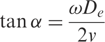
A braided suture consists of two sets of helical filaments or yarns interlacing in opposite directions, and the geometrical parameters of the proposed model are shown in Figure 1. The key design parameters of the braid are diameter of the filament or yarn (d), the inside diameter of the braid (D), the effective braid diameter (De) and the braid or helix angle (α). A flat structure of diamond trellis type is produced by slitting along the braid axis, as shown in Figure 2. A unit cell of trellis is formed by the interlacements of filaments or yarns, and each filament or yarn forms a helical path. Thus, the braid angle (α) is the most important parameter, which is defined as the angle between the filament and braid axes, as shown in Figure 1. These helical filaments or yarns may be assumed to behave as a particle rotating around a circle while traversing along the braid axis. Accordingly, the braid angle (α) has been related to the rotational speed of the carriers (ω) and the take-up speed (v) as shown below.
15
Parametric model of braided suture in (a) cross-sectional view and (b) side view. A trellis unit cell shown inside the regular (2/2) braided suture.
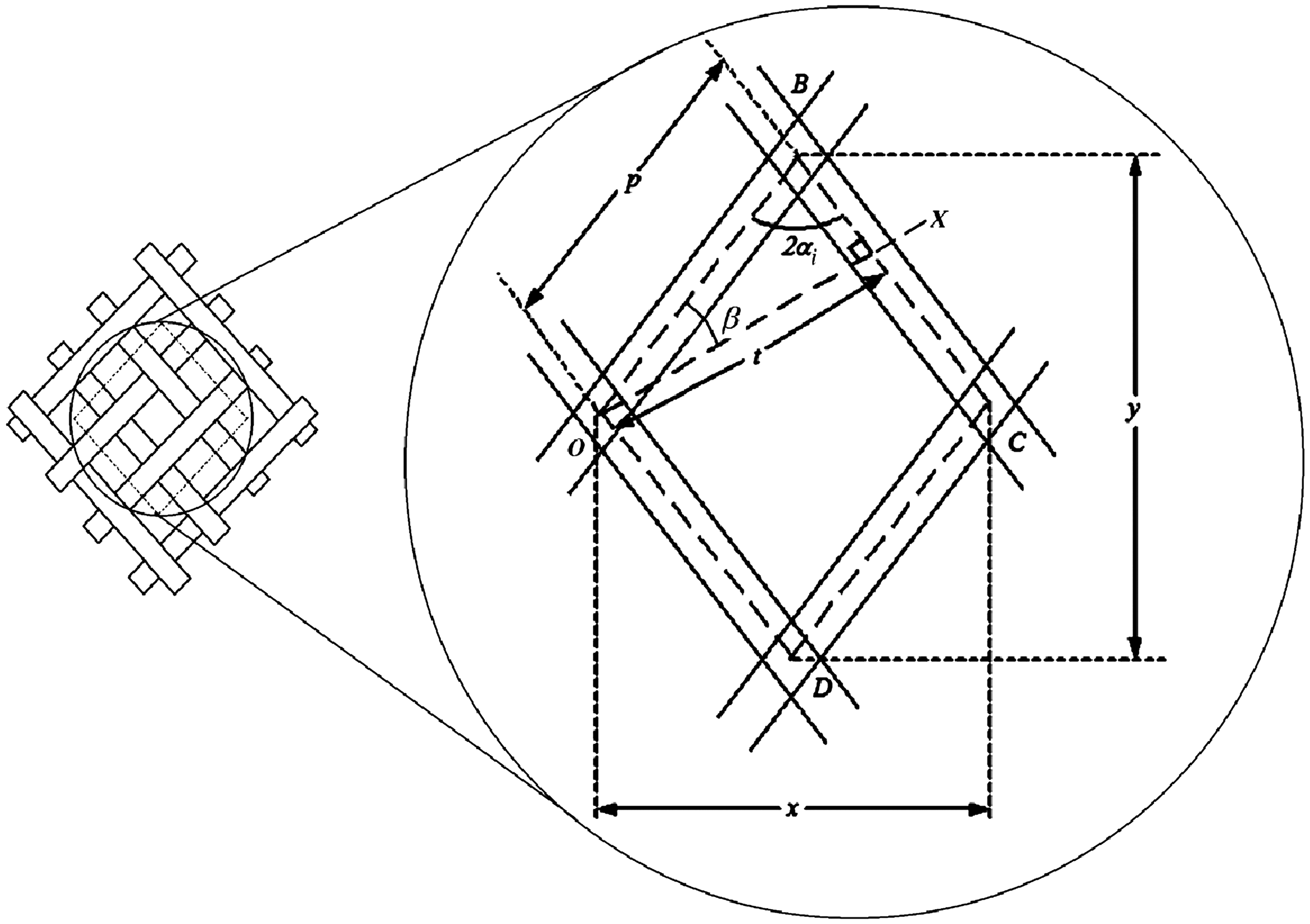

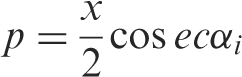
Alternatively, the braid angle can be calculated based on the pitch or length of one diamond trellis units (p), as shown in the following equation (see Figure 2).

1.2 Braid kinematics
Under low-loading conditions, the braids go through the geometric transition, i.e. occurrence of filament reorientation, and the braid angle decreases resulting in an increase in length and decrease in braid diameter, as illustrated in Figure 3. The braid angle continues to decrease until the filaments may become tightly packed and the structure is jammed such that no further movement of filaments can take place. Subsequently, the filament properties govern the tensile response of a braided suture. The filament reorientation can be easily modeled based on the fact that the crossover points deform in an affine manner with the braid continuum and the vectors describing the filament orientations. Consider a monofilament oriented at an initial orientation angle, αi, with respect to the loading direction and is reorientated to αf under uniaxial tensile loading according to equation (4).
16
Therefore
Filament reorientation in a braided suture under low-loading conditions.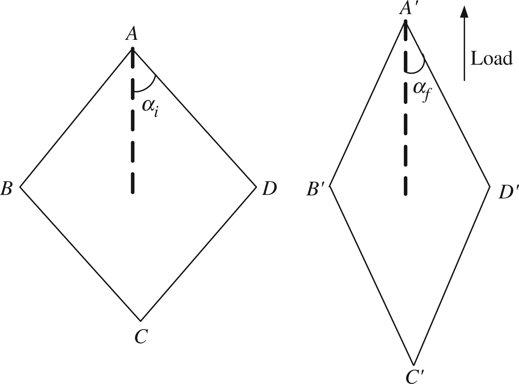

For computing the jamming condition in a braided structure, consider a plane OX normal to the direction of the crossing monofilament axis (BC) as shown in Figure 2. The projection of pitch (p), i.e. the average distance between the consecutive monofilaments in a unit cell (ABCDE), is t on the OX plane. Therefore

Also

Furthermore


The cross-section of monofilaments along the OX direction before and after jamming is shown in Figure 4. The monofilament cross-sections are similar to that of the monofilaments represented in the woven structure when projected on the OX direction.
17
The jamming or locking of structure will lead to minimum possible spaces between the constituent monofilaments, and the new average spacing between the monofilaments after jamming in a unit cell (A′B′C′D′E′) is represented by t′, and accordingly, the braid angle and the braid diameter in the jammed state is defined by α′ and Cross-sectional views of the filaments (a) before (b) after jamming in the braided suture.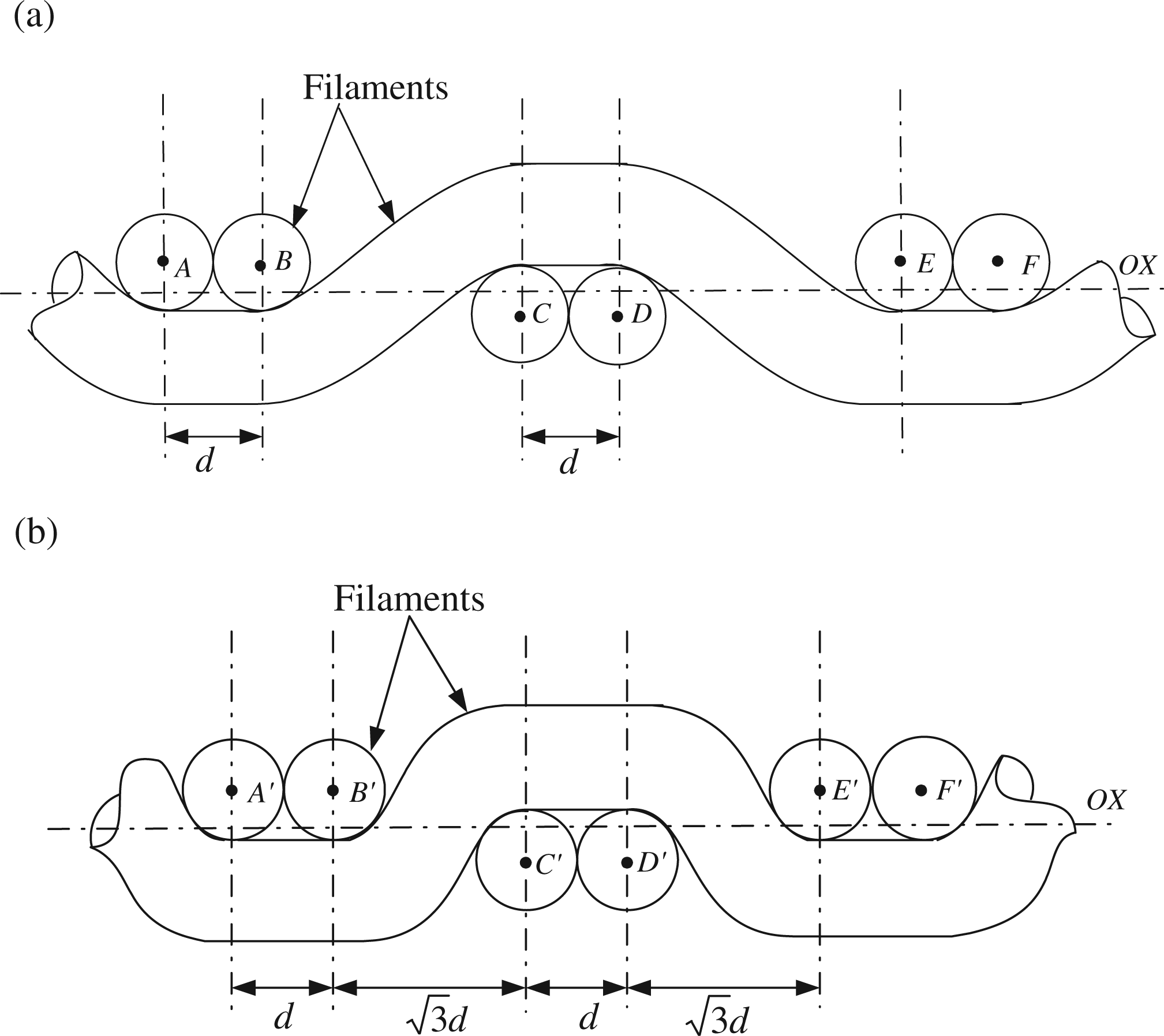
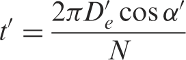
In case of a regular braid (2/2), the minimum average spacing between the monofilaments is given by Peirce.
17


Equation (12) shows the jamming condition of the monofilaments in a braided structure, and it can be clearly seen that both braid diameter and braid angle should approach a critical value to satisfy the jamming condition.
1.3 Tensile mechanics of braided sutures
In this study, braid consists of interlacing monofilaments aligned at a predefined orientation (αi), and in order to calculate the braid stress, the contribution of constituent monofilament stress along with the contribution of the number of monofilaments aligned perpendicular to their axes need to be accounted. This concept is analogous to that of the mechanics of continuous filament yarns, also known as the “fiber obliquity” effect, in which the yarn stress is predicted based on the twist or helical angles of constituent filaments along with their respective stresses.
18
Here, it must be noted that transverse forces between the filaments have been neglected. Therefore
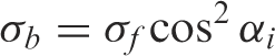
Equation (13) is valid when the braid is 100% covered by the constituent monofilaments, which is not the case in reality.
5
There are some voids present between the constituent monofilaments, and therefore, the fiber-volume fraction needs to be accounted for the above equation.

Furthermore, the fiber-volume fraction has been related to the braid geometrical parameters using the following relationship:
15
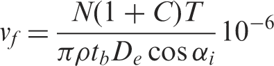
In general, it is also well known that the following constitutive model holds for filament in tension:
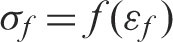
The filament and braid strains have been related with each other.
16

It is important to note the braid stress can be calculated at defined levels of strain by considering the monofilament reorientation based on equation (4). Hence, equations (14) and (15) need to be modified and updated accordingly.


Assuming the total volume of the braided suture is conserved under tension and let εbt and S(εbt) be the true strain and stress, respectively, such that the following relationship is obtained with the engineering stress (σb) and engineering strain (εb).


Thus, the stress–strain relationship of a braided suture can be predicted by combining the equations (4), (16)–(21). In addition, the jamming can be observed in the suture when the equation (12) is satisfied such that the product of cosine of the braid angle and the braid diameter approaches a constant value depending on the level of tensile strain, number of constituent filaments and diameter of each filament.
2. Experimental
Polypropylene monofilaments of diameter 0.2 mm (linear density of 28.55 tex) were braided on a 16 carrier maypole braider to produce a regular (2/2 repeat) braided suture of 1.2 mm diameter. The maypole braider consists of two sets of yarn carriers rotating on a circular track in which half of the carriers rotate in a clockwise direction and the remaining half of the set rotates in a counterclockwise direction. Further details of the traditional maypole braider can be obtained from our previous publication.
15
In this study, the regular braided suture consisting of 16 filaments was produced based on the process conditions defined in Table 1. The braid diameters were measured by acquiring the screenshot images at various levels of strains, and the images were analyzed using the IMAGEJ, a public domain image-processing software. Subsequently, the true Poisson’s ratio values were determined by measuring the changes in the braid diameter with respect to the longitudinal strain based on the methodology given by Alderson et al.
19
Figure 5 illustrates the Poisson’s ratio values of braided sutures at various levels of strains. The crimp in the braided suture was also determined using IMAGEJ software. In addition, the stress–strain behavior of constituent polypropylene filament is illustrated in Figure 6. A third-degree polynomial is fitted to simulate the stress–strain behavior of filament in the braided suture.
Relationship between the true Poisson’s ratio and longitudinal strain in a braided suture. Stress–strain relationship of constituent polypropylene filament in a braided suture. Process parameters for the production of braided suture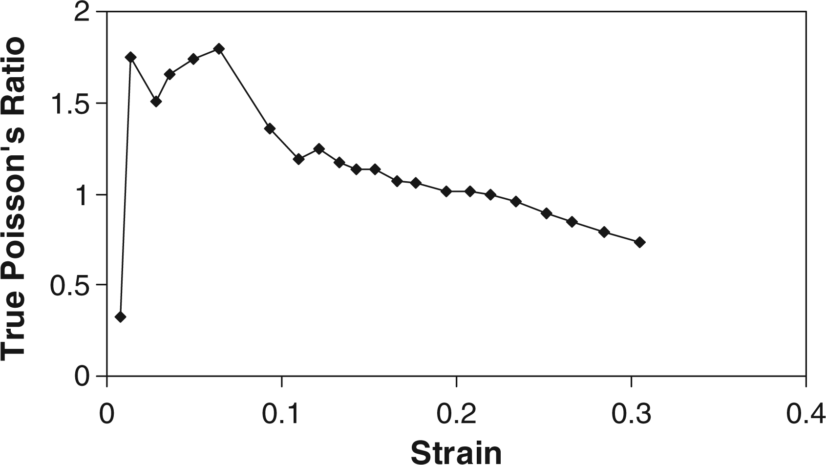


3. Results and discussion
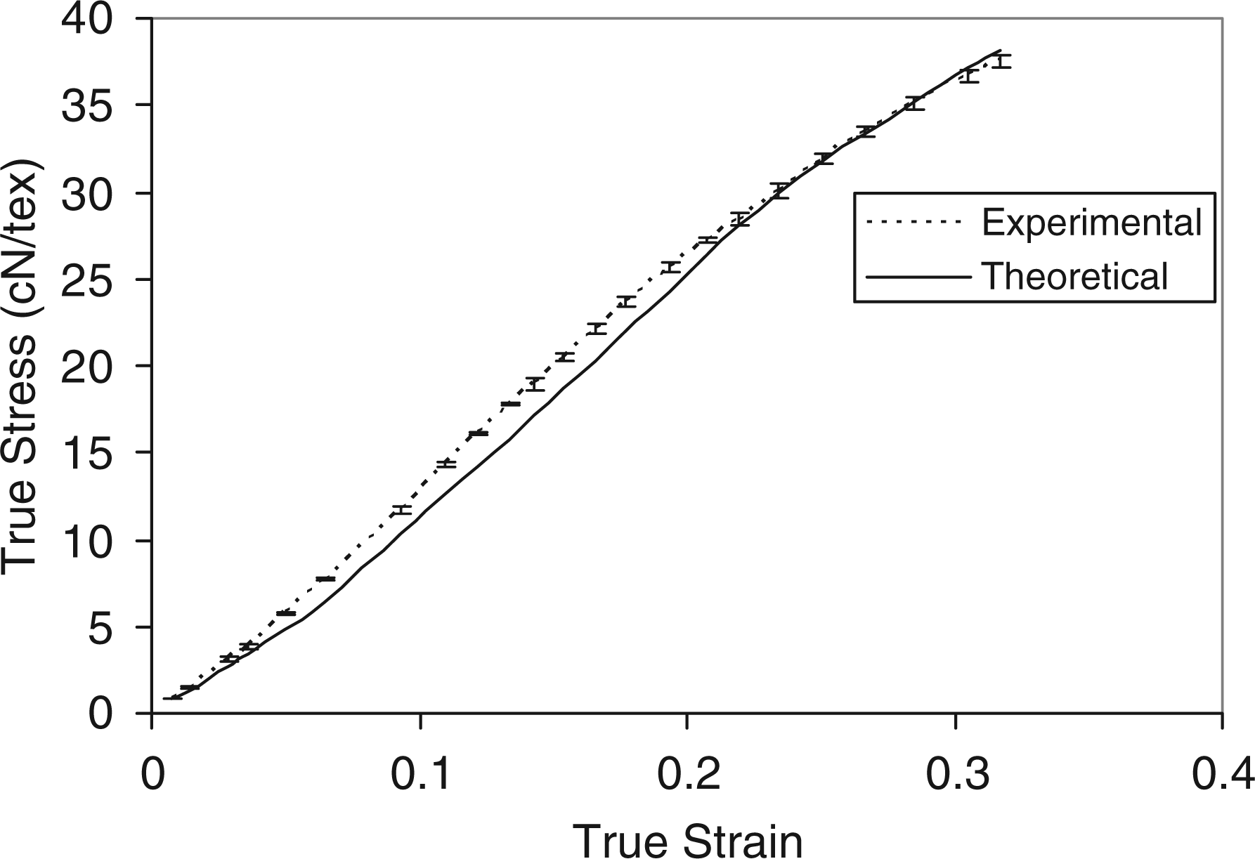
The theoretical braid angle of braided suture is calculated from equation (1) based on the process conditions given in Table 1. The theoretical and experimental braid angles were found to be 22.07 and 20.96°, respectively. Under uniaxial tensile loading, the changes in the braid angles can be calculated using equation (4) based on the determination of Poisson’s ratio at defined levels of strains. It is apparent that the both braid angle and diameter will decrease with an increase in the level of strain. In order to compute the jamming condition for a braided suture consisting of 16 monofilaments that has been fabricated in this study, the value of Relationship between cover factor, fiber volume fraction and true strain in a braided suture. Experimental stress–strain curve of braided suture. Comparison between theoretical and experimental stress–strain curves of braided sutures. Here error bars indicate the standard deviation in five tests.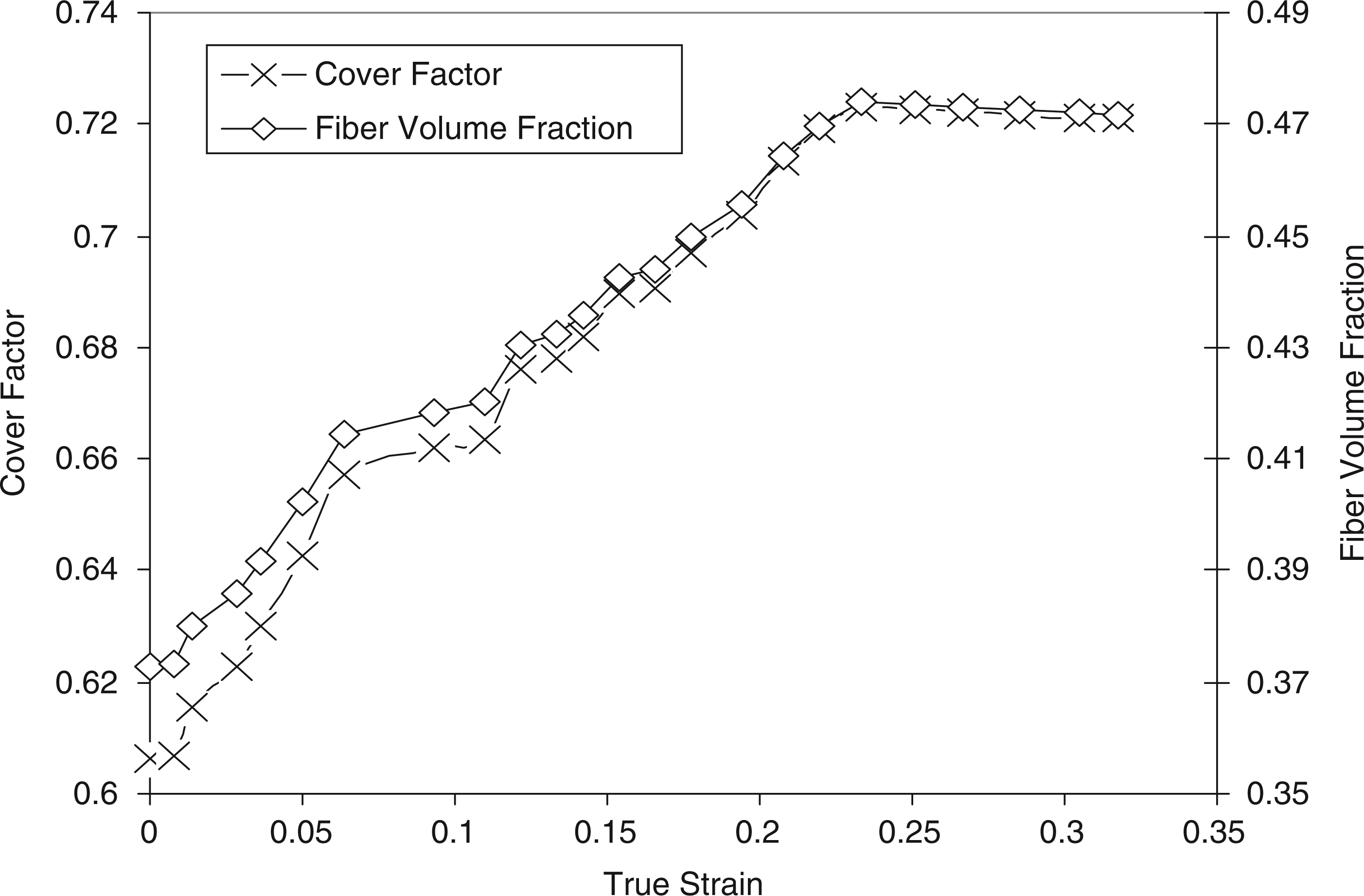

4. Conclusions
The tensile behavior of braided sutures has been investigated based on the braid geometry, braid kinematics, in addition to the resemblance with the yarn, and woven fabric mechanics. A simple tensile model of a braided suture has been proposed by accounting for the changes in the braid geometry, including braid angle, diameter and Poisson’s ratio, along with the constituent monofilament properties. An excellent agreement has been obtained between the theoretical and experimental stress–strain curves of a regular braided suture. In addition, the jamming in the suture, which was previously understood either in terms of constant braid angle or braid diameter at defined level of strain, has been quantified in terms of braid and constituent filament parameters. For braid jamming, both braid angle and diameter should attain a constant value at defined level of strain depending on the type of weave repeat, number of constituent monofilaments and their respective diameters. It has been concluded that the jamming in the regular braided suture investigated in this research work has not been realized. Since the braid angle and diameter did not attain the required constant value (0.69), it did not fulfill the jamming criteria even at the breaking strain level. This is also being confirmed by the cover factor criteria along with a constant decrease in true Poisson’s ratio values even at higher levels of strains. The future work should focus on combining the selection of sets of braid and constituent filament parameters, such as fiber-volume fraction, not only for desirable tensile properties but also for mapping the other suture characteristics, including knot security, capillarity and degree of absorption.
Footnotes
Funding
AR and HS express the gratitude to CSIR, India for financially supporting this research work. The work reported here has been carried out in the scope of the project “Auxetic hybrid circular braids with elastic core for dental floss applications” funded by CSIR, India (Project No. 22(0490)/09/EMR-II).