
Abstract
Ring spun yarn hairiness can be reduced by such methods as spinning with a contact surface and Z-twisting the staple strand in a “left diagonal” yarn path (denoted as LDP). Actually, the LDP method already exists in sirofil spinning technology. In this study, mechanism analysis of controlling and trapping staple fibers is conducted theoretically for sirofil spinning with a contact surface. Analysis reveals that contacting with a rubber surface leads to deformation of the straight sirofil spinning strand; this can better the tension and twist distribution on the right-hand component of the sirofil spinning triangle to improve LDP sirofil yarn appearance. Related experiments are also carried out to validate the theoretical analysis. Online pictorial investigation confirms the deformation of the straight sirofil composite yarn once it contacts with a rubber surface. Experimental results show that the lower weight loss and smoother appearance are bestowed upon LDP sirofil yarn spun with a rubber contact surface, which agrees well with corresponding theoretical analysis.
Since its application in 1832, 1 ring spinning has become one of the most commercially used systems for staple yarn manufacture. During ring spinning, twist is generated in the balloon zone, and it transfers upward to the yarn formation zone. 2 During the twist transformation, the yarn twist density will be weakened due to the twist blockage by the angle of yarn wrapping at the yarn guider. 3 Meanwhile, fiber strand delivered from the front roller nip is ribbon-like during practical conventional ring spinning. Therefore, a spinning triangle zone occurs in front of the front roller nip. Unfortunately, this spinning triangle zone is not only the weakest area, but also the most awkward in fiber controlling; this leads to frequent end-breakage and imperfect yarn qualities, such as hairy appearance and uneven linear mass distribution.
In order to improve ring spinning performance and resultant yarn quality, various novel ring staple spinning methods have been developed mainly on the basis of staple spinning strand control enhancements. Siro-spinning improves the staple fiber control during ring spinning by feeding two separated parallel rovings into the ring frame drawing system.4,5 Siro-spinning has been proved to be an effective method to manufacture yarn with a smoother surface, 6 higher strength 7 and better frictional properties 8 than the corresponding conventional ring spinning. Another effective way to depress poor control of the outmost periphery fibers of a large spinning triangle is condensing the staple strand in the main drafting zone to eliminate the spinning triangle;9–11 thus, this method is called condensed or compact spinning. Previous studies show that compact yarns are smoother, stronger and more even than the conventional ring spun ones.12–14 Jet-Ring 15 and Air-Suction 16 spinning technologies reduce yarn hairiness by pneumatically re-wrapping protruding fiber ends onto the yarn stem. Nu-torque spinning produces strong yarns with low hairiness and low residual torque by using a false twister in the spinning zone.17–20 Overall, novel ring spinning methods are developed mainly by means of separating single strands into two or several sub-strands, concentrating the triangular ring spinning strand, re-wrapping protruding fiber ends and improving online twisting density distribution. 21
Besides the aforementioned novel methods, another simple and energy-saving method is also employed to control protruding hairs by setting a contact surface in the yarn formation zone.22,23 Such resultant plied yarn properties as hairiness, tenacity and unevenness for contact surface used during ring plying are improved. 22 However, except yarn hairiness, single yarn unevenness and tenacity become deteriorated when the contact surface is applied for single staple ring spinning. 23 In addition, end-breakage is frequent during single staple yarn spinning with a contact surface, which can block some twists to transfer onto a strand in the spinning triangle. With the aim to further investigate the mechanism and expand the application of spinning with a contact surface, this study introduces multifilaments to depress end-breakage of yarn (i.e., sirofil spinning with a contact surface). The combination of the contact surface with sirofil spinning will produce dramatic controlling and trapping of fibers to change yarn appearance. Therefore, this study emphasizes the influence of a contact surface on sirofil yarn appearance by analyzing fiber control and the trapping mechanism in theory. Related experiments are also conducted to validate the theoretical analysis. In specific, count variation and appearance properties are studied for different sirofil spun yarns in this paper.
Theoretical considerations
Effect of the spinning strand path on yarn hairiness
Previous studies show that ring spun yarn hairiness can be reduced by Z-twisting the staple fiber strand with a “left diagonal” yarn path (denoted as LDP).24,25 Disappointingly, this LDP method fails in a widely industrial application for single staple yarn spinning, which might be due to its operation inconvenience. Actually, the LDP method already exists in sirofil spinning technology.
Sirofil spinning grew out of siro-spinning via replacing one siro-component with strong multifilaments to strengthen the spun yarn,
26
which is illustrated in Figure 1. When the left siro component is substituted by multifilaments, the staple strand on the right is twisting just in a “left diagonal” path, shown in Figure 1(a). On the contrary, if the right siro component is substituted by multifilaments, the staple strand on the left is twisting just in a “right diagonal” path (denoted as RDP), shown in Figure 1(b). According to previous studies,24,25 the LDP method can reduce yarn hairiness due to the left-hand side fiber control improvement by shortening the distance between the front nip and convergence point, while the right-hand side fibers are still under control via pre-Z-twisting; the RDP method deteriorates yarn hairiness due to further reduced control of fibers on the left-hand side of the Z-twisting triangle. Luckily, the sirofil spinning shown in Figure 1(a) is supposed to include an LDP method in the yarn formation zone, which can be called LDP sirofil spinning. Besides the above known factors, other hidden mechanisms await to be disclosed to support the LDP sirofil yarn as smoother than the RDP sirofil one under the same spinning condition.
Illustration of sirofil spinning: (a) spinning with filaments on the left and the staple strand on the right; (b) sirofil spinning with the staple strand on the left and filaments on the right.
Effect of a contact surface on the sirofil spinning strand configuration
Sirofil spun yarn is still hairy, which is probably because the spinning strand hairiness in the “open arm” configuration will not be well trapped at the convergence point during the ring twisting.
22
In order to improve sirofil yarn appearance, a rubber surface is applied to contact the sirofil composite spinning strand, which is illustrated in Figure 2(b).
Illustration of sirofil spinning with a contact surface: (a) sirofil spinning without a contact surface; (b) sirofil spinning with a contact surface.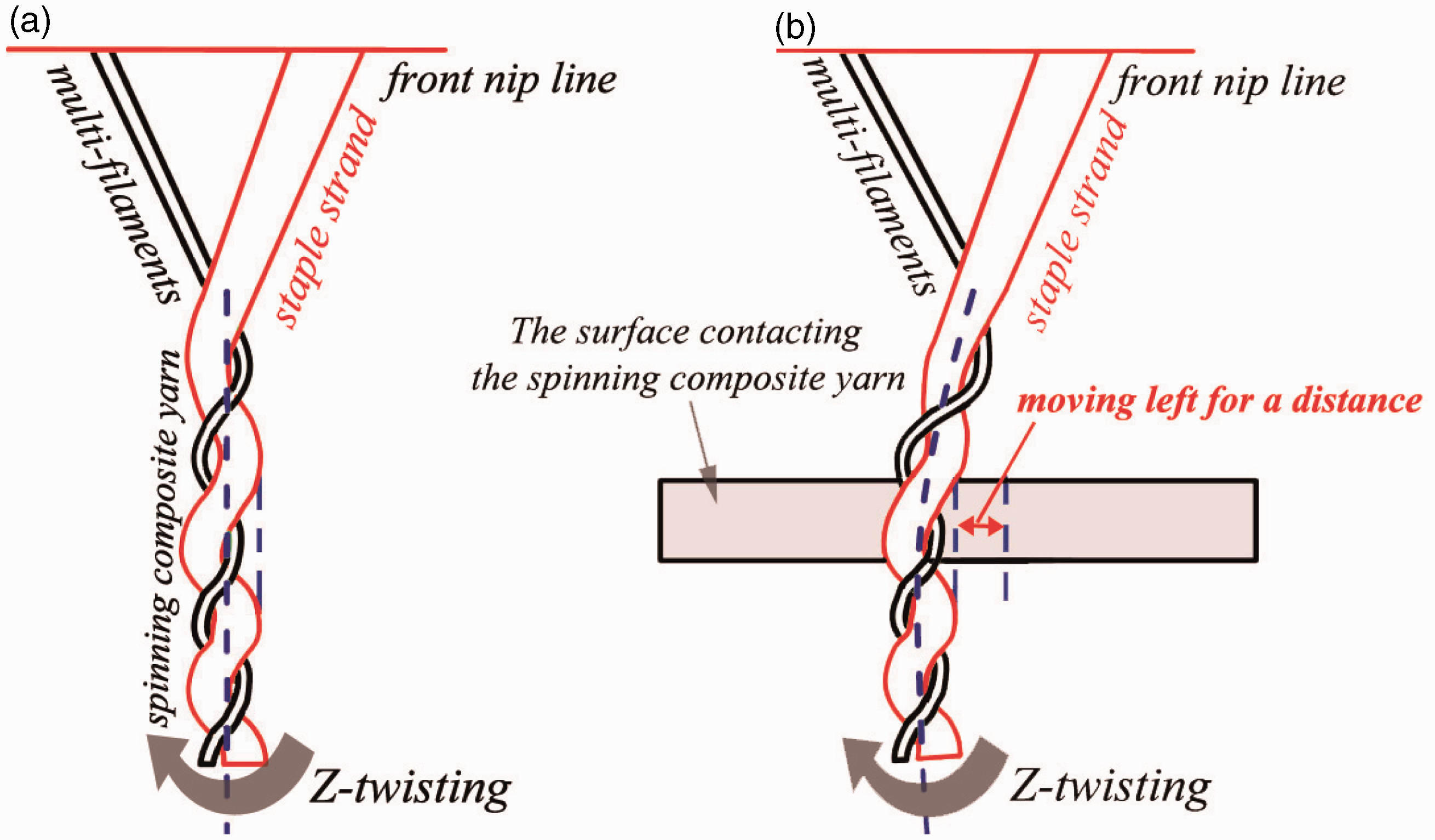
Our previous study shows that protruding hairs can be reduced during the yarn rolling on the contact surface, 23 which is mainly because many nip points are created to hold the hairs to re-wrap onto the yarn stem. 27 Actually, the motion between yarn hair and the contact surface is regarded as sliding friction, while the yarn stem rolling on the surface is regarded as rolling friction. Nearly all frictions between hairs and the contact surface are created on the left-hand side of the yarn stem for a Z-twisting strand. This is attributed to the hair suffering pressure force only in the left-hand side during the Z-twisting strand rolling on the surface. Therefore, once the straight spinning composite yarn (shown in Figure 2(a)) contacts with a surface, it will deform as rolling on the contact surface pushes the yarn stem to the left for a distance, which is illustrated in Figure 2(b). To investigate the influence of deformation on sirofil spun performances, the mechanical analysis is conducted below.
Mechanical analysis of sirofil spinning strand configuration affecting sirofil yarn formation with and without a contact surface
The force balance of sirofil spinning with a contact surface is shown in Figure 3(b), where
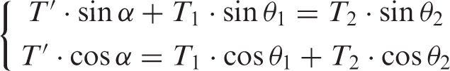
According to the force balance in the O′ area, Equations (5)–(7) can be derived:
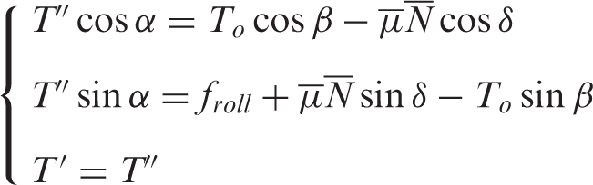
During the spinning, the contact surface is near to convergence point O and far from the pigtail guider; therefore, angle β is small enough to be omitted. Then, Equations (5)–(7) can be transformed as below:
Illustration of mechanical analysis of the sirofil yarn formation zone: (a) sirofil spinning without a contact surface; (b) sirofil spinning with a contact surface.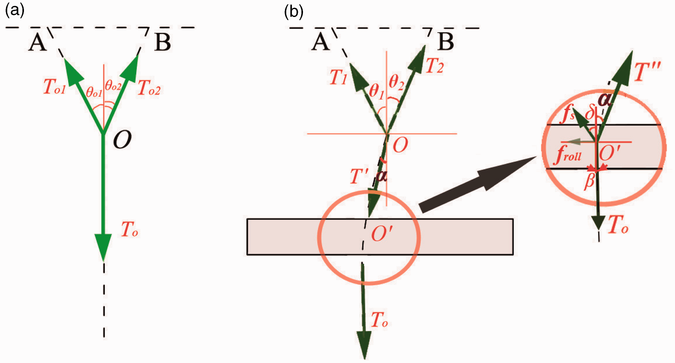

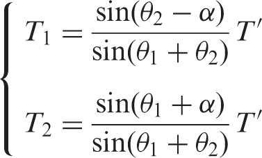
Solving Equations (8)–(10), we can get the result below:
With a combination of Equations (3), (4) and (11), we can get the equations below:
CASE I
If
If the linear densities of multifilament and staple strand are the same, we can get
CASE II
If
Previous study shows that torque is proportional to tension on each of the two strands, and the twist is proportional to torque; 28 this indicates that the higher the tension on the strand, the more twists are distributing on the strand. Therefore, Inequation (17) suggests that the right-hand component has higher twisting density than the left-hand component for the sirofil yarn formation zone during a Z-twisting process. Under this situation, the staple strand located on the right (Figure 1(a)) is under better fiber control as more twists are inserted. Meanwhile, the left multifilament gets a looser structure due to lower twist density distribution, which benefits the binding of the staple fiber ends into the resultant sirofil yarn stem by filament wrapping the staple strand in a larger interfacial contact surface during spinning.
CASE III
If

In this case, only the right-hand component has inserted twists. Thus, the staple fiber strand should not be arranged on the left-hand side, or else it would suffer severe fiber loss. In particular, the left-hand component is just wrapping on the right-hand component in this condition. Therefore, if the right-hand component is the staple strand (Figure 1(a)), the produced sirofil yarn could be smooth as the pre-twisted staple strand is effectively wrapped by multifilament. On the contrary, if the left-hand component is the staple strand (Figure 1(b)), the produced sirofil yarn could be hairy. The first reason for this is that, firstly, the non-pre-twisted staple strand is apt to generate irregular fiber loss during spinning; secondly, the staple fibers wrapping on the pre-twisted multifilament contribute more protruding fiber ends.
Effect of a rubber contact surface on yarn appearance properties
According to our previous studies,22,23 the larger the friction of the rubber contact surface between the yarn stem, the more hairs would be wrapped onto the yarn stem to smooth the yarn surface. However, a higher friction force between a rubber contact surface and yarn stem will block more twists to transfer onto sirofil components before convergence, which may deteriorate fiber trapping of the sub-strand from the front nip; deteriorated fiber trapping can increase yarn imperfections by varying fiber loss in the yarn lengthwise. Smoothing the yarn surface and increasing yarn imperfections are combined to influence the resultant yarn appearance properties.
Furthermore, according to the aforementioned analysis, the straight sirofil composite strand stem moves left once it is contact with a rubber surface during the Z-twisting process; consequently, the sirofil yarn formation zone deformation occurs to change the tension and twist distribution on each component in the sirofil spinning triangle. Under the same twist blockage of a rubber surface, LDP sirofil yarn has a smoother surface than RDP sirofil yarn because the staple strand located on the right-hand side (LDP) has a better fiber control than that located on the left-hand side (RDP). To validate the above theoretical analysis, sirofil spinning with and without a rubber contact surface has been conducted in a textile mill, the results of which will be introduced below.
Experimental details
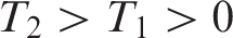
For invalidation, sirofil composite spinning methods with the staple strand located on the right-hand side (e.g., LDP shown in Figure 4(b)) as well as that located on the left-hand side (e.g., LDP shown in Figure 4(c)) are respectively conducted with and without a rubber contact surface on a FA 502 type ring frame in the Jihua 3542 Textile mill (Figure 4(a)). All the spacings of the staple strand and multifilaments remain at 5 mm. The distance is about 15 mm from the contact surface upper edge to the front nip; the length of yarn contacting with the surface is about 5 mm. One spindle is used to produce sirofil composite yarns with and without contact apparatus. One hundred percent combed cotton roving and nylon multifilaments are used to produce each sirofil composite yarn with the same spinning settings: combed cotton roving 520 tex (dry weight, i.e., moisture regain is zero), nylon multifilaments 200 denier/72 fibers, opening of the pressure bar spacer 3.0 mm, spindle speed 14,403.3 rpm, front roller speed 13 m/min, ring type PG1-4254, traveler type 6903 14/0, English twist factor 6.93 and total mechanical draft ratio 40.22; the desired yarn count 36.72 tex.
Sirofil composite spinning methods. (a) panoramic image of sirofil spinning (b) sirofil spinning with the staple strand located in the right side (denoted as LDP sirofil spinning); (c) sirofil spinning with the staple strand located in the left side (denoted as RDP sirofil spinning); LDP means Z-twisting staple strand component in a “left diagonal” path, RDP means Z-twisting staple strand component in a “right diagonal” path.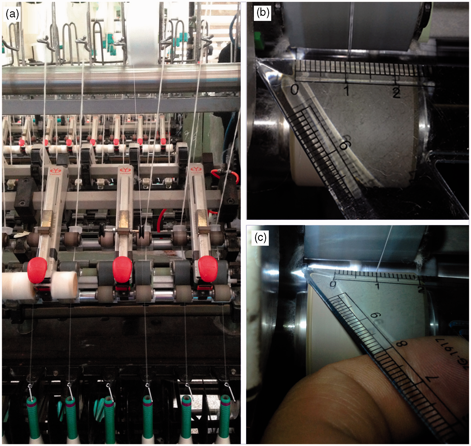
Sirofil composite yarns spun with or without contact apparatus are conditioned for at least 24 hours in the standard laboratory of the Juhua 3542 Textile Company (20 ± 2% relative humidity (RH) and 65 ± 2℃). Then, different yarn samples are weighted per 100 m on an AUY120 electrical balance after measuring using a YG086 Lea's Length Tester; the length of each yarn tested is 300 m and the results are averaged. According to CN GB/T 3292.1-2008 capacitance testing standard, the YG136 capacitive evenness tester is used to test yarn unevenness; the testing speed is 400 m/min, and the testing length for each samples is 400 m. After firstly 4 hours’ steam treatment and then 5 hours hot air drying, composite yarn hairiness index is tested using a YG171B-2 hairiness meter according to the CN textile industry standard FZ/T 01086-2000, which is widely used in Chinese textile mills; the test speed is 30 m/min, test segment length is 10 m, and 10 successive segments are tested for each composite yarn sample. All of the above tests are conducted under the standard condition.
Results and analysis
Effect of a rubber contact surface on sirofil yarn formation zone configuration
Figure 5 shows the images of the sirofil yarn formation zone with and without a rubber contact surface. During the sirofil spinning without the rubber contact surface, fibers at the outmost of the staple strand fail to be twisted into the yarn body to form a losing fiber flow, which can be seen in Figures 5(b) and (c). In addition, the main body of the desired straight composted spinning strand section presents dimensional position vibration due to the existence of yarn bloom. For the yarn formation zone of the sirofil composite spinning with the rubber contact surface, the desired straight sirofil spinning strand deforms via moving to the left on the contact surface, which can be seen in Figure 5(a). This phenomenon is consistent with the aforementioned theoretical deformation prediction. After a comparison of Figures 5(b) and (c) with Figures 5(d) and (e), it can be seen that the sirofil composite stem near to the front nip is more stable for spinning with the rubber contact surface than that for spinning without the rubber contact surface. Vibration of the sirofil yarn main body is also alleviated as the spinning bloom decreases after an introduction of a rubber contact surface.
Pictorial analysis of sirofil yarn formation zone. (a) sirofil spinning composite strand deformation with a rubber contact surface; (b) LDP sirofil spinning without a rubber contact surface; (c) RDP sirofil spinning without a rubber contact surface; (d) LDP sirofil spinning with a rubber contact surface; (e) RDP sirofil spinning with a rubber contact surface; LDP means Z-twisting staple strand component in a “left diagonal” path, RDP means Z-twisting staple strand component in a “right diagonal” path.
Effect of a rubber contact surface on fiber loss during sirofil spinning
Comparisons of different sirofil spun yarn counts
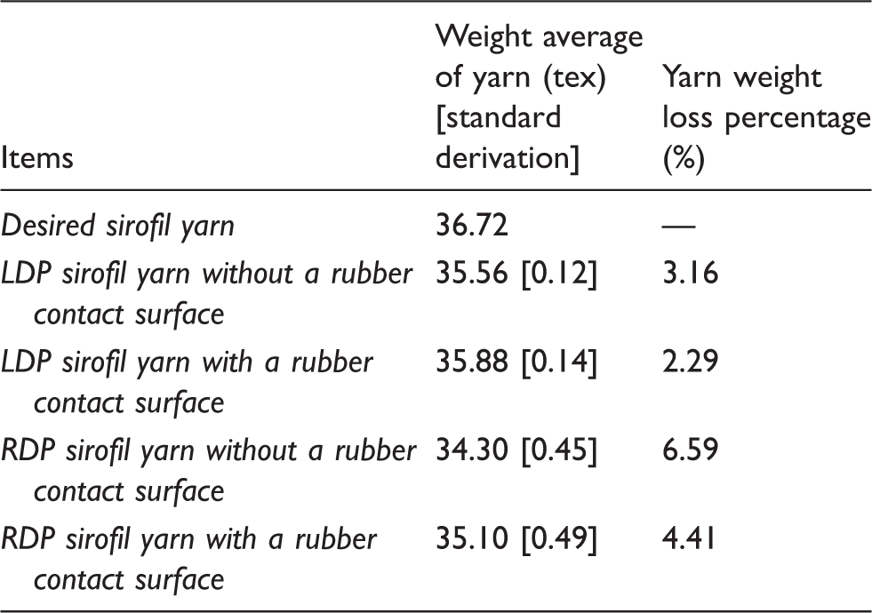
Statistical analysis (Appendix I) indicated that weight of RDP sirofil yarn without a rubber contact surface is statistically lower than that of other sirofil yarn samples. This is ascribed to the poor control of staple fibers for RDP sirofil yarn spinning without a contact surface. Once applying a rubber surface to the contact sirofil spinning strand, yarn hairs and even some lost fibers (see Figure 5) can be re-wrapped onto the yarn stem. Therefore, yarn weight loss percentage lowers after applying a rubber contact surface for both LDP and RDP sirofil spinning.
Effect of a rubber contact surface on yarn hairiness
An IXUS 75 type Canon digital camera was applied to take an original image of sirofil spinning with a rubber contact surface, shown in Figure 6(a). For clear observation of the online spun yarn appearance, Photoshop software was used to treat the sirofil yarn appearance image according to Cybulska’s method, which includes three sequential steps: yarn image segmentation; segmentation correction to determine the edge of the yarn core; and yarn hairiness estimation at any point of yarn length.
30
The treated image is provided in Figure 6(b). It obviously shows that the sirofil yarn (red section) within the rubber contact surface front edge and convergence point is much more hairy than that delivered downward from the contact surface (green section).
Online comparison of sirofil composite spun yarn hairiness before and after the rubber contact surface: (a) original yarn appearance image; (b) treated yarn appearance image.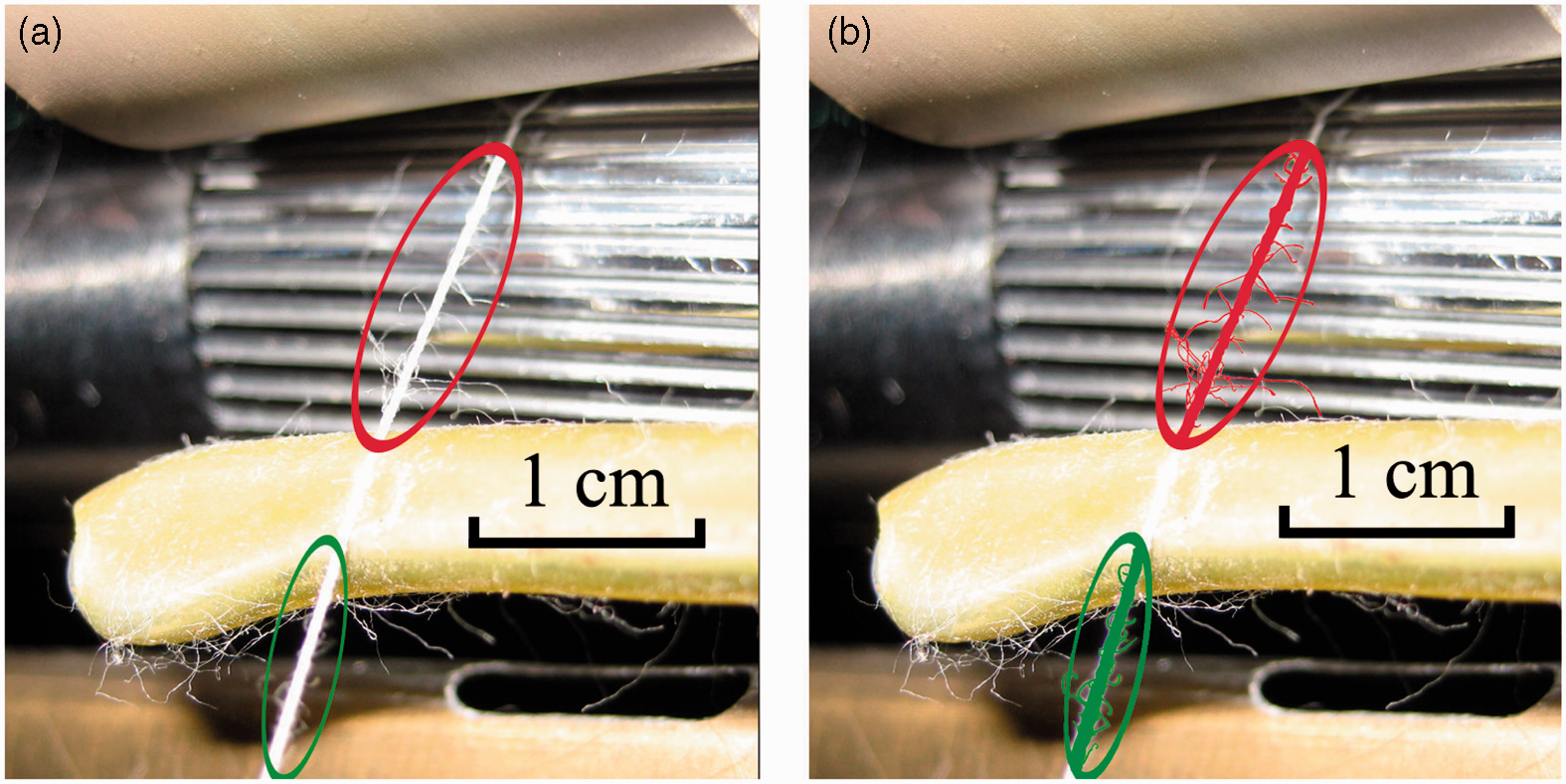
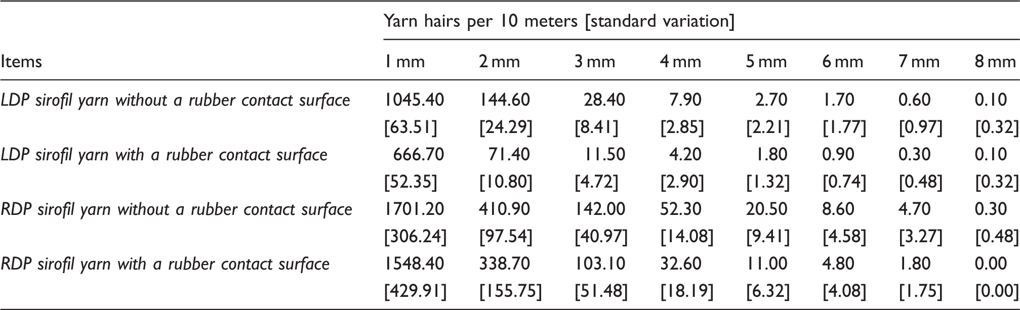
Hairiness of sirofil composite yarns spun with and without a rubber contact surface
To investigate specific yarn hairiness reduction by the rubber contact surface, hairiness eliminating percentage (shown in Figure 7) is calculated according to the following equation:
29
Hairiness eliminating percentage comparison for LDP and RDP sirofil yarns after applying the rubber contact surface during spinning; LDP means Z-twisting staple strand component in a “left diagonal” path, RDP means Z-twisting staple strand component in a “right diagonal” path.
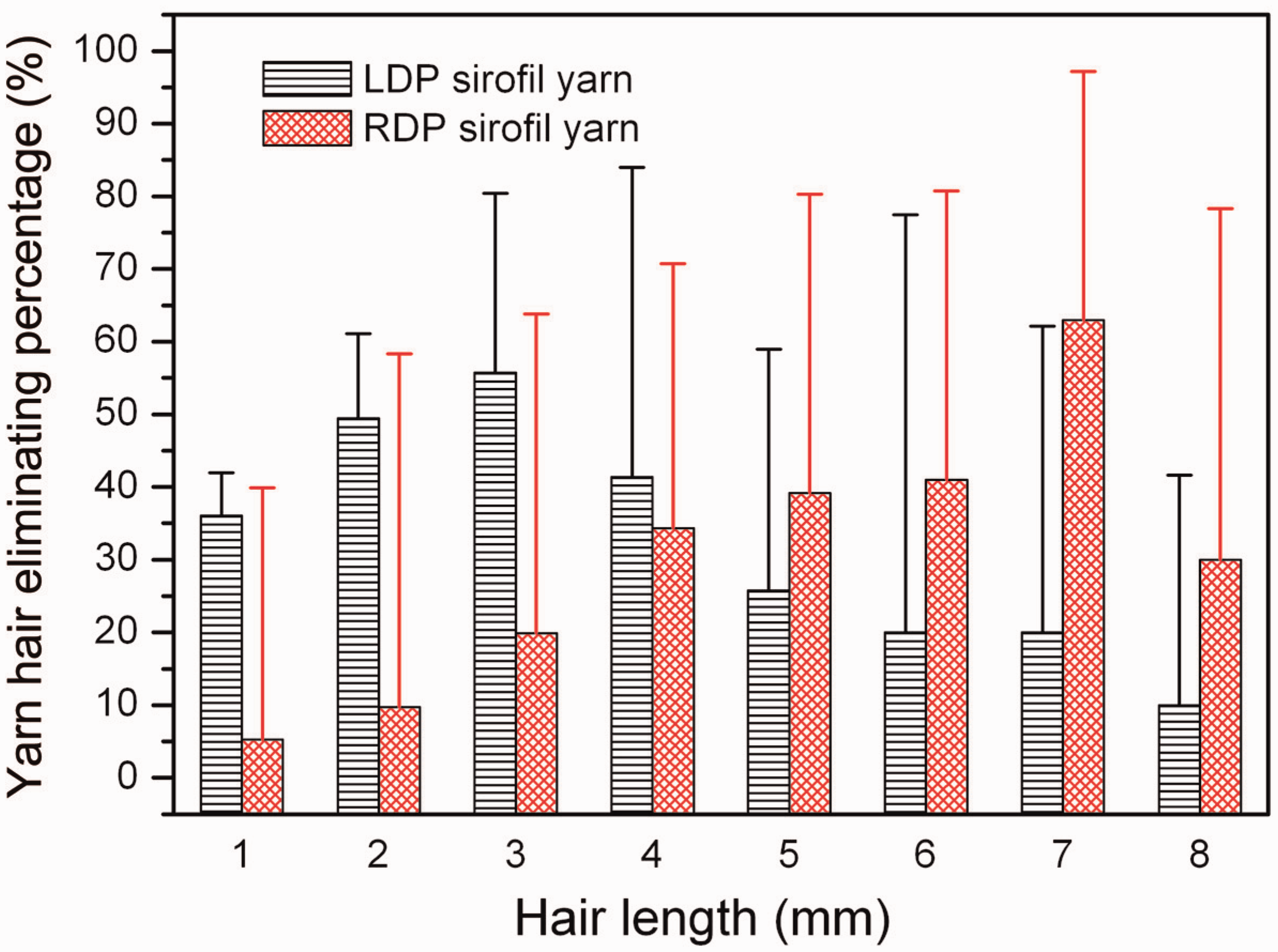
Figure 7 shows that hairiness eliminating percentage increases firstly and then decreases as the hair length increases for both LDP and RDP sirofil yarns; LDP sirofil spinning with a contact surface is better to decrease short hairs, while RDP sirofil spinning with a contact surface is better to decrease long hairs. Specifically, the eliminating percentage is low for hairs shorter than 4 mm and high for hairs longer than 4 mm for LDP, and vice versa for RDP. This may be because the LDP sirofil system pre-twists and traps the staple strand more easily to yield smoother yarn than the RDP sirofil system. LDP sirofil yarns are so smooth that there are not enough long hairs for the rubber contact surface to reduce. In addition, the limit of bars in Figure 7 may be due to high variation caused by the rubber surface.
Effect of a rubber contact surface on sirofil spun yarn irregularity
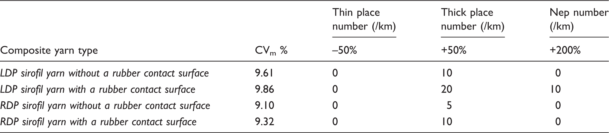
Appearance parameters of sirofil yarns spun with and without a rubber contact surface
Conclusions
Theoretical and practical studies have been done to investigate the influence of a surface-contacting spinning strand on sirofil yarn appearance. Firstly, the fiber controlling and trapping mechanism is theoretically analyzed for sirofil spinning with a contact surface. Theoretical analysis reveals that once the straight spinning composite Z-twist yarn contacts with a surface, it will deform by rolling to the left for a distance on the rubber contact surface. Consequently, the deformation changes the tension and twist distribution on each component in the sirofil spinning triangle according to mechanical analysis. In detail, under the same twist blockage of a rubber surface, the staple strand located on the right-hand side has a better fiber control than that located on the left-hand side. Secondly, related experiments are also conducted to validate the theoretical analysis. Online pictorial investigation confirms that the straight spinning composite yarn deforms after contacting with a rubber surface. Moreover, the sirofil composite stem near to the front nip is more stable for spinning with a rubber contact surface than that for spinning without a rubber contact surface. Quantitative comparative results indicate that total hair amount of LDP sirofil yarn is statistically lower than that of RDP. In particular, total hair reduction of LDP sirofil yarn is larger than that of RDP sirofil yarn via spinning with a rubber contact surface, which agrees well with the aforementioned theoretical analysis. Under the same spinning condition, unevenness CV% and imperfections of RDP sirofil yarn are better than that of LDP sirofil yarn, which might be because the larger fiber loss during RDP sirofil spinning highlights the even multifilament content in the resultant composite yarn structure.
More related experimental studies will be reported later concerning the influence of such contact parameters as rubber dimensions and contact angle on yarn properties, including tensile properties.
Footnotes
Funding
This research was supported by the Major State Basic Research Development Program (973 Program; project no. 2012CB722701).