
Abstract
This work presents fabrication of purely ceramic submicron fibers by rotary jet-spinning – a recently developed method. An inertial force is used to form fibrous jets made of viscous dispersions, which then solidify during solvent evaporation. Precursor suspensions were prepared with the use of water as the only solvent, non-toxic Fe2O3 ceramic powder and poly(ethylene oxide) – a fiber-forming agent. The obtained fibers were in the range of 0.2–1.4 µm in diameter. This work presents a concept that utilizes ceramic fibers that could potentially be used for arsenic removal based on adsorption-enhanced filtration. We prove that ceramic fibers can be formed by simply adding non-agglomerated particles to a polymer solution. The nonwoven fiber-based approach will allow higher flow rates of the filtrate during purification and enable heat treatment for cleaning the filters. However, by changing the type of particles and/or preparing a mixture of them, the application range of the final product can be significantly broadened.
In recent years fibrous materials have drawn much attention,1–3 because of their versatile properties and numerous applications. They are used in a wide range of areas, such as filtration, catalysis, construction, automotive and agriculture. Fibrous materials provide a high surface to volume ratio. This feature makes them an excellent base material for adsorption applications where a large contact area between adsorbing and the media to be adsorbed is of high importance. A wide application range causes an increasing interest in the development and improvement of methods 4 for fiber production. Nowadays, commonly used methods are electrospinning5,6 and melt blowing.7–10 Both techniques enable one to obtain high-quality polymeric fibers. However, the methods have many limitations and the cost associated with the production is still relatively high. In electrospinning fibers are spun resulting from an electrostatic interaction between the electrically charged jet of the fiber precursor and the oppositely charged collector system. To induce an electrical field in precursors either solvents, which are often toxic, or conductivity increasing additives are essential. Unlike electrospinning, melt blowing does not require any toxic solvents. Nevertheless, high-velocity air of increased temperature (mostly the temperature of a melt) is crucial to form fibers, significantly increasing production costs. Recently, rotary jet-spinning (RJS) seems to be a new alternative for fiber production.
This method uses centrifugal force to form fibers; hence, neither expensive equipment nor toxic solvents are required (which are often needed in electrospinning in order to increase the conductivity of the spun precursors).
Rotary jet-spinning
This spinning technique was presented by Badrossamay et al. 11 in 2010. It was used to produce polymer fibers from polymer–solvent solution with a diameter ranging from 50 to 3500 nm made of poly(lactic acid) (PLA), poly(ethylene oxide) (PEO), poly(acrylic acid), gelatin, an emulsion of gelatin in PLA and PEO doped with fluorescent spherical beads. This method was further explored by Huttunen and Kellomaki. 12 A standard cotton-candy machine was used to produce submicron fibers from polymer melts. This heat-aided RJS technique was utilized to fabricate PLA fibrous floss with a fiber diameter ranging from 1 µm to 10–50 µm. In this method, deposited material, either in the form of a solution/suspension or a molten polymer powder, is placed in a reservoir with two side wall orifices. When the spinneret starts to rotate at speeds larger than a threshold of the balance between capillary and centrifugal forces, a flow of precursor through an orifice initiates. The fibers start to form as soon as the liquid leaves the reservoir. Centrifugal force and aerodynamics elongate the jets, resulting in lowering their diameter due to plastic deformation, whereas the high viscosity of the precursor prevents the jets from breaking into droplets. Solvent evaporation leads to solidification of the fibers before they reach the collection system. Next, dry fibers are collected on polypropylene sticks (collection system) located around the spinneret in a distance of 20 cm.
Recently, Forcespinning™, 13 a method similar to RJS, was developed at the University of Texas. This method was previously used to produce fibers consisting of PEO, 13 Nylon 6, polyvinylidene fluoride, polypropylene, 14 conjugated poly(2,5-bis(2’-ethyl-hexyl)-1,4-phenylenevinylene) and PEO 15 and tin-doped indium oxide, 16 which were the only fabricated ceramic fibers. The tin-doped indium oxide fibers were produced from salt (hydrated chlorides) precursors, which transform into ceramics by chemical decomposition. Mahapatra et al. 17 produced iron oxide/aluminum oxide fibers also with the sol-gel method using electrospinning. We present a nanoparticle-based and environmentally friendly approach to obtain purely ceramic fibers.
Several studies demonstrated successful formation of fibers by other spinning techniques using centrifugal forces. Lu et al. 18 obtained polyacrylonitrile fibers in the nano range by centrifugal spinning, while Chang et al. 19 combined electrospinning and forcespinning in order to obtain polycarbonate, PLA and polyacrylonitrile nanofibers with superior physical properties. Fiber mats composed of natural and synthetic polymers with different molecular masses and polydispersity degrees as well as polyurethane and poly(vinyl chloride) were produced by Mindru et al. 20 with the use of air flow RJS. Sebe et al. 21 fabricated poly(vinylpyrrolidone)/(poly(vinylpyrrolidone-vinylacetate)/iodine fibers with antimicrobial properties by high-speed rotary spinning.
In this work, the fibers were produced by RJS from stabilized nanoparticle dispersions containing polymer as a fiber-forming agent. Heat treatment following the fibers' production removes an organic additive to form purely ceramic material.
Experimental details
All “percent” values in this article represent mass percents relative to the mass of the suspensions if not stated otherwise. All materials were used as-received without further purification.
Fabrication of fibers by RJS requires a viscous medium to form continuous jets of liquid, which will solidify and preserve their shape during the spinning. In this work PEO (Mv = 1,000,000; Sigma Aldrich) was used as a fiber-forming agent. This material is known for its non-toxicity and biocompatible properties. It is also soluble in water and thus allows one to avoid the use of hazardous solvents.
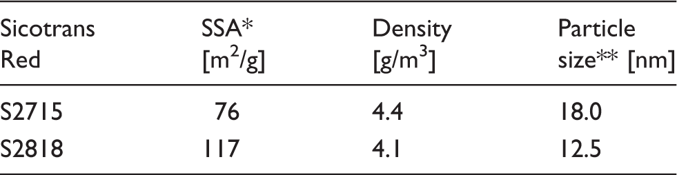
Properties of the used iron oxide powders; *specific surface area measured with the Brunauer–Emmett–Teller (BET) method; **calculated from BET
The fibers were fabricated from an aqueous and thus environmentally friendly precursor. Firstly, 9.0 g of H2O were placed in a Teflon container and its pH was adjusted to 4 with 0.1 M HCl to prevent Fe2O3 particles from agglomeration. Next, 1.0 g of iron oxide powder was added to water. The addition of iron oxide increases the pH of the precursor, thus it had to be adjusted again and set to 4. Finally, 15.0 g of ZrO2 (ø 0.2 mm) milling balls were added and the precursors were milled in a vibrational mill (Retsch) for 1 hour at 20 s−1. After milling, the milling balls were removed by sieving from precursors and 5% of PEO was added and stirred with the use of a mechanical stirrer until an homogeneous precursor was obtained. It needs to be emphasized that this PEO dissolves very slowly. To improve its dissolution, PEO needs to be added in small portions, whereas the next portion should be added after the previous one was dissolved. Each spinning was performed immediately after PEO dissolution was complete (which additionally stabilized the suspensions because of the reduced mobility of the particles) to avoid any re-agglomeration of the nanoparticles.
The obtained homogeneous precursors were mounted in a stainless steel syringe (volume 100 cm3), which was then placed in a syringe pump (PHD 4400, Harvard Apparatus). The syringe with the precursor was connected with 30 cm of 1.6 mm polypropylene tubing with a Swagelok connector to the spinneret.
The spinneret is shown in Figure 1. It is equipped with (1) a Swagelok tubing connector, which connects a stainless stell syringe (1/16 inch PCI-70-2259, leak free for pressures up to 48 bar, Harvard Apparatus, USA), placed in (7) a syringe pump, to the spinneret by a polypropylene tube (inner diameter = 1.6 mm); (2) a hollow stainless steel shaft (of 1.6 mm, 3/2 mm × 140, 1.4301, Swagelok, USA); (3) an electrical motor (70 W, EC-i40, Maxon Motor, Switzerland); (4) metallic thin plates, which provide additional air flow to help elongate and dry the fibers; (5) a cylindrical polypropylene reservoir with two side wall orifices; (6) a polypropylene collector system; and (8) a control panel. Four different reservoirs with orifice sizes of 0.35, 0.50, 1.00 and 1.50 mm were tested. Since we did not observe any significant influence of the orifice diameter on the spun fiber morphology, we used an orifice with the highest diameter (1.50 mm) due to the fact that smaller orifices might limit the amount of effected precursor. A minor influence on the morphology of fibers spun with centrifugal methods was previously confirmed by Hammani et al.
26
Finally, (7) a fiber collection system, consisting of 32 polypropylene sticks placed symmetrically around the spinneret located 20 cm from it and 2 cm from each other, was mounted. A polypropylene plate was placed on top of the sticks to fix them in position and to provide a cover from air turbulences.
Rotary jet-spinning apparatus with a fiber collector. (a) Scheme of the spinneret: (1) tubing connector; (2) hollow shaft; (3) electrical motor; (4) aluminum wings; (5) poly(propylene) reservoir; (6) fiber collector; (7) syringe pump; (8) control panel. (b) The spinneret utilized in this study.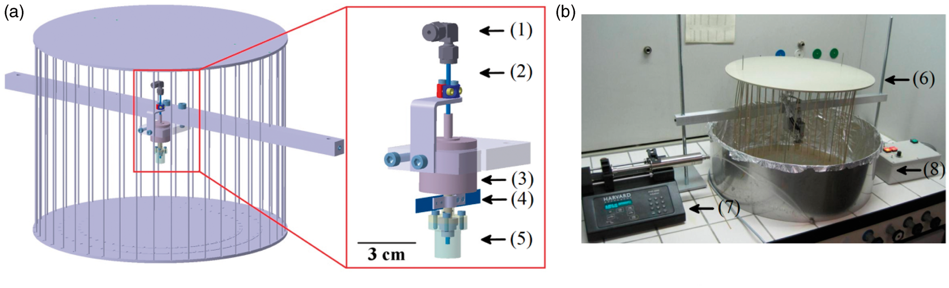
The syringe pump was started (feeding rate: 2 cm3/min) and as soon as the precursor completely filled the reservoir (appeared in the orifices), spinning at 5000 rpm was initiated.
As soon as the whole precursor was pumped into the spinneret, the syringe pump was stopped and the fibers were collected on a standard scanning electron microscope (SEM) holder with carbon tape (for SEM analysis) or a corundum plate for further calcination.
The morphology analysis of the fibers was performed on a NovaNanoSEM 230 (FEI, USA) at 7.00 kV acceleration voltage after sputtering a gold layer (coating duration of 45 s, Sputter Coater 108auto, Cressington, UK) onto the fibers to prevent the charging effect during SEM analyses.
The diameters of the fibers were measured on SEM micrographs (at least 100 of each type with the exception of S2715 before debinding, where only 73 fibers were measured). In order to obtain better statistical representations, three diameters were measured for each fiber and only their average was taken into account in the final size calculations. To find an optimal debinding temperature, thermogravimetric and simultaneous differential thermal analysis (TG/SDTA) measurements of PEO and Fe2O3 powders were conducted at the rate of 25℃/min in the temperature range of 30–1000℃ with the use of a TG/DTA 851, Mettler Toledo.
X-ray diffraction analysis was performed to compare the two iron oxide powders by means of chemical composition with the use of a PANalytycal X’pert Pro MPD equipped with a Johanson monochromator (Cu-Kα, λ = 1.540598 Å, 45 kV, 40 mA), the Netherlands.
To evaluate surface properties of the powders, zeta potential was analyzed (ZetaProbe, Colloidal Dynamics, USA) with changing pH (in the range of 5.5–12.0 in both directions (acidic to basic and basic to acidic). Measurements of ζ-potential of calcinated (500℃, 1 hour) iron oxide powders are also included. These analyses were performed to ensure that Fe2O3 will not change its surface properties after debinding.
Particle size distribution of the precursors has been measured by laser diffraction (LS230, Beckmann Coulter, USA).
Results and discussion
Results of ζ-potential measurements of iron oxide powders are presented in Figure 2. The measurements were performed on 10% suspensions in which the pH was adjusted with 1 M HCl and 1 M NaOH accordingly. Selected Fe2O3 powders exhibit isoelectric points (IEPs) of approximately 8.1 and 4.5 for S2715 and S2818 powders, respectively (see Figure 3(a) and (b)). Such a low IEP of S2818 is surprising, since a typical iron oxide IEP lies in the range of 9. To ensure there is no organic surfactant adsorbed on the surface (which could cause the shift of IEP), the powders were heated up to 500℃ for one hour and the zeta potential measurements were repeated. We did not observe any significant change in IEP of the heat-treated powders (a shift from 8.1 to 8.2 and 4.5 to 4.2 for S2715 and S2818, respectively). Thus, such a low IEP of S2818 was not caused by an organic additive. However, there still might be an inorganic modifier such as amorphous SiO2, present in the powder, which was not removed during the heat treatment.
ζ-potential of the iron oxide powders: (a) S2715; (b) S2818. X-ray diffraction patterns of the iron oxide powders.

Although the negative surface charge in neutral pH does not cover the application chosen in this work, we still decided to evaluate S2818 powder for comparison and a feasibility study of ceramic fiber formation with the use of RJS.
Phase analysis of the powders (see Figure 3) reveals that both iron oxide powders are mainly composed of a hematite (α-Fe2O3) phase. However, S2715 exhibits much higher crystallinity than S2818. Broader and less intense hematite peaks were observed in the S2818 diffractogram, suggesting the more amorphous nature of this powder. This is possibly one of the reasons for the very low IEP (for iron oxide) of this powder.
TG/SDTA results of Fe2O3 and PEO powders are presented in Figures 4 and 5, respectively. The measurement was performed at 25℃/min in the range of 25–1000℃. Thermogravimetric and differential thermal analyses revealed (see Figure 5) two significant differences between S2715 and S2818 iron oxide powders.
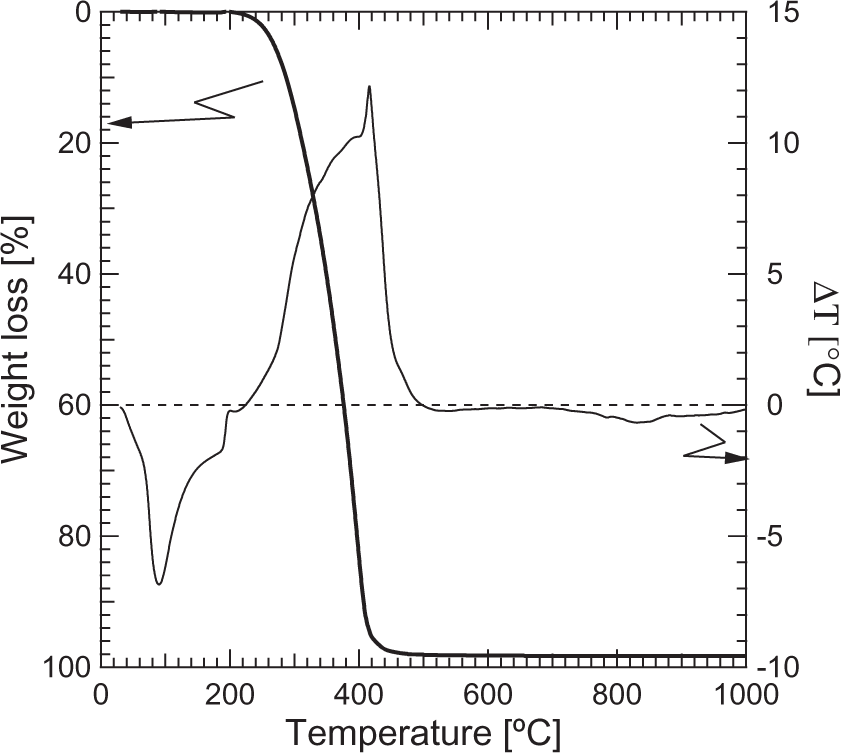
Thermogravimetric and simultaneous differential thermal analysis of the iron oxide powders: (a) S2715; (b) S2818. Thermogravimetric and simultaneous differential thermal analysis of the poly(ethylene oxide).
The S2715 powder is characterized by approximately 3% weight loss reached at 700℃. The total weight loss of S2818 powder was more than twice as high as for S2715 (approx. 7.3%). In addition, an endothermal peak was observed in the range of 30–340℃ where the highest weight loss was also observed. The DTA characteristics of S2818 in higher temperatures remained the same as for S2715. We suppose that S2818 might be a mixture of iron oxide and hydroxide (i.e. goethite), which decomposes in the range of temperatures of the aforementioned endothermal peak and thus additional weight loss was detected. This might be the second reason for the unusual ζ-potential curve for this powder.
As can be seen in Figure 5, PEO decomposes almost completely at 400℃ and thus the temperature of 500℃ was chosen for debinding of the composite polymer/ceramic fibers to ensure total removal of the organic additive.
An electrostatic stabilization was chosen to prepare stable aqueous suspensions of the Sicotrans nanopowders.
This type of stabilization prevents agglomeration of the particles by selecting the pH in which particle relative surface charge (either positive or negative) is the highest. High relative surface charge prevents particles from approaching. According to the Derjaguin, Verway, Landau and Overbeek (DLVO) theory, 27 van der Waals forces would take advantage and possibly cause agglomeration. The realization of electrostatic stabilization was done by selecting pH values of 4.0 (ζ ≈ 50 mV) and 9.0 (ζ ≈ −15 mV) for milling for S2715 and S2818 powders, respectively.
One hour of vibrational milling together with electrostatic stabilization of S2715 precursor dispersions resulted in approximately unimodal size distribution (see Figure 6(a)) of the particles and the average particle size of 0.127 µm. S2818 suspensions exhibited a broader size distribution, while still maintaining average size of the particles of 0.241 µm (see Figure 6(b)).
Particle size distribution of the iron oxide powders in aqueous suspensions: (a) S2715; (b) S2818.
Figure 7 presents results of rheology measurements of the aqueous polymeric solution and polymer/ceramic suspensions. The measurement was performed in the range of 1–1000 s−1 shear rate at room temperature.
Flow curves of the iron oxide precursors.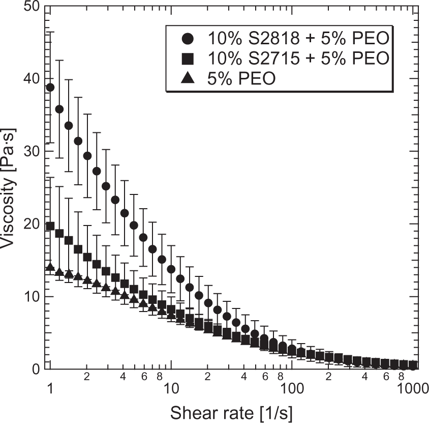
Prepared precursor dispersions (after milling and addition of PEO) were analyzed in terms of rheological behavior (see Figure 7). A viscous medium loaded with nanoparticles typically tends to clog tubings and is a well-known issue in extrusion and similar systems. All analyzed precursor suspensions exhibit a shear-thinning effect, which is advantageous for the pumping system. As expected, PEO has the largest impact on viscosity. The long chains of this polymer not only make dissolution more difficult, but also increase the viscosity of the aqueous solution significantly. The addition of 10% S2715 powder increases the viscosity by 43% (19.7 Pa s) at 1 s−1, whereas the same amount of S2818 powder raises it by 179% (38.8 Pa s) in the same shear rate conditions.
The effect of S2715 powder disappears at the shear rate 40 s−1, where the viscosity of 10% S2715+5% PEO suspension equalizes the viscosity of pure 5% PEO solution. The viscosity of 10% S2818+5% PEO equals that of 5% PEO at 115 s−1. This result suggests a higher degree of agglomeration of S2818 particles in suspensions. The reason is a small relative ζ-potential of S2818 powder (ζ ≈ 15 mV), which does not provide sufficient repulsion force to prevent the particles from approaching. In contrast, S2715 particles were stable and their addition to the precursor increased the viscosity only to a small extent.
The diameter size distribution of the composite fibers is shown in Figure 8. The fibers are approximately 0.7 µm. The size is of wide distribution and is comparable for both types of iron oxide. The lack of change in diameter of the debound S2818 fibers leads to a conclusion that there might be a segregation of ceramic particles in the fiber volume. As soon as precursor jets exit spinneret orifices, they shrink due to the air flow and solvent evaporation. The decrease in volume of the polymer/ceramic jet causes tension and segregation of the non-plastic ceramic particles. This fact allows us to assume that particles might be moved to the outer layers in this process with PEO being located mainly in the core of the fibers. Such composition would lead to only minor changes in fiber diameter and increase porosity after polymer removal.
Fiber diameter size distribution: (a) S2715 composite fibers; (b) S2818 composite fibers; (c) S2715 debound fibers; (d) S2818 debound fibers.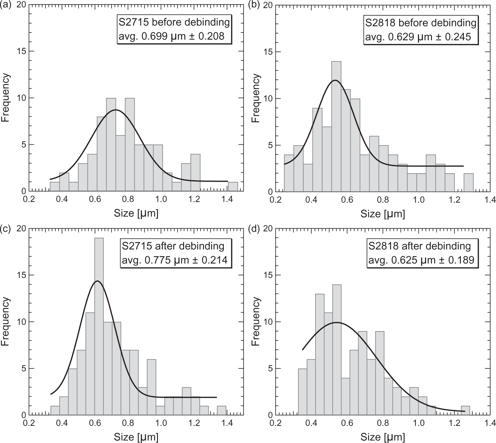
SEM micrographs of the composite (before debinding) polymer/ceramic fibers are shown in Figure 9. The measurements were performed on a NovaNanoSEM 230 (FEI, USA) at 7.00 kV acceleration voltage after sputtering a gold layer (coating duration of 45 s, Sputter Coater 108auto, Cressington, UK) onto the fibers to prevent the charging effect during SEM analyses.
Scanning electron micrographs of the spun fibers: (a) S2715 composite fibers; (b) S2818 composite fibers; (c) S2715 debound fibers; (d) S2818 debound fibers. Magnification: 10,000×.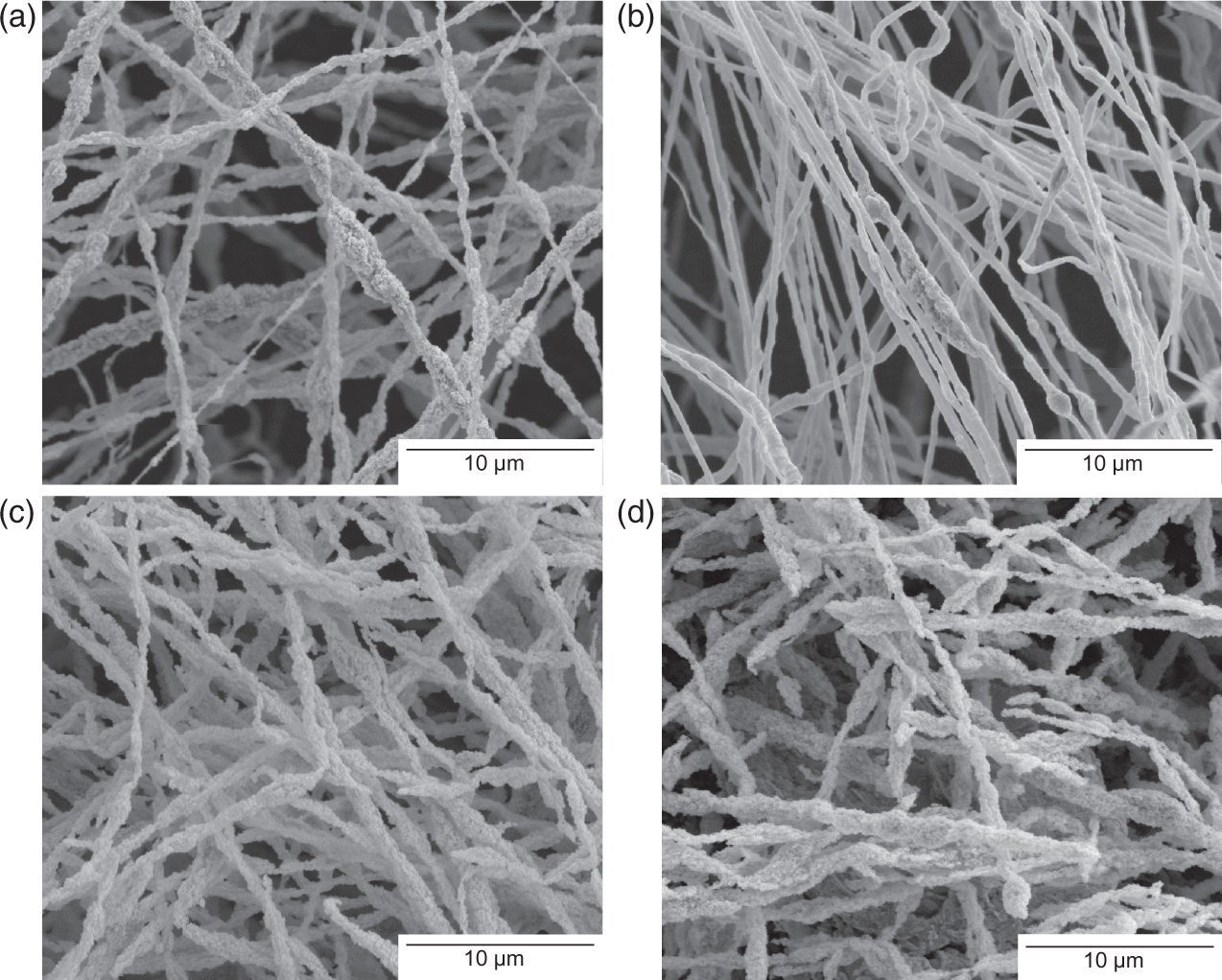
The microstructure of the obtained fibers is presented in Figure 9. The composite polymer/ceramic fibers made of S2715 and S2818 are long and continuous. The length of fibers is larger than 100 µm. They are of irregular, but mostly of cylindrical shape. The fibers have a well-developed surface with open pores. Despite a slight difference in nanoparticle size in precursors, there is no significant difference in morphology of the fibers between the two Sicotrans powders.
Debinding of both types of fibers leads to a significant decrease of mechanical strength. The fibers are brittle and can break during manual manipulation. This is due to the fact that the binding polymer was removed by thermal treatment and only the iron oxide nanoparticles were left in the fiber volume. In addition, the removed polymer created open porosity, which contributes to the lowered mechanical properties of the fibers. This could be solved by choosing a different heating program and sintering the nanoparticles, the addition of binders and/or glass formers or simply more constituents that react with the base material. However, we wanted to avoid sintering of the particles to preserve the very well-developed surface of the fibers. Heat-treated fibers are shorter compared to the composites. This is possibly because of their breakage during manual manipulation and/or a collapse of the nanoparticles in the fiber volume due to the removal of PEO in their narrowest points.
Based on the micrographs we claim the open porosity seems to be increased because of the removal of PEO during debinding. Although the pores would not be penetrated during filtration due to typically high flow rates of a liquid, they improve the surface development of the spun fibers.
Conclusions
The composite polymer/ceramic fibers based on hematite were successfully spun. Transformation into purely ceramic fibers was also achieved. However, there is still room for improvement in terms of mechanical properties of the ceramic fibers (especially in filtration applications where the fibers are under fluid flow). Although it is possible to handle them manually, stronger forces may break them into needle-like structures.
It is worth emphasizing that in this work we used a very simple composition, namely: solvent, ceramic nanopowders and fiber-forming agent. It is very likely that the addition of more ceramic phases, especially glass formers, will provide additional mechanical improvements.
We assume that the produced fibers are characterized by high adsorption capacity resulting from a very well-developed surface area, which makes them a viable option for adsorption applications.28–30 Electrostatically stabilized Fe2O3 dispersion combined with PEO water solution provides an environmentally friendly and cost-effective precursor for fiber formation with the use of the RJS method. Furthermore, it has been proved that RJS constitutes an alternative for production of fibers. This technique minimizes or eliminates limitations associated with the methods presently used for fabricating fibers.
Footnotes
Funding
This work was supported by Switzerland through the Swiss Contribution to the enlarged European Union within the project “Novel nanocomposite filter media for adsorption based water treatment – NANOSORP”, PSRP: 209/2010.
Acknowledgments
We would like to thank Mr Heinz Altorfer for his tremendous help with designing and realization of the spinneret and Dr. Jakub Michalski for fruitful discussions.