
Abstract
We report the effect of glass fiber structure and the epoxy polymer system on the flexural strength, interlaminar shear stress (ILSS), and energy absorption properties of glass fiber-reinforced polymer (GFRP) composites. Four different GFRP composites were fabricated from two glass fiber textiles of different fabric count and strand density and two resin systems, a cycloaliphatic and a linear aliphatic system. These composites were fabricated using the vacuum-assisted resin transfer method. The flexural stress and ILSS data were obtained using a three-point bending test following ASTM 790-10 and ASTM D2344/D2344M standards. The GFRP composite sheet fabricated using a larger fabric count showed weak flexural strength as well as poor ILSS properties. However, it showed an average increase in energy dissipation of 95% and 7%, for resins SC780 and SC15, respectively, after five compression cycles over the measured range of compression strain. In comparison with the SC15 resin, the SC780 resin proved to have better flexural and ILSS properties but decreased energy dissipation. The results of this investigation help with the design of textile-reinforced composites for applications where bending strength, ILSS, and energy absorption are important.
Keywords
Composite materials are ideal for structural applications where high strength-to-weight ratio and stiffness-to-weight ratios are important. Aircraft and the space vehicle manufacturing industries are the primary users of composites, especially glass fiber-reinforced polymer (GFRP) composites. A lighter panel is easier to transport, lowers the risk of structural damage, and reduces the cost of shipping. Apart from the aerospace industry, these GFRPs are used for force protection, automotive body and engine parts, bridges, and building and other infrastructure applications worldwide.1–6 The basic components of these composite panels include a thermosetting polymer resin embedded between woven glass fiber reinforcement fabric.
Regardless of all the excellent mechanical properties of GFRP composites, such as tensile strength, compression strength, flexural strength, and in-plane shear strength, researchers continue to investigate ways to improve the interlaminar shear stress (ILSS) and energy absorption capacity. To improve the ILSS properties, the interlaminar adhesion and binding can be optimized during the composite fabrication, while the properties of the reinforcement and matrix material can be improved. One of the standard composite fabrication techniques is called the vacuum-assisted resin transfer method (VARTM). This method results in a higher fiber-to-matrix volume ratio and enhances the resin infusion through the composite thickness resulting in a reduction of voids between the layers, which improves the GFRP composite ILSS properties. 7
The reinforcement fabric structure, including type of weave, warps and fill density, and thickness, has a significant effect on the composite’s mechanical properties. Three basic weave patterns of woven textiles have been investigated by research groups for their effect on the composite’s mechanical properties. The plain weave textile structures show excellent axial tensile and compression, fatigue, and in-plane shear properties and so have been widely used in GFRPs.8–11 It has also been shown that a greater strand density provides greater homogeneous fiber distribution through the resin-rich regions of the composite, resulting in an improvement of the interlaminar fracture toughness. 12
The diameter of the glass fiber and its surface microstructure and chemical functionality have a direct effect on interlaminar fracture properties. A smaller diameter strand has a shorter linear crack length, which leads to a higher resistance to crack propagation and penetration and ultimately to increased resistance to failure. 13 In woven textiles, warp and fill strands generate crimp (waviness) due to their interlacement. 14 The waviness in the fabric produces local stress perturbations under uniaxial tension load, which causes large strain concentration and may result in fiber and matrix debonding or matrix cracking. The waviness can also cause local fiber buckling under compression.15,16 By altering the waviness through changing the fiber thickness and warp and fill, the mechanical properties of the GFRP composite can be controlled.
In this investigation, the effect of the glass fabric structure (fiber count, weave density, and fiber diameter) and the polymer matrix on the flexural, ILSS, and cyclic compression properties of GFRP composites were studied. In addition, the energy absorbed or dissipated per unit volume was derived from the cyclic compression measurements. A total of four GFRP composite combinations were studied, which were fabricated using the VARTM. These properties are useful in selecting the glass fabric and resin systems for high-performance GFRP composites for energy absorption in buildings, equipment, and other structures.
Experimental details
Materials
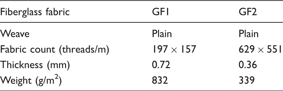
Glass fabric specifications
Composite sheet fabrication
The composite sheets were fabricated using the VARTM, which uses a vacuum bag and pump to facilitate resin flow and reduce the presence of air bubbles in the resin. This results in a reduction of voids, which decrease the strength of the composite.
7
A total of four combinations of GFRP samples were fabricated, one from each combination of the two glass fabrics, GF1 and GF2, and the two resin systems, SC15 and SC780 (Figure 1). The glass fabrics were cut to a size of 38 cm × 46 cm. The cut fabrics were laid over each other so that the warp strands were oriented in the same direction for all layers; however, random nesting was used, which means that relative positions of the warp strands perpendicular to the fiber direction was random.8,11,13 Seven layers of GF1 were used to make an approximately 5-mm thick GFRP composite. Similarly, 12 layers of GF2 were needed to make an approximately 5-mm thick GFRP composite.
Optical images of glass fabric samples (a) GF1 and (b) GF2. (c) Glass fiber reinforced polymer samples showing the four different combinations of glass fabrics and resins, as labeled.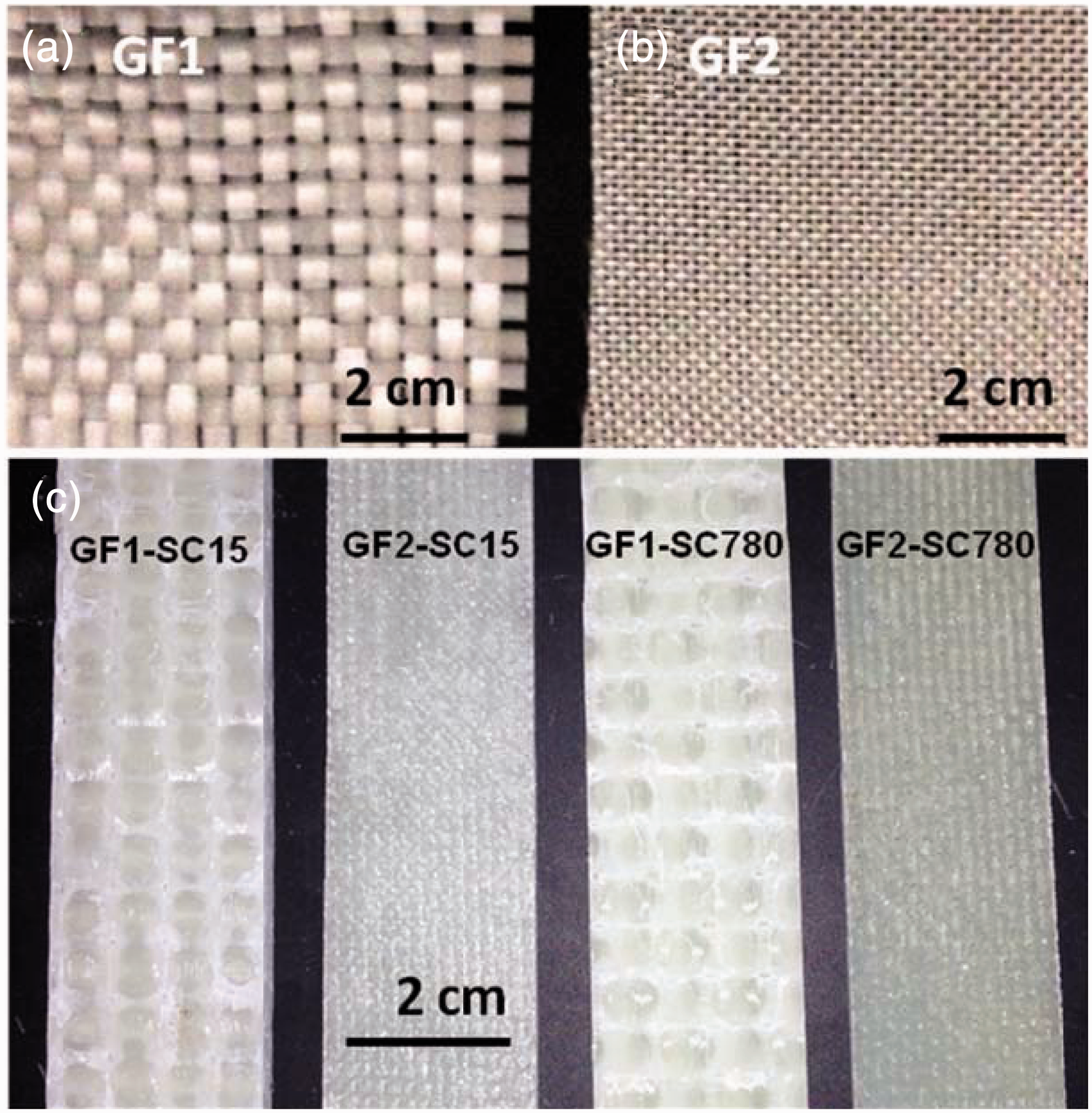
The stacks of glass fiber layers were inserted into separate vacuum bags with a series of feed tubes to enable a continuous supply of resin. A distribution medium was also inserted into the bag to facilitate the resin flow and achieve a more uniform flow distribution. The vacuum bag was then pumped down to a pressure of about 125 Torr and held there for 1 hour to degas the system. Simultaneously, the resin solution was prepared according to the manufacturer’s recommendation as follows. A total of four GFRP composite combinations were prepared with the two glass fibers and the two resin systems. There are two components in each resin system, a resin (part A) and a hardener (part B). The ratio of resin to hardener was set to 100:30 by weight for SC15 and 100:22 by weight for SC780 systems, as per the manufacturers’ guidelines. Part B was mixed into Part A and stirred for 5 min at about 300 rpm using a RW20 digital stirrer (IKA, Wilmington, NC).The resin solutions were then degasified for 10 min under separate vacuum systems. The resin solutions were then infused through their respective VARTM system for approximately 25–35 min until all fabric layers were wet. The pressure inside the vacuum bags was held constant at about 125 Torr for 24 h to remove residual resin and vapors and to pre-cure the composite under pressure. The samples were then removed from the vacuum bags and post-cured for 4 h at a temperature of 90℃ in an oven (Model CE3G, Sheldon manufacturing, INC, Cornelius, OR, USA).
Flexural rigidity
Flexural rigidity measurements were performed according to ASTM 790-10.
18
The tests were conducted with an MTS servo hydraulic device model 311-11904.98 (Eden Prairie, MN, USA) using a 222.4 kN load cell with a noise level of 13.3 N. The test samples were cut using a diamond blade saw. A span length-to-thickness ratio of 16:1 was maintained for the test according to the ASTM standard. The cross-head motion rate (R) was set according to the ASTM standard, which was calculated for each sample using Equation (1):


Summary of flexural test results

GFRP: glass fiber-reinforced polymer.

Flexural stress versus strain behavior for (a) GF1-SC15, (b) GF2-SC15, (c) GF1-SC780, and (d) GF2-SC780. (e) Schematic of flexural rigidity measurements.
Interlaminar shear stress
The ILSS was measured using a three-point short-beam bending test following ASTM D-2344-00.
19
These measurements were also conducted on the MTS servohydraulic machine using a 1.27 mm/min cross-head speed. The sample size was selected as per ASTM 2344-00, where the sample length is equal to six times the sample thickness and the width is two times the thickness. Five samples for each GFRP configuration have been measured. The ultimate breaking load was used for calculating the ILSS, which is given by Equation (5):
(a) Interlaminar shear stress (ILSS) measurements for five samples each of the four glass fiber-reinforced polymer composites: GF1-SC15 (
 ), GF1-SC780 (
 ), and GF2-SC780 (
 ). Squares represent composites made with GF1, circles represent GF2, filled shapes represent SC15, and unfilled shapes represent SC780. (b) Summary of the ILSS values. (c) Schematic of ILSS measurement.
Cyclic compression
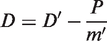
To determine the cyclic compressive stress versus strain and energy dissipation, the samples were measured using the MTS servo hydraulic device. The load versus displacement was measured and converted into stress–strain by applying Equations (6) and (7):


The energy density and absorption properties of the GFRP composites, the dissipated energy density Ed, was calculated by integrating the stress–strain curve to find the area enclosed by the curve according to Equation (8). The dissipated energy density as a function of cycle number is presented in Figure 4:
(a) Dissipated energy density in glass fiber-reinforced polymer composite samples for the four combinations of glass fiber and resin materials. (b) The table shows the dissipated energy per unit volume for the four composite combinations for the fifth cycle. (c) Schematic of the compression energy measurement, where P is the load.

Rupture analysis using scanning electron microscope
Both the unmeasured and the short-beam tested samples for the four GFRP composite combinations were sputter coated with gold for 2 min at a current of 45 mA using the Denton Desk-II (Denton Vacuum LLC., Moorestown, NJ) to reduce charging effects. The sample was imaged using a JEOL JSM 6390 SEM (JEOL USA Inc., Peabody, MA) using an accelerating voltage of 5 kV and a working distance of 10 mm. Figure 5 shows the scanning electron microscope (SEM) micrographs.
Micrographs of interlaminar shear stress (ILSS) samples and failure analysis. Each row (a)–(d) shows scanning electron microscope images for one combination of glass fabric and resin used to make the glass fiber-reinforced polymer (GFRP) composites. The first column shows a representative cross-section of the approximately 5-mm thick GFRP composite sample. The second and third columns show representative images of the cross-section after measuring the ILSS value from the three-point short-beam bending test. Arrows point to ILSS failure, ovals locate fiber rupture zones, and the rectangle shows a resin-rich location.
Results and discussion
The composite sheets were fabricated using a VARTM system from two different glass fabrics (GF1 and GF2), each having a different thickness and weight, and two different resins (SC15 and SC780), and each having different chemical hardening agents. Figure 1 shows the two glass fabrics used and the composite samples prepared for evaluation. Figure 2(a)–(d) show the flexural test data, which illustrate the stress versus strain behavior of the composites fabricated with GF1-SC15, GF2-SC15, GF1-SC780, and GF2-SC780, respectively. Table 2 lists the ultimate strength, yield strength, and Young’s modulus of each GFRP composite combination. For the GF1-SC15 combination, the ultimate strength was 182 MPa, which was the lowest among the four combinations. The GFRP composite fabricated with the same SC15 resin but with glass fabric GF2, which has a higher compact ratio and finer strand density, resulted in 24% higher ultimate strength. A similar trend was also found with the resin SC780 where the increase in ultimate strength was 82%. This can be explained by the waviness in the strand due to the thicker fabric, which makes the strand weaker under the load. 20 Furthermore, the GF2 composite has a higher density of glass due to its lower fiber diameter resulting in a stronger composite. Independent of glass fabric type, composites fabricated with SC780 possessed higher ultimate strength since they had a stronger binding to both glass fiber types. Some of this difference in strength can be attributed to the difference in strength of the individual resins, since SC780 has a 10.3% higher strength than SC15.17,21 The ultimate strength of the SC780 composites was higher than the SC15 composites by 21% for GF1 and 77% for GF2. This can also be due in part to a greater diffusion of the SC780 resin through the glass fabric material during the infusion process, resulting in few voids, as shown in the first column of Figure 5. Furthermore, SC780 is a linear aliphatic resin and has stronger bonding with the coupling agent on the glass fabrics. 22 For a given glass fiber type, the Young’s modulus was higher for the SC780 composites by 1.6% for GF1 and 28.3% for GF2. Considering that the modulus of SC780 is larger by 7.7% compared to SC15, 17 there was no significant increase in the modulus for GF1 composites regardless of resin type. However, in thinner glass fabrics, such as GF2, the modulus was higher by 7.0% for SC15 and 35.1% for SC780 compared to GF1. The increased modulus in GF2 composites can be attributed to less strand movement.
Interlaminar shear stress
A three-point short-beam measurement was performed to obtain the ILSS properties of the GFRP according to the ASTM D 2344-00. Figure 3 shows the ILSS results of the four different glass fabric and resin combinations. The composites fabricated with the thinner GF2 fabric show a significantly higher ILSS than the one made with the thicker GF1 fabric by a factor of 2.0 when using SC15 and 2.48 when using SC780. Larger ILSS in thinner glass fabrics can be attributed to more surface area being in contact with the resin, which provides a greater shear resistance.
The adjacent layer nesting effect is negligible in the thinner GF2 fabric allowing it to have greater interlaminar fiber bridging due to extended surface area of the finer GF2. Moreover, the type of resin used as the matrix material alters the ILSS properties. For the composites fabricated with GF2 and SC780, the ILSS is 5519 MPa, which is the highest value of all glass fabric and resin combinations investigated here. The GFRPs fabricated with GF1 and SC15 revealed the lowest value of ILSS, which is 1156 MPa. This can be explained by the fact that this combination resulted in the largest void structures between the glass fabric and the matrix material, as shown in the first column of Figure 5(a) and thus had a small surface contact area and weak binding between the glass fiber and the resin. These results are similar to the flexural test, where the thinner fabric was able to reach a higher stress before failure.
Cyclic compression and energy dissipation
To evaluate the glass fabric thickness effect on the energy absorption capability of GFRP materials, cyclic compression measurements were performed. A cyclic load was applied to the sample with an applied force rate of 178 N/s, while load versus displacement was measured. This was converted into a stress versus strain curve (Figure 6). All measurements showed hysteresis in the stress versus strain curve under cyclic loading, which resulted in an enclosed area. This area was calculated and identified with the dissipated energy per unit volume. The amount of energy dissipation changes with the glass fabric and resin type. Each of the four composite combinations showed the largest energy dissipation in the first cycle, which was reduced in subsequent cycles. The energy dissipation was reduced after each cycle due to hardening that occurs in the GFRP composite.
Representative cyclic compression measurement showing hysteresis (energy absorption) of glass fiber-reinforced polymer composite samples fabricated with two different glass fabrics and two matrix resins.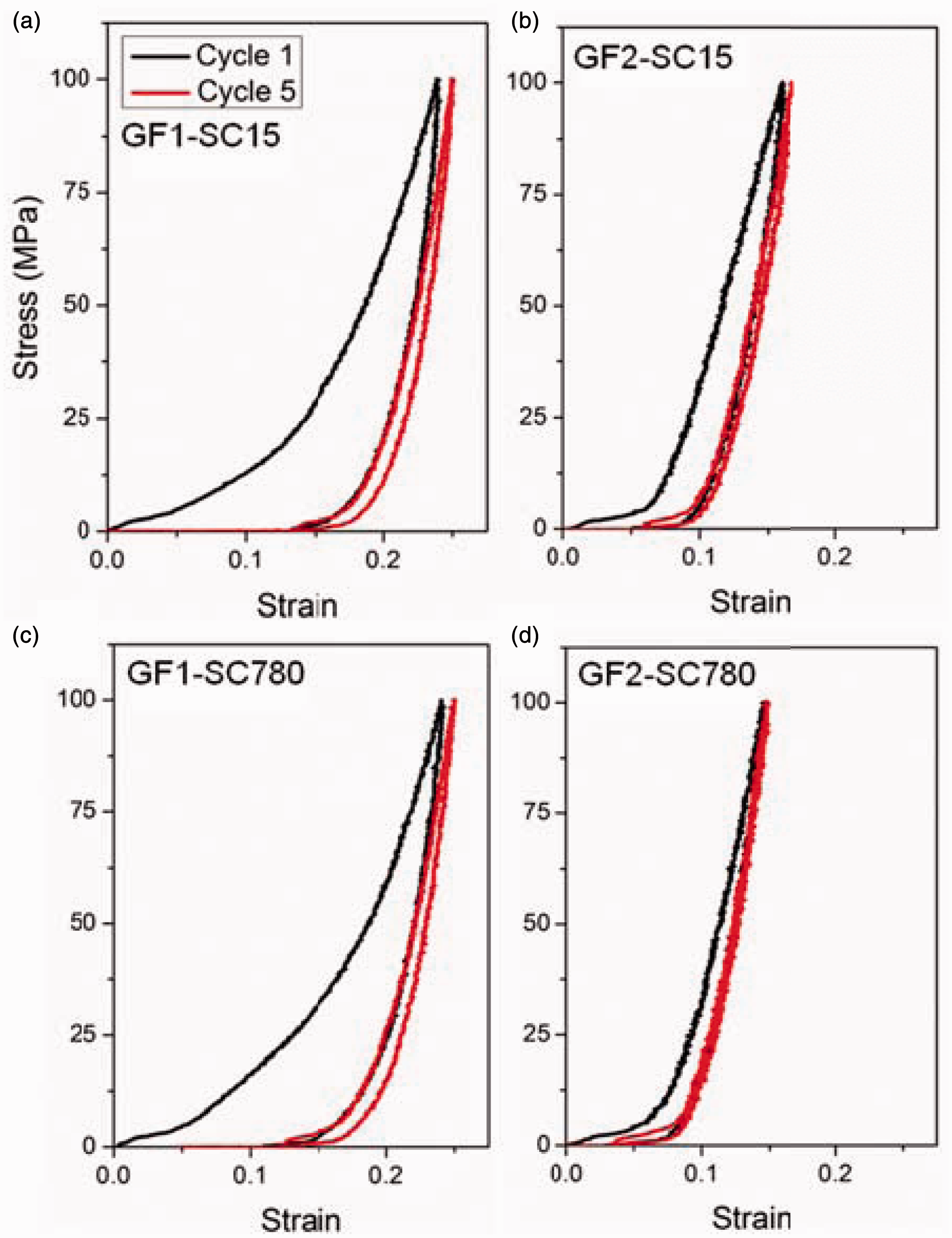
Figure 4 shows the dissipated energy versus cycle for all four combinations of glass fiber and resins. Each data point is obtained by averaging the dissipated energy density on that cycle over four samples. GFRP composites fabricated with GF1 result in a higher energy dissipation when compared with GFRPs made using GF2. This behavior can be attributed to the fiber movement within the fabric under compressive loading.12,23 The relative motion of fibers within the fiber bundle help to dissipate more energy due to friction. The GFRP composites made with GF1 show similar levels of dissipated energy for the two resins but the level is higher in the SC780-based composite by 14% after five cycles. For GFRP composites made with GF2, the SC15-based composite had a higher energy dissipation than SC780 composites by 60% after five cycles. This can be explained by the cycloaliphatic chemical structure, which provides higher cross-linking with the reinforcement element. 22 Compared to GF2 composites, the GF1 composites dissipated 6.7% greater energy for SC15-based composites and 95% for SC780-based composites after five cycles. The combination that gave the greatest energy dissipated was GF1-SC780, while the least energy density was dissipated by the GF2-SC780 composites.
Failure analysis
The ILSS of the GFRP composites was determined using the three-point short-beam theory. The results indicate that the ILSS of the composites are significantly greater than their flexural yield strength. This can be explained by analyzing the failure modes of the measured samples using a SEM. The failure modes were caused by interlaminar shearing, flexural yield, or a combination of the two. 23 Interlaminar shear failure is characterized by the opening of a void between the planes. Flexural yield failure is characterized by fiber rupture, which may result from plane bending. Figure 5(a)–(d) show that the failure in ILSS occurred not only due to interlaminar shear, but also as a result of a complex mixed mode of flexural yield and interlaminar shear failure. Figure 5(a) shows that the failure was a complex mode of interlaminar shearing and rupture of resin. It occurred at the contact point between the two layers and penetrated at the resin-rich site. The GFRP made from GF2 and SC780 is quite different in nature (Figure 5(d)). It shows a mixed mode of interlaminar shear and bending (fiber ruptured). A similar behavior is also observed in GF1-SC780-based composites (Figure 5 c)), where both fiber rupture and interlaminar shear are present. In the case of GF2-SC15 (Figure 5(b)), the ILSS failure occurred due to GF2 peeling off of the resin surface at a boundary layer interface, which is characteristic of interlaminar shear failure. There was also some minor fiber rupture. In each case, the crack propagation was perpendicular to the applied force. This indicates the failure mostly occurred due to shear rather than bending.
Conclusion
In this study, GFRP composites were fabricated using four combinations of glass fabrics and resins. The flexural, ILSS, and the energy dissipation properties of these GFRP composites were measured. Among the various glass fabrics and resins that were studied here, the glass fabrics and resins that are weak in bending and ILSS were superior in energy dissipation and those that were stronger in bending and ILSS were inferior in energy absorption. The flexural and ILSS test data indicate that the thinner GF2 fabric (with a linear aliphatic resin matrix material) has excellent flexural and ILSS properties, while the cyclic compression measurements revealed poor energy dissipation. The cyclic compressive and energy dissipation measurements suggest that the thicker GF1 fabric has better energy dissipation properties independent of the resin matrix. The ILSS failure in SC15 resin-based composites was observed to be in the simple mode, while in SC780 composites it was observed to be in the complex mode, which includes both interlaminar shear and bending failure. In addition, both the flexural strength and the ILSS were significantly greater for composites fabricated using SC780. This reveals that the SC780 resin has stronger bonding properties to both glass fiber fabrics than the SC15 resin. It is important to select the proper combination of glass fabric and matrix resin material to meet the needs of an application. This study sheds some light on how both the glass fiber reinforcement material and the resin matrix are both important parameters to consider in the design of various structures that may be subject to a wide range of loading conditions. Future work in this area will include a more intense study involving the interaction between the glass fiber and resin matrix systems and how this impacts the overall mechanical properties and energy dissipation capacity of GFRP composites.
Footnotes
Funding
Mr. Jignesh S. Patel and Dr. Matthew W. Brenner were supported by an Oak Ridge Institute for Science and Education (ORISE) postdoctoral fellowship under contract number DE-AC05-06OR23100 between US Army ERDC and the US Department of Energy.
Disclaimer
The names of commercial glass fabrics and polymer resins and manufacturers are provided for identification purposes only. The results reported herein were derived from a limited set of experimental conditions that may not represent the optimal performance range for all products.