



Abstract
Luminous fiber embroidered fabric with a long afterglow effect is prepared by luminous fiber through a computer-aided embroidery machine. As the main raw material, rare earth luminescent material and polymer are used to produce the luminous fiber by the melt spinning process. In this research, the light-emitting portion of the fabric, which uses the principle of superposition of light, is designed by multi-layer construction in computer-aided design software. The afterglow performance of the designed fabric has been characterized. As a result, the size of stitch spacing is inversely proportional to the afterglow intensity of the fabric, and the fabric with a tatami needle has the maximum afterglow intensity in this experiment. Compared to the fabric with non-superimposed stitches in layers, the luminous fabric with superimposed stitches has higher brightness, longer duration of emitting light, and better stable luminescent properties.
Keywords
Luminous fiber fabric is usually produced by weaving, knitting or embroidering rare earth luminous fibers into fabric. Luminous fiber embroidered fabric can be embroidered by computer-aided embroidery machine. Wilcom 9.0 software, which is a professional computer-aided design (CAD) software for plate-making of embroidery, can be used for the pattern design of luminous fiber embroidered fabric. Such fabric not only has the decorative function of traditional embroidered fabric under the illumination condition, but also gives out visible light in the night. Usually, luminous fiber embroidered fabric mainly emits yellow, yellow-green, green, and blue light at night. After the fabric absorbs visible light and stores light energy, it emits light in the darkness for more than 10 hours. In addition, it is non-toxic, non-radioactive, and can be recycled. 1
Luminous fiber embroidered fabric has the function of storing and emitting light and can be easily recognized even in the darkness. It is considered as a high-tech product.2–4 The main source of light emission of luminous fiber embroidered fabric comes from divalent europium ion (Eu2+) activated strontium aluminate phosphors (SrAl204: Eu2+, Dy3+) in the luminous fiber, especially the Eu2+ ions from 4f65d 1 to 4f 7 .5–7 However, trivalent dysprosium ions (Dy3+) are not involved in the fluorescence emission, and their influence on the fluorescence excitation and emission process is controversial.8–13
Luminous fiber products mainly include knitted fabrics, woven fabrics, plush toys, art embroidery, and other decorations. 14 In 2007, Ge et al. 15 patented the luminous fiber embroidery. Rare earth luminous fiber creates special visual effects at night and plays a good role in the decoration and function when it is added into embroidery cloth and embroidery patterns. In 2012, Wang and Ge 16 developed hand embroidery by using luminous fiber threads. This laid the foundation for luminous fiber that can be used in handicraft, textile, and clothing design. From a practical application viewpoint, there are few researches to design and develop computer-aided embroidery. Furthermore, low efficiency of hand embroidery makes it unsuitable for mass production. From a technology viewpoint, the stitch parameter is the most important design element of the computer-aided embroidered fabric and can be easily controlled by a computer. Therefore, compared with hand embroidery, computer operation has more advantages in the process of production.
As a new functional luminous fabric, its afterglow property is particularly important for study. However, during the process of computer-aided embroidery, luminous fiber embroidered fabric is prone to continually wear among different parts of machine, which affects the luminous intensity of the fabric. Therefore, this paper focuses and addresses issues related to designing a pattern with gradient overlay using a layer style with the aim of improving afterglow characteristics, and evaluates afterglow performance of the designed fabric. Moreover, according to the superposition principle of light, the magnetic field of the meeting point of mixed light is caused by superposition of the magnetic field by each light source. The total light intensity is the sum of light intensity of each beam. 17 Consequently, by using a new and feasible method during the plate-making process, it is important that stitches with proportional overlay are designed to build multiple layers on the same embroidered bottom.
Design principles and methods
Design process
The difference between luminous embroidered fabric and traditional embroidered fabric is that luminous embroidered fabric presents both a decorative effect and luminous effect no matter whether it is under the condition of light or not. Usually, the pattern of luminous embroidered fabric is embroidered entirely by luminous embroidery threads and it contains two versions: the decorative pattern and the luminous pattern. The decorative pattern uses ordinary embroidery threads, while the luminous pattern uses luminous embroidery threads.
Nowadays, the CAD system for computer-aided embroidery, which produces a variety of embroidery stitches, makes it possible to superimpose stitches and clearly demonstrate the process of needling. As a commonly used CAD software, the Wilcom 9.0 software is capable of modifying and improving the quality of pattern design of embroidery.
18
The Fuyi computer-aided embroidery machine is a kind of mechanical and electrical product that can be used to make the embroidery process with the realization of high speed and high efficiency. The sequence of the work flow of luminous embroidered fabric is shown in Figure 1.
Work flow of luminous embroidered fabric design and production.
Principle of pattern superposition
In order to make the fabric have high initial brightness and last for a long time during the night, layers need to be properly superimposed by using the Wilcom plate-making software. The superposition principle of those three patterns is shown in Figure 2: decorative layer (a) with color a, luminous layer I (b) with color b, and luminous layer II (c) with color c. Those three layers can be edited separately in the CAD software and the superposition principle of the three layers is as follows: layer (a) is taken as the basic layer, layer (b) can be superposed on it to form new design, and layer (c) is superposed on the previous design to form the new pattern (d) with colors a, b, c, ab, ac, bc, abc. More attention should be paid to the effect of stitch type, stitch spacing, and size setting on tension of the embroidered bottom.
Superposition principle of three patterns: (a) decorative layer; (b) luminous layer I; (c) luminous layer II; (d) superposition layers.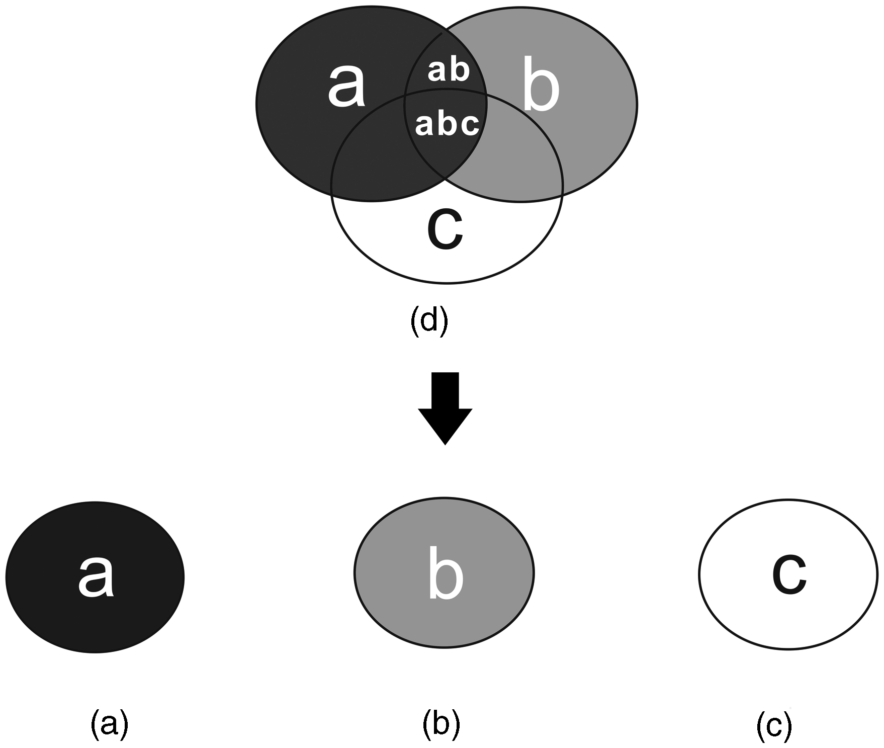
Organization structure design by computer-aided software
Four types of stitches and object properties
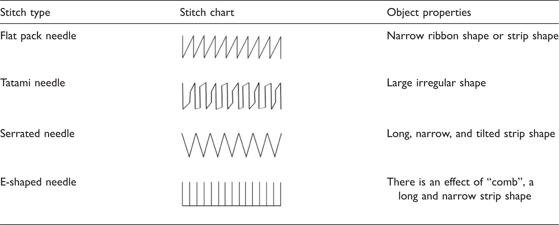
The layers are divided according to the colors of the embroidery threads. The luminous embroidered fabric with two layers could be produced, as shown in Figure 3. The red and green layers show large irregular shape and both use luminous embroidery threads and the tatami needle. However, the pattern of fabric in Figure 3 adopts a single design with no overlapping between different layers and no change with stitches. Furthermore, the luminous pattern is static and the emitting light contains only a flat color. Therefore, in order to get a good luminous performance, fabric parameters such as stitch type, stitch spacing, and superposition of stitches are designed by using CAD software.
Luminous fiber embroidered fabric with two layers: (a) decorative effect; (b) luminous effect.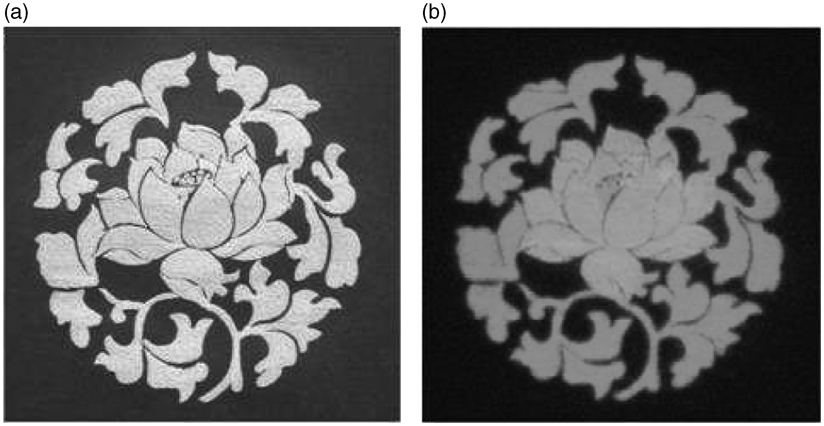
Experimental details
Materials
Materials such as normal polyester threads (9.72 tex/2) and paper liners for computer-aided embroidery were all purchased from Wuxi Yishiman Garment Accessories Co., Ltd. The rare earth luminescent materials (SrAl204: Eu2+, Dy3+) were purchased as spinning materials from Changshu Jianghui Fiber Products Technology Co., Ltd. The fiber-forming polymers (polyethylene terephthalate (PET) chips) were purchased from Wuxi Taiji Industry Co., Ltd. (Wuxi, China). Transparent inorganic pigments and functional additives were supplied by Jiangsu Guoda Complete Wiring Equipment Co., Ltd.
Methods
In this experiment, the colored luminous fibers (16.67 tex/36 f) were prepared by melt spinning, incorporating the luminescent particles at 5 wt%. 19 The fiber-forming polymers (PET chips) were dried in an oven at 110℃ for 24 hours, and then mixed with rare earth luminescent materials (at a dosage of 5%), transparent inorganic pigments, and functional additives in a high-speed mixer. Then, the mixtures were extruded by a twin-screw masterbatch producer at 270–290℃ to get colored luminous masterbatches for spinning application. After drying for 20 hours at 110℃, colored luminous masterbatches were melted at 250℃ with 3000 m/min winding speed and spun to obtain colored luminous fiber samples. Finally, the colored luminous fibers were twisted into luminous yarns on the twisting machine.
During the computer-aided embroidery process, multicolor luminous yarns (16.67 tex/2) and polyester threads (9.72 tex/2) were chosen to prepare luminous fiber embroidered fabric. The embroidering patterns were produced by the Wilcom 9.0 software and then input into the operating system of the computer-aided embroidery machine. By controlling the computer, the luminous fiber embroidered fabrics were finally finished.
Characteristic analysis
The afterglow intensity of luminous fiber embroidered fabric is assessed using a PR–305 long-ray fluorescence tester. Before testing, the samples must be placed in a dark place at least for 24 hours. The testing is carried out under the following condition: a room temperature, an excitation illumination level of 1000 lx, and an excitation time of 15 minutes.
Structure design with proportional superposition
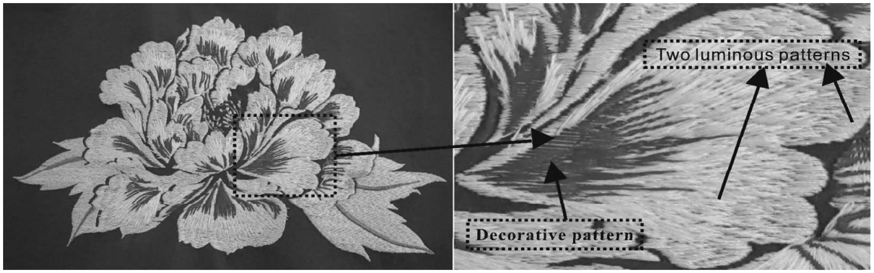
The peony flower is chosen for the pattern of the fabric, and this pattern is in accordance with the superposition principle of three patterns in Figure 2. Figure 4 shows the plate-making structure of the luminous peony fabric. As can be seen from Figure 4, the six separated layers have six kinds of colors. Layer 1, layer 2, and layer 4 use luminous threads that contain a petal pattern in white and pink colors and a leaf pattern in a light green color, while other petal patterns are in crimson color, the leaf vein pattern is in dark green color, and the blossom pattern in yellow color, which constitute decorative layer 3, layer 5, and layer 6. All those three layers use ordinary embroider threads. In addition, considering layer 3 is superimposed on layers 1 and 2 and the influence of stitches on the fabric tension, stitch spacing is set to 0.4 mm for layer 1, 0.5 mm for layer 2, and 0.6 mm for layer 3. Therefore, the ratio of the embroidery threads among these three layers is 4:5:6. Figure 5 shows the effect of the fabric of the whole and the part, which is made by the Fuyi computer-aided embroidery machine. In Figure 5, from an overall perspective, the luminous fabric performs good adornment effect in the daytime. Specifically, the petal pattern of the fabric is composed of three layers: one layer is the adornment layer that uses red ordinary embroidery threads, while the other two layers are luminous layers that use white and pink luminous threads. Finally, the unique design makes the fabric look brand-new and gives an even greater sense of layers.
Plate-making figure of the luminous peony flower using Wilcom 9.0 software. Effect of luminous fiber embroidered fabric of the whole and the part.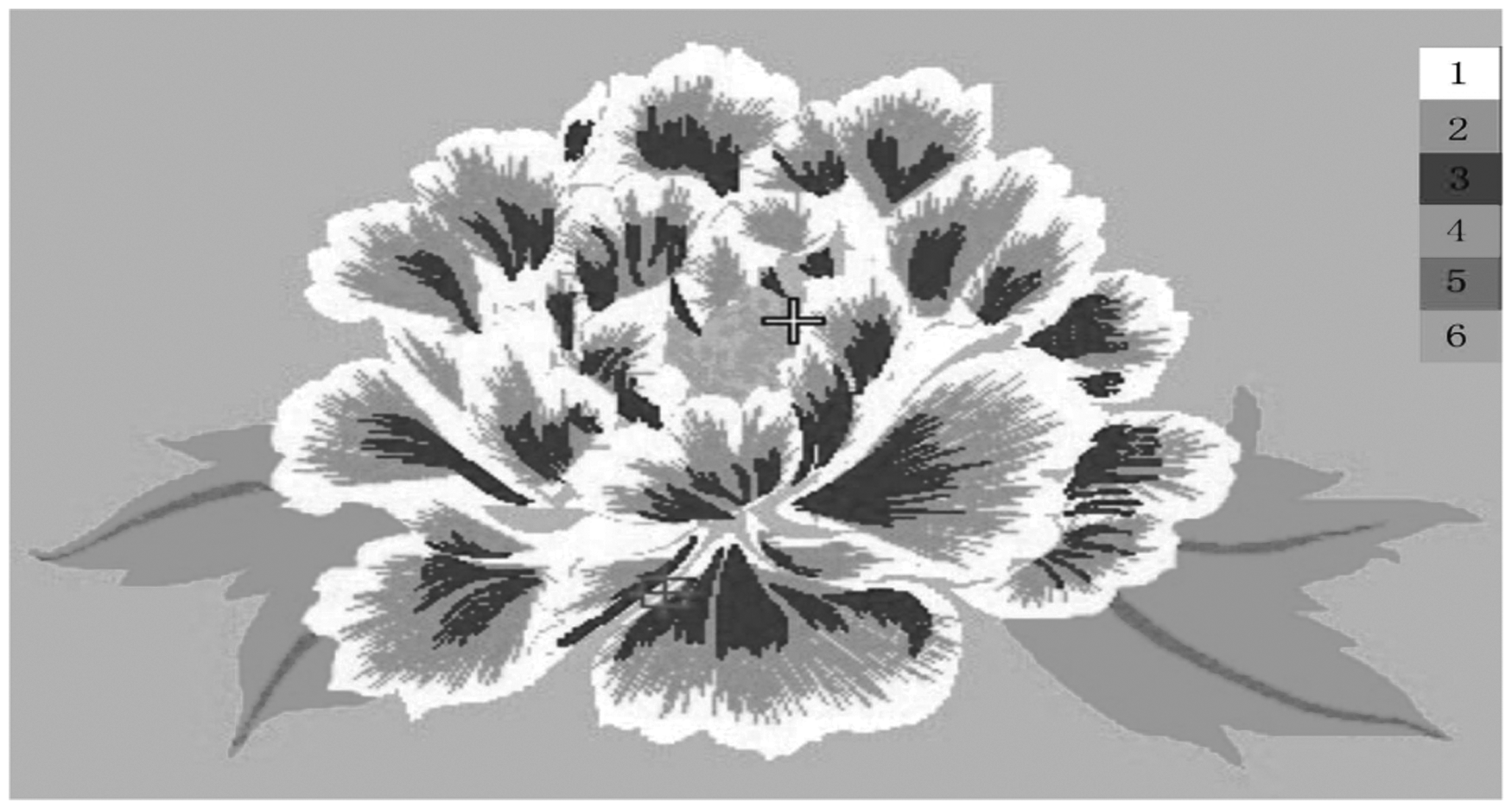
Each layer of the luminous pattern of the peony uses different stitches in the process of embroidery plate-making. It was found that different objects need different types of stitches according to the description of object properties in Table 1. Figure 4 shows that the pattern has six layers. In Figure 6(a), the stitch in layer 1 uses a flat pack needle and the object attribute of the stitch is set as automatic segmentation. In addition, stitch spacing is set to 0.4 mm, and 7.0 mm for stitch length. In Figure 6(c), layer 2 uses a serrated needle that creates a nice shadow effect for layer 1. Still, stitch spacing is set to 0.5 mm, and 7.5 mm for the border range of drop needles. The uneven degree of sidebar 1 in Figure 6(c) is set to 2, which means the value between 1 and 10 represents the extent of requirement for the serrated needle. As the value of the uneven degree becomes greater, the length of stitches becomes smaller. Patterns 3, 5, and 6 in Figure 4 also use a flat bag needle, as shown in Figure 6(a). Stitch spacing of layer 3 is set to 0.6 mm, and layer 4 and layer 6 are both set to 0.4 mm. As the stitch density is set smaller, the distance becomes greater. Layer 4 is shown as the outline of a large irregular shape. It uses a tatami needle, as shown in Figure 6(b), and the stitch spacing is set to 0.4 mm and the deviation ratios A and B are both 0.38. The needle structure and property of each layer are shown in Figure 6.
Stitch structure of the luminous peony in the Wilcom 9.0 plate system: (a) flat pack needle; (b) tatami needle; (c) serrated needle.
Long afterglow luminous effect and luminescence mechanism
With the help of the computer-aided embroidery machine, the needlework of the luminous fabric of the peony is implemented by luminous threads and polyester threads. Figure 7 shows the light superimposed effect of luminous threads in the absence of light. As can be seen from Figure 7, luminous threads with different colors emit different types of glows at night. White luminous fiber emits green light, red luminous fiber emits yellow light, and crimson ordinary embroidery threads cannot emit any light. Therefore, due to the fact that these ordinary embroidery threads are needled on two luminous layers, peony petals in the pattern show the hollow effect. The fabric is gorgeous in the darkness as an extra layer with color ranging includes green, yellow, and black.
Light overlay effect of luminous fiber embroidered fabric at night: (1) white petal layer; (2) pink petal layer; (3) crimson petal layer.
The source of light emission of luminous fiber embroidered fabric comes from Eu2+ ion activated strontium aluminate phosphors in the luminous fiber. The rare earth ion has an unfilled and external shielded 4f 5d electronic configuration, of which the 5d electron lies in the external layer in a naked and unshielded state. Figure 8 shows the luminescence mechanism of the luminous fiber. As shown in Figure 8, the luminescence mechanism of the luminous fiber is a phenomenon of jumping and restoring of the electron between different energy levels. When the lattice temperature of rare earth luminescent materials rises, these materials begin to perk up under the illumination condition.
20
The splitting of the energy level is strongly affected by the crystal field, and the 4f electron is allowed to be freely configured on seven 4f orbits. Then, electrons that exist in 4f orbits of the Eu2+ ion with a naked and unshielded state assimilate the energy and transit to a higher energy level. Because of the energy imbalance, electrons in the excited state return to the ground state and release the energy, then the fiber emits lighting.
21
Luminescence mechanism of the luminous fiber.
Afterglow intensity test of luminous fiber embroidered fabric
Effect of superposition of stitches on afterglow intensity of the fabric
Contrast test of the afterglow intensity for the samples

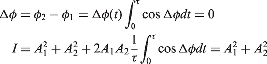
In the experiment, light intensity is the sum of two columns of light intensity. Hence, the afterglow intensity in the superimposed part is marked as “I” and can be defined as follows:
17
Effect of stitch type on the afterglow intensity of the fabric
In this experiment, samples 4–6 are made of luminous threads with the same stitch spacing, but in three different stitch types: flat pack needle, tatami needle, and serrated needle. All of these are kept consistent with the stitch types in Figures 6(a)–(c). Figure 9 shows the afterglow intensity comparison of the fabrics with different stitch types, and records their attenuation conditions within a duration time of 300 seconds. There exist the decay curves of these three types of stitch. When the afterglow time increases, these three kinds of stitch show a downward trend. The afterglow intensity of the serrated needle is lower than that of the other two stitches. The order of afterglow intensity is as follows: tatami needle > flat pack needle > serrated needle. The different afterglow intensity of sample is related to the total number of stitches. In the process of plate making, the total number of stitches for the tatami needle is 1678, 909 for the flat pack needle, and 873 for the serrated needle. It is well known that a larger total number of stitches has a higher content of rare earth aluminate strontium because the fabric is made by rare earth luminous fibers. Thus, high illumination intensity provides enough energy, and the afterglow intensity increases.
The afterglow decay curve of the fabrics with different stitch types.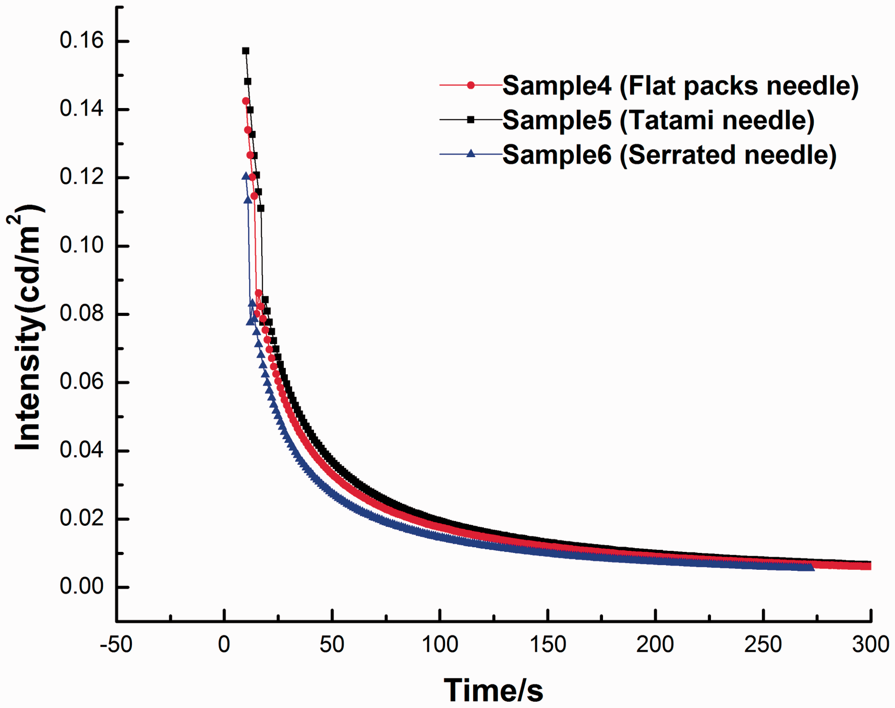
Effect of stitch spacing on the afterglow intensity of fabric
For samples 7–9, the fabrics have the same stitch type, but different stitch spacing. Specifically, 0.4 mm for sample 7, 0.5 mm for sample 8, and 0.6 mm for sample 9. Figure 10 compares the stitch spacing of these three samples, and also records their attenuation conditions within a duration time of 300 seconds. It shows that the afterglow intensity of the samples is different because of different stitch spacing. Moreover, afterglow intensity of these three samples decreases gradually and then remains stable after about 200 seconds. Sample 7 has the maximum initial intensity, and sample 9 has the minimum initial intensity. In addition, with the increase of stitch spacing, the afterglow intensity of these three samples decreases.
The afterglow decay curve of the fabrics with different stitch spacing.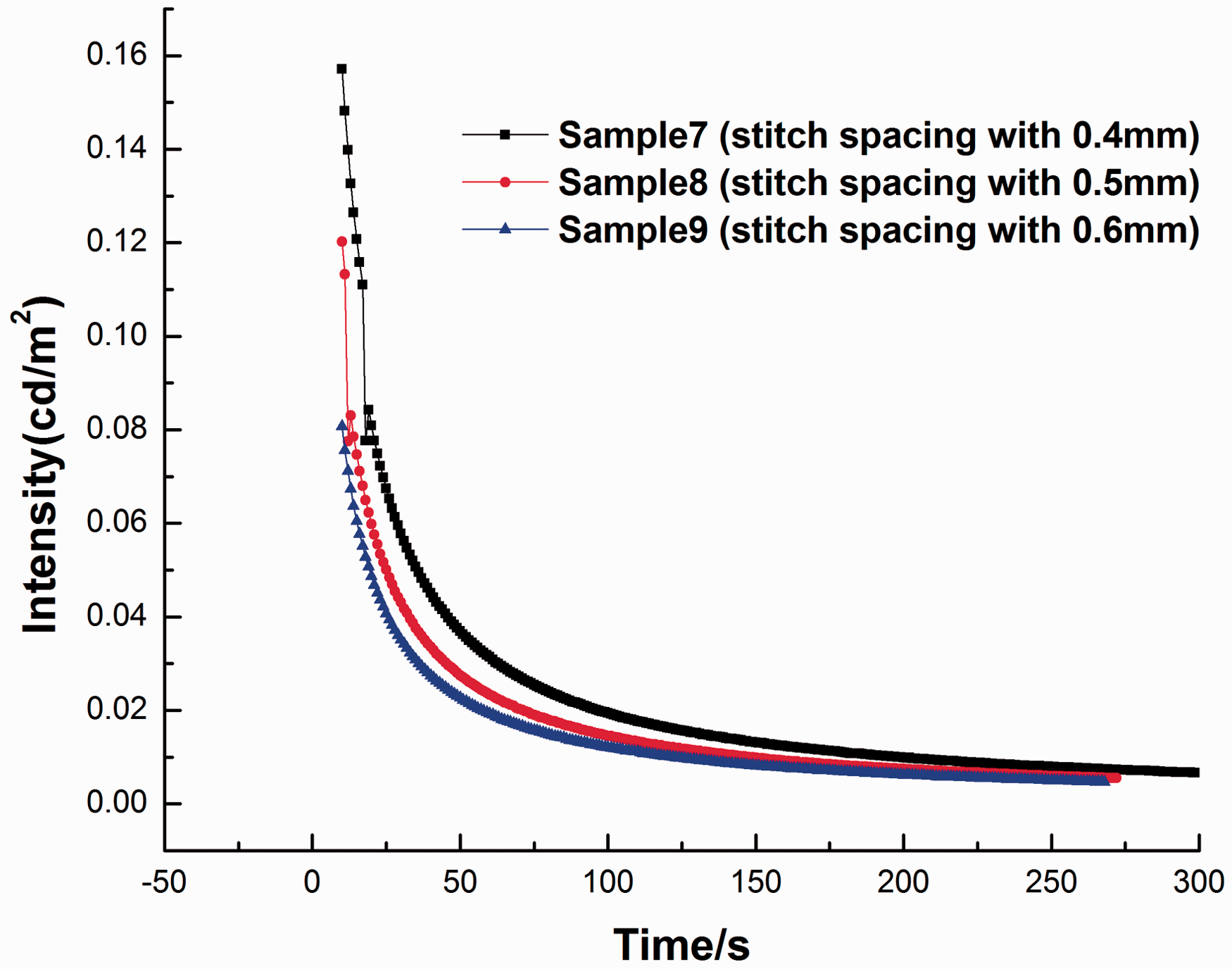
The main reason that accounts for the result is that with the increase of stitch spacing, the stitch density of the fabrics decreases. This is due to the fact that with the increase of spectral transmittance of the fabric, Eu2+ ion activated strontium aluminate phosphors (SrAl204: Eu2 +, Dy3 +) in the fabrics can therefore absorb little incident light. For this reason, strontium aluminate absorbs fewer photons that are excited by the light with larger stitch spacing, and then generates few photon transmissions. Moreover, we deduce that some of the photons inevitably pass through the fabrics and therefore the afterglow intensity decreases. For this reason, it is better to prepare the luminous embroidered fabric with relatively smaller stitch spacing.
Conclusion
By designing different stitch types, stitch spacing and superposition of stitches in multiple layers, and combining the luminous fiber with ordinary fiber using a computer-aided embroidery machine, luminous fiber embroidered fabric with high afterglow intensity and long afterglow time can be made.
The design method of luminous fiber embroidered fabric is developed using the technology of stitch superposition. The designed layers of the fabric display a long afterglow effect under the control of the volume of rare earth aluminate luminescent materials in luminous fiber.
Stitch type, stitch spacing, and superposition of stitches have a great influence on the afterglow performance of the fabric. In the plate-making process, different luminous fibers with the superposition method affect afterglow intensity of the fabric at night. As the stitch spacing increases, the afterglow intensity of the fabric decreases. The fabric with the tatami needle has the maximum afterglow intensity compared with the other two stitches.
The intensity of the fabric with superposition of two different layers is 1.122 cd/m2, but for a single layer is below 1 cd/m2 in the experiment. It is concluded that the designed fabric with the superposition method has higher afterglow luminance than the non-superposition method. The minimum brightness that can be seen by the human eye is 3 × 10⁻⁴cd/m2, which proves that the above design method can be used for the preparation of luminous fiber embroidered fabric. The fabrics that possess persistent luminescence can emit in the visible range several hours after ceasing the irradiation. Therefore, the designed fabric not only can be applied to the garment industry, home textiles, decoration, and other fields, but also can provide a theoretical basis for improving the afterglow performance and even the application of luminous fibers in the future.
Footnotes
Declaration of Conflicting Interests
The authors declared no potential conflicts of interest with respect to the research, authorship, and/or publication of this article.
Funding
The authors disclosed receipt of the following financial support for the research, authorship, and/or publication of this article: This work was supported by the Ministry of Education Innovation Team (NO. IRT1135) and the College Industrialization Project of Jiangsu Province (NO. JH10-29).