



Abstract
The most important performance requirement of a traverse mechanism is that the thickness of the silk package formed by the traverse mechanism is uniform or has little variation in the centre. To realize this requirement and overcome the structural shortcomings of traditional traverse mechanisms, a new kind of traverse mechanism is proposed in this paper. The proposed mechanism is characterized by a non-circular gear drive formed by an eccentric gear and a conjugated two-lobed non-circular gear. Its kinematic model is deduced, together with a calculation model for the formed shape of the silk package cross-section. Both of these models contain the influence caused by the shift motion. Based on these two models, a computer-aided analysis program for the traverse mechanism, using MATLAB, is developed and the influences of the mechanical parameters on the formed shape of the silk package are analyzed. Furthermore, the mechanical parameters based on the new traverse mechanism give a better performance when compared with the traditional mechanism.
Keywords
Silk reeling1–4 is the process of collectively unwinding filaments from a group of cooked cocoons in a warm water bath and winding the resultant silk thread onto a reel. This process can be achieved using a silk reeling machine.5,6 The traverse mechanism is the core part of the silk reeling machine, which causes the silk thread to wind onto the reel through the reciprocating motion of a traverse rod, and forms the silk package through a reciprocating action. In order to ensure that the silk package can form in a stable fashion, unwind easily, dry easily, and soak equally through the package, the movement of the traverse rod should be designed to have a uniform motion, or at least approximate uniform motion, to make the thickness of the silk package along the axial direction of the reel uniform, or to have only a small variation in the centre. The movement should comprise a stroke motion and a shift motion, which are together called the composite motion. As shown in Figure 1, the traverse rod carries the silk thread to reciprocate along the path Composite motion of traverse rod: (a) stroke motion; (b) shift motion.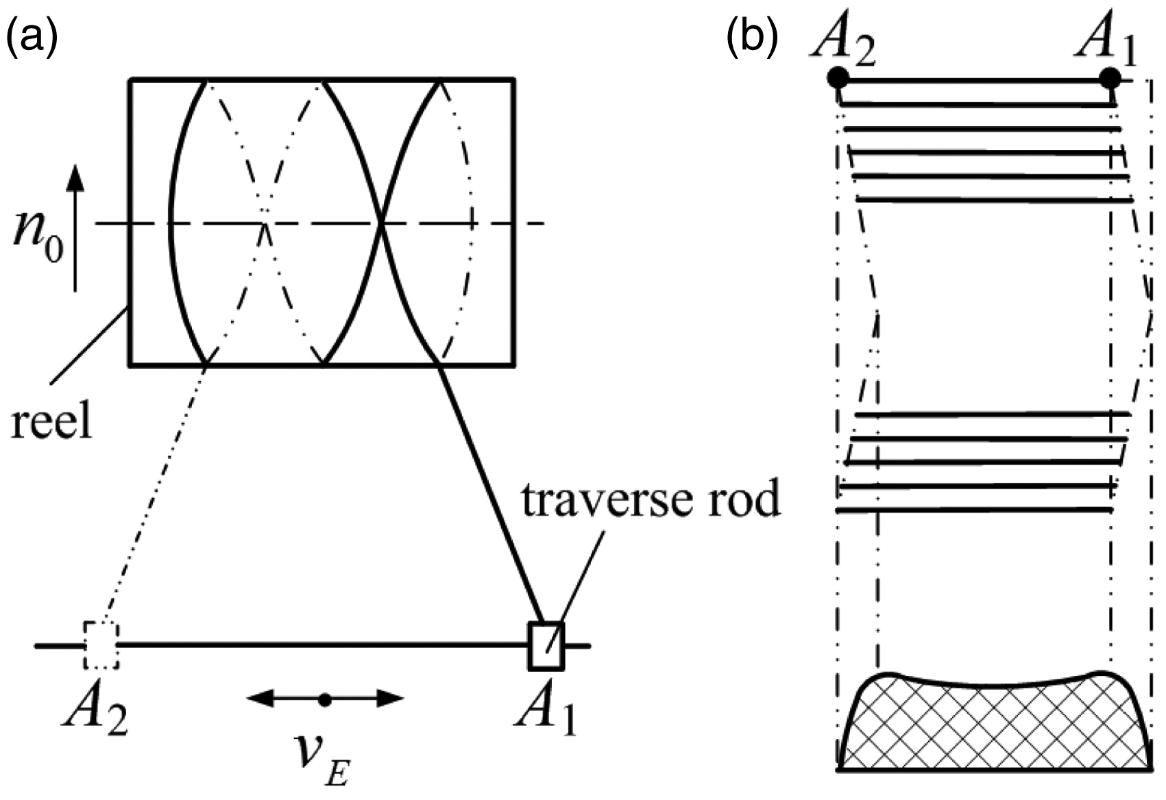
There are two types of traverse mechanism.7–9 In one type both the stroke motion and shift motion are driven by cylindrical cams. In this mechanism the traverse rod can realize a uniform motion by changing the profile of the cylindrical cam. But if the speed is uniform, the shock during the process of reversing will be too great to suit high-speed silk reeling. In the other type of traverse mechanism the stroke motion is driven by a combination of a epicyclical gear train with a crank–link–slider linkage, and the shift motion is driven by a grooved cam. The epicyclical gear train is composed of a pair of eccentric gears and a pair of cylindrical gears with 1:2 gear ratio, and the crank is combined with the driven cylindrical gear. Powered by transmission through the eccentric gear pair, the crank rotates at a changing angular speed, which reduces the variation in the speed of the slider (traverse rod). At the same time, power is transmitted through cylindrical gears with 1:2 gear ratio; the speed of the traverse rod when it moves outwards is the same as when it returns, which is good for forming a silk package with a uniform network structure. This kind of traverse mechanism moves steadily because of the use of gears, so it suits high-speed silk reeling. But the variation in the speed of the traverse rod is large, which makes the silk package form with a concavity in the centre and a convexity on each side, which is not good for stability and for increasing the thickness of the silk package. In addition, there are also two other shortcomings. One is that this kind of traverse mechanism is driven by two-stage gears, so its power transmission line is long and the structure is complex. The other is that the gear backlash of an eccentric gear pair is great when they mesh,10,11 which affects the stability of motion of the traverse rod.
The second type of mechanism, as mentioned above, is widely used at present. This paper proposes a new traverse mechanism aimed at its shortcomings. Different from the traditional mechanism, the new mechanism uses a non-circular gear drive formed by an eccentric gear and a conjugated non-circular gear. When the driving eccentric gear rotates at a constant speed, the driven conjugated non-circular gear rotates at a changing angular speed without gear backlash. 12 Litvin et al.12,13 designed and made a non-circular gear drive. Mundo 14 and Ottaviano et al. 15 proposed the application of non-circular gears for speed variation. Go-Hong Yu et al. 16 extended the use of this non-circular gear drive, designing a new transplanting mechanism that is the core part of a rice transplanter. By applying this non-circular gear drive, the kinematic characteristics of the transplanting mechanism better meets the agricultural technology. Therefore this paper uses this non-circular gear drive to improve the kinematic characteristics of the traverse rod. At the same time, aiming at the shortcomings brought about by the use of two-stage gears, the conjugated non-circular gear used in this paper is two-lobed to reduce the numbers of gears.
In order to analyze the movement of the traverse rod, Min-de Shen and Rong-gen Ling 9 and Tai Kang 17 deduced a kinematic model of the traverse mechanism. In order to estimate the performance of the traverse mechanism, Tai Kang 17 and Reng-Su Song 18 deduced a calculation model for the formed shape of the silk package cross-section. But these models ignore the influences caused by the shift motion, so the real movement of the traverse rod cannot be obtained by using these models. In this paper, the kinematic model of a new traverse mechanism is deduced, including both the stroke motion and the shift motion. A calculation model for the formed shape of the silk package cross-section is also deduced. In addition, a computer-aided analysis program for the traverse mechanism based on MATLAB (R2010b, MathWorks, Natick, Massachusetts, U.S.A) is developed. By taking advantage of this program, the influences of the mechanical parameters on the formed shape of the silk package are analyzed, and the mechanical parameters for approximating uniform motion of the traverse rod are obtained. Finally, a comparison is made between the shapes formed by the traditional traverse mechanism and the new mechanism.
Structure of traverse mechanism with an eccentric gear and a conjugated two-lobed non-circular gear
The traverse mechanism with an eccentric gear and a conjugated two-lobed non-circular gear is shown in Figure 2. The power from the engine causes shaft 1 to rotate. This is then divided into three parts. First, chain wheels 2 and 3 and cylindrical gears 6 and 4 cause reel 5 to rotate. Secondly, traverse rod 16 moves back and forth through bevel gears 9 and 10, a non-circular gear drive and a crank–link–slider linkage, forming the stroke motion of the traverse rod. The non-circular gear drive is composed of the eccentric gear 17 and the conjugated two-lobed non-circular gear 11. The crank–link–slider linkage is composed of crank 13, link 12, rocker 14, link 15, and traverse rod 16. Thirdly, box 18 oscillates through worm gear 7, worm wheel 8, conjugate cam 20 and the oscillating roller follower 19. The oscillating motion of box 18 makes the starting position of traverse rod 16 shift every time it reciprocates, forming the shift motion. Stroke motion and shift motion comprise the motion of traverse rod 16.
Kinematic schematic of traverse mechanism with an eccentric gear and a conjugated two-lobed non-circular gear. (a) Top view; (b) front view.
For the crank–link–slider linkage in this new traverse mechanism, if crank 13 rotates at a constant speed, traverse rod 16 will move quickly in the middle of its motion, and slowly at each side. In order to reduce the change in speed of the traverse rod, crank 13 should move quickly when the traverse rod is on each side and move slowly when it is in the middle. For this purpose, the conjugated non-circular gear has two lobes. While the driving eccentric gear rotates twice, the driven conjugated non-circular gear rotates once. The speed of the conjugated two-lobed non-circular gear changes from slow to fast and from fast to slow four times in one cycle, which exactly corresponds with the speed changes of the traverse rod in one reciprocating action. Therefore the traverse rod could realize approximately uniform motion by choosing appropriate parameters for the eccentric gear and the conjugated two-lobed non-circular gear. Meanwhile, by using a conjugated two-lobed non-circular gear, the new traverse mechanism has one less pair of gears when compared with the traditional one, which makes the structure more compact and the transmission efficiency higher. In this new traverse mechanism, the conjugate cam drives the box back and forth to realize the shift motion. The conjugate cam has little wear when compared with the grooved cam used in the traditional traverse mechanism, and it is also easy to machine.
Kinematic model of the traverse mechanism with an eccentric gear and a conjugated two-lobed non-circular gear
The stroke motion of the new traverse mechanism is driven by the combination of an epicyclical gear train with a crank–link–slider linkage, so the kinematic model can be divided into two parts.
Kinematic model of epicyclical gear train
Because of the traverse mechanism’s shift motion, the axis of the conjugated two-lobed non-circular gear rotates around the axis of the eccentric gear. Therefore, the non-circular gear drive is an epicyclical gear train. To build the kinematic model of this epicyclical gear train, a kinematic model of a non-circular gear drive with fixed axes is built first.
Non-circular gear drive with fixed axes
When the axes of the gears are fixed, the eccentric gear is the driving gear and the conjugated two-lobed non-circular gear is the driven gear, as shown in Figure 3.
Conjugation of an eccentric gear with a two-lobed non-circular gear.
The centrode of the eccentric gear is represented by12,13




The centrode of the conjugated non-circular gear will be a closed curve if the following equation is observed
12



In function F(a), a is the variable. F(a) is an absolute value function, so when F(a) = 0, the value of a is the minimum of this function. In this way, the solution of a is to find the minimum of function F(a). Optimization is an efficient method for finding the maximum or minimum of a function.
19
In this paper, the golden section search optimization method
19
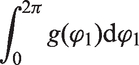
is used to find the minimum of function F(a). During the process of optimization, the calculation of the integral

Non-circular gear drive without fixed axes
When the axes of the gears are not fixed, the non-circular gear drive becomes an epicyclical gear train, as shown in Figure 4.
Epicyclical gear train with an eccentric gear and a two-lobed non-circular gear.
For this epicyclical gear train, the gear ratio function of its converted gear train


Both ends of equation (9) are integrated for time t, and can then be written as


Kinematic model of crank–link–slider linkage
The crank–link–slider linkage shown in Figure 5 is composed of a four-bar linkage and a slider–crank linkage. An X,Y Cartesian coordinate system fixed on the eccentric gear and with its origin at the rotation center O1 is set up. In this case, Combination of the epicyclical gear train with the crank–link–slider linkage.


If equation (12) is turned into analytical form, it can be written as

The unknown parameters


If equation (13) is turned into analytical form, it can be written as

From equation (17), the unknown parameter

From equation (18),

Calculation model for the shape of the silk package cross-section
The most important performance requirement of the traverse mechanism is that the thickness of the silk package formed by the traverse mechanism is uniform or has small variation in the centre. In order to estimate the performance of the traverse mechanism, a calculation model for the shape formed through the silk package cross-section should be built. The main parameter that affects the shape of the silk package is the winding angle γ.
9
The winding angle γ of the silk thread is represented by

If an infinitesimal section of the silk package is taken off, the amount of silk per unit axial length ξ in the section is directly proportional to the number of silk threads, N, and is inversely proportional to the sine of the winding angle γ.
17
It can be expressed as

From equation (21) it can be found that, in the case of the same number of silk threads, if two adjacent silk layers are equal in winding angle, the silk thread will have a very good network distribution, uniform density, and a good shape. So when the number of silk threads is the same, the changes in the amount of silk can be expressed as the curve of a specific value
Computer-aided analysis program and influence analysis of parameters on the formed shape
Writing of computer-aided analysis program
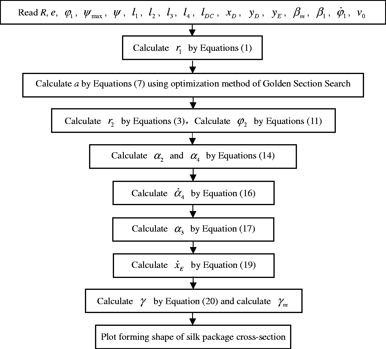
The mechanical parameters of the traverse mechanism affect the kinematic characteristics of the traverse rod and the formed shape of the silk package. In order to analyze the effect of these parameters easily, a computer-aided analysis program with a user-friendly graphical user interface based on MATLAB was developed, as shown in Figure 6. The flowchart of the numerical algorithm for the program is given in Figure 7.
Computer-aided analysis program for the traverse mechanism. Flowchart of the numerical algorithm for the program.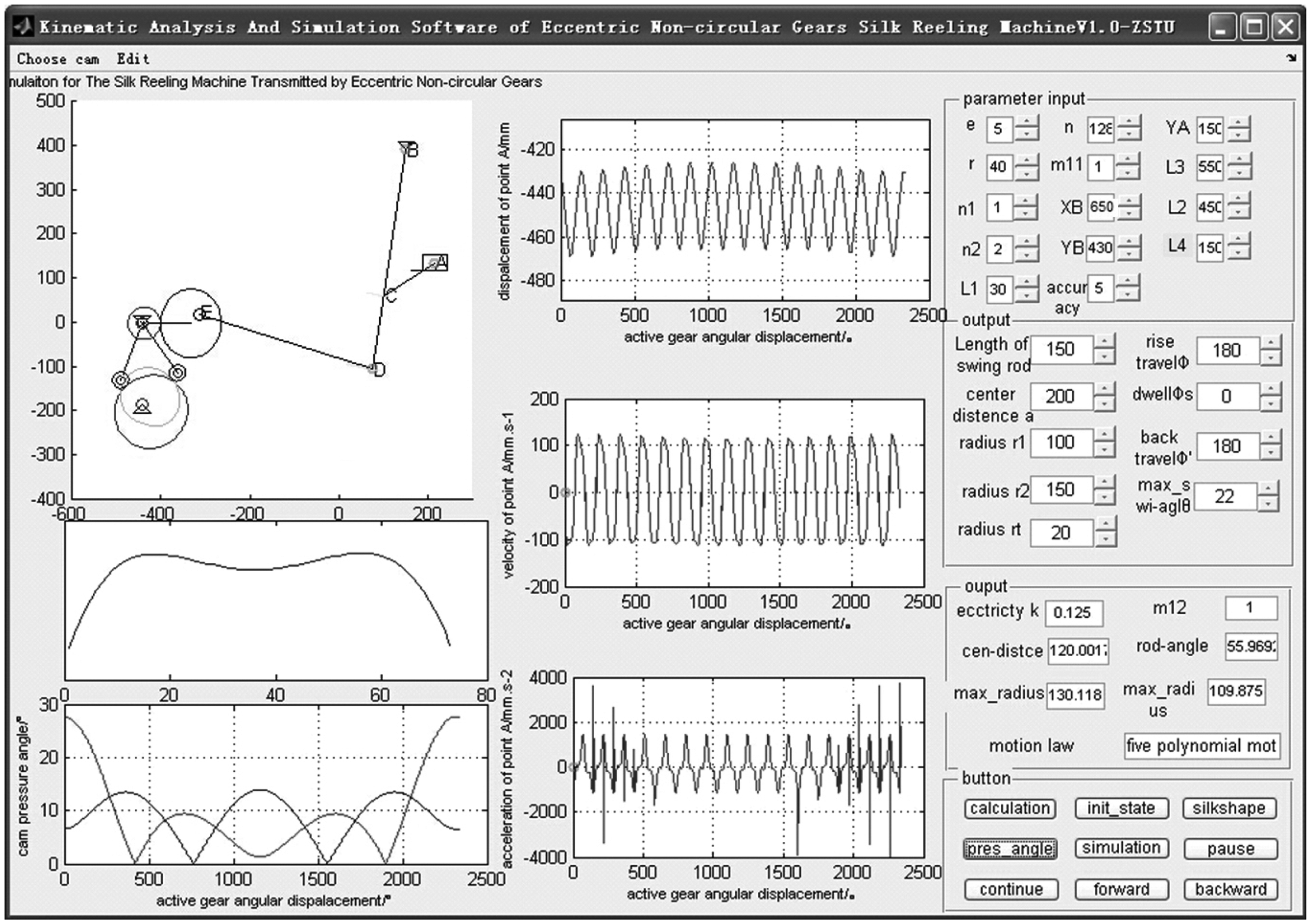
After inputting mechanical parameters such as the eccentricity and radius of the eccentric circle, the maximum angle of rotation of the planet carrier box (Figure 2, part 18), the length of every link and crank in the crank–link–slider linkage, etc, the program can automatically calculate the displacement, velocity, and acceleration of the traverse rod, and draw the corresponding kinematic curves. This program can also conduct motion simulation for the traverse mechanism and draw the formed shape of the silk package cross-section.
Influence analysis of mechanical parameters on the formed shape of the silk package cross-section
In order to choose an appropriate non-circular gear drive and conjugate cam for the new traverse mechanism, the influence of the mechanical parameters on the formed shape are studied in this section. The influence analysis is carried out by changing the eccentricity e and the maximum angle of rotation of the planet carrier,

Design parameters for traverse mechanism

Influence analysis of e on the formed shape
The formed shapes of the silk package cross-section for various eccentricities e are shown in Figure 8. It can be seen that, with the increase of the eccentricity, the variation in thickness in the centre of the silk package changes initially from large to small, and then it changes from small to large. This means that an eccentricity that is too small or too large will result in a poorly formed shape.
Formed shape of silk package cross-section for various eccentricities (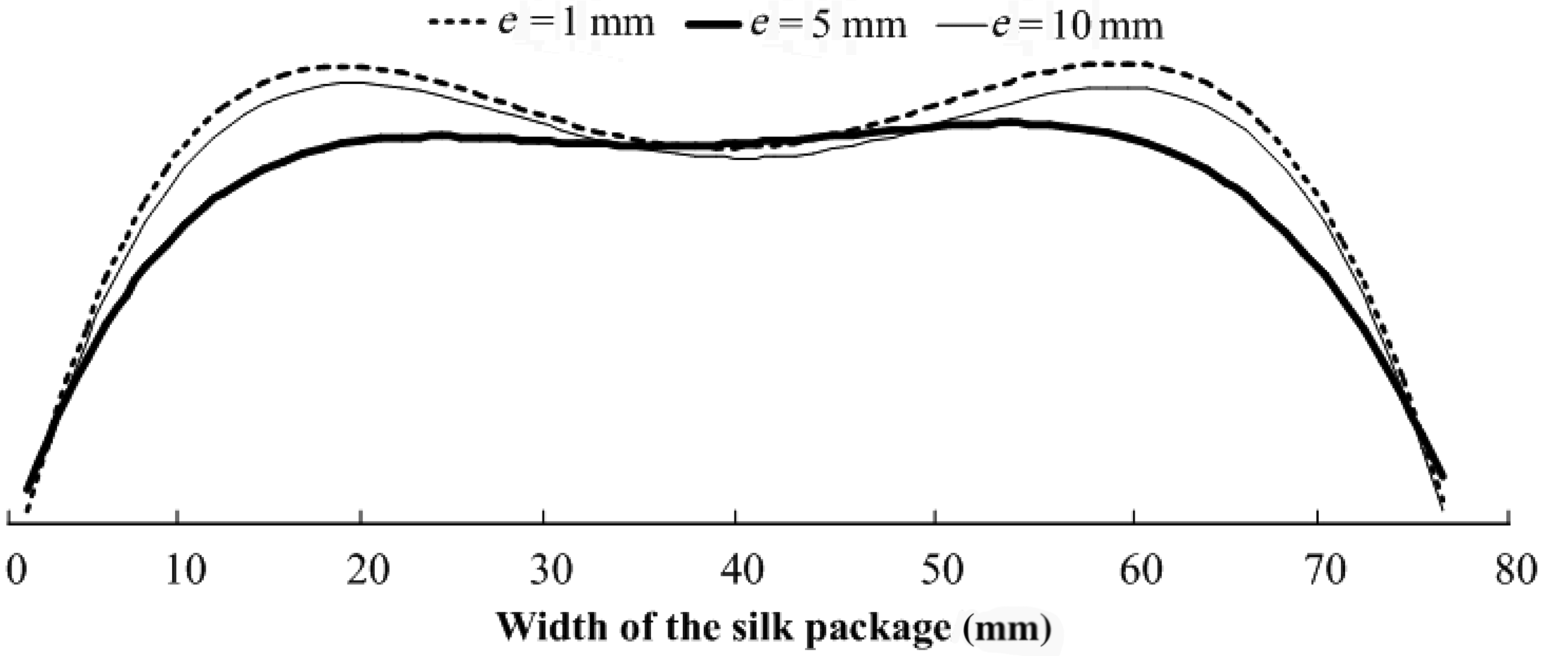
Influence analysis of
on the formed shape
The formed shapes of the silk package cross-section for various maximum angles of rotation of the planet carrier Formed shape of silk package cross-section for various maximum angles of rotation of the planet carrier (e = 5 mm).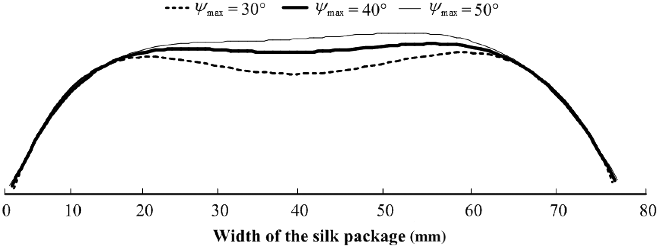
Comparison of the formed shape between the new traverse mechanism and the traditional one
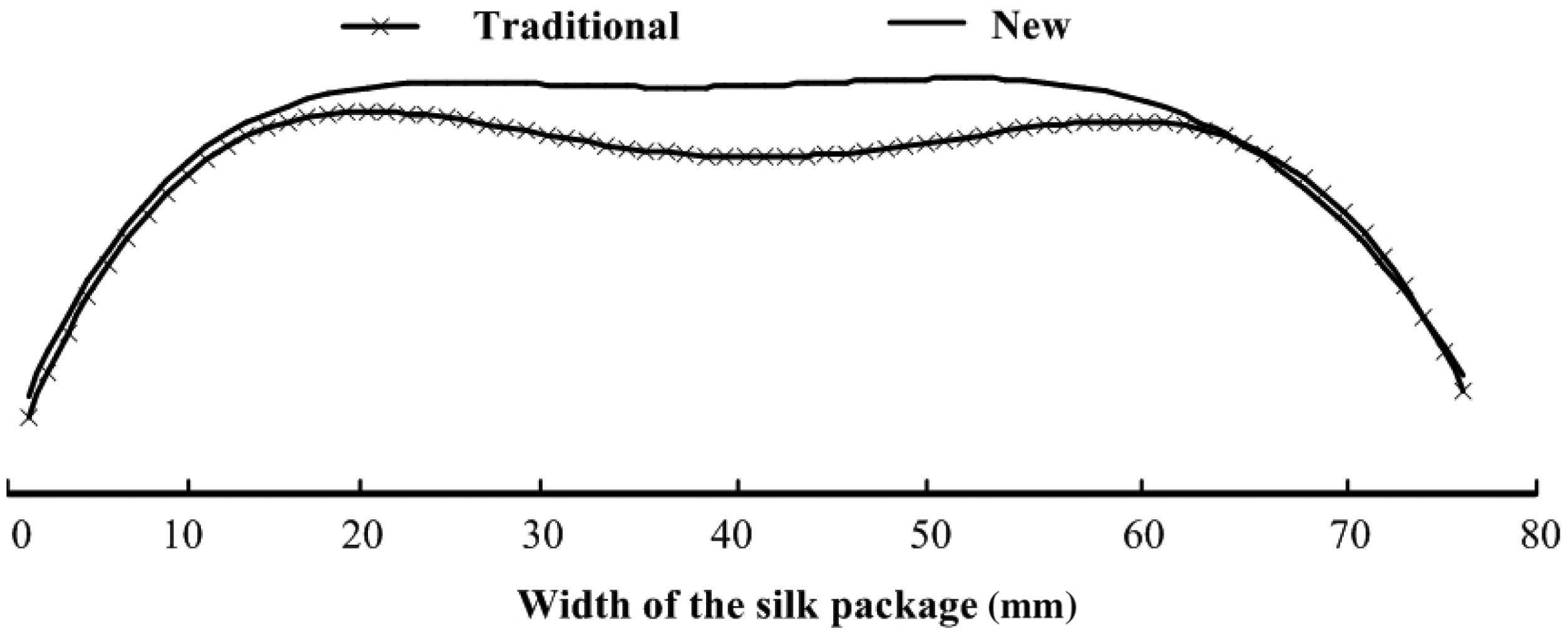
When e = 5 mm and Velocity of traverse rod in one cycle. Comparison of the formed shape between the new traverse mechanism and the traditional one.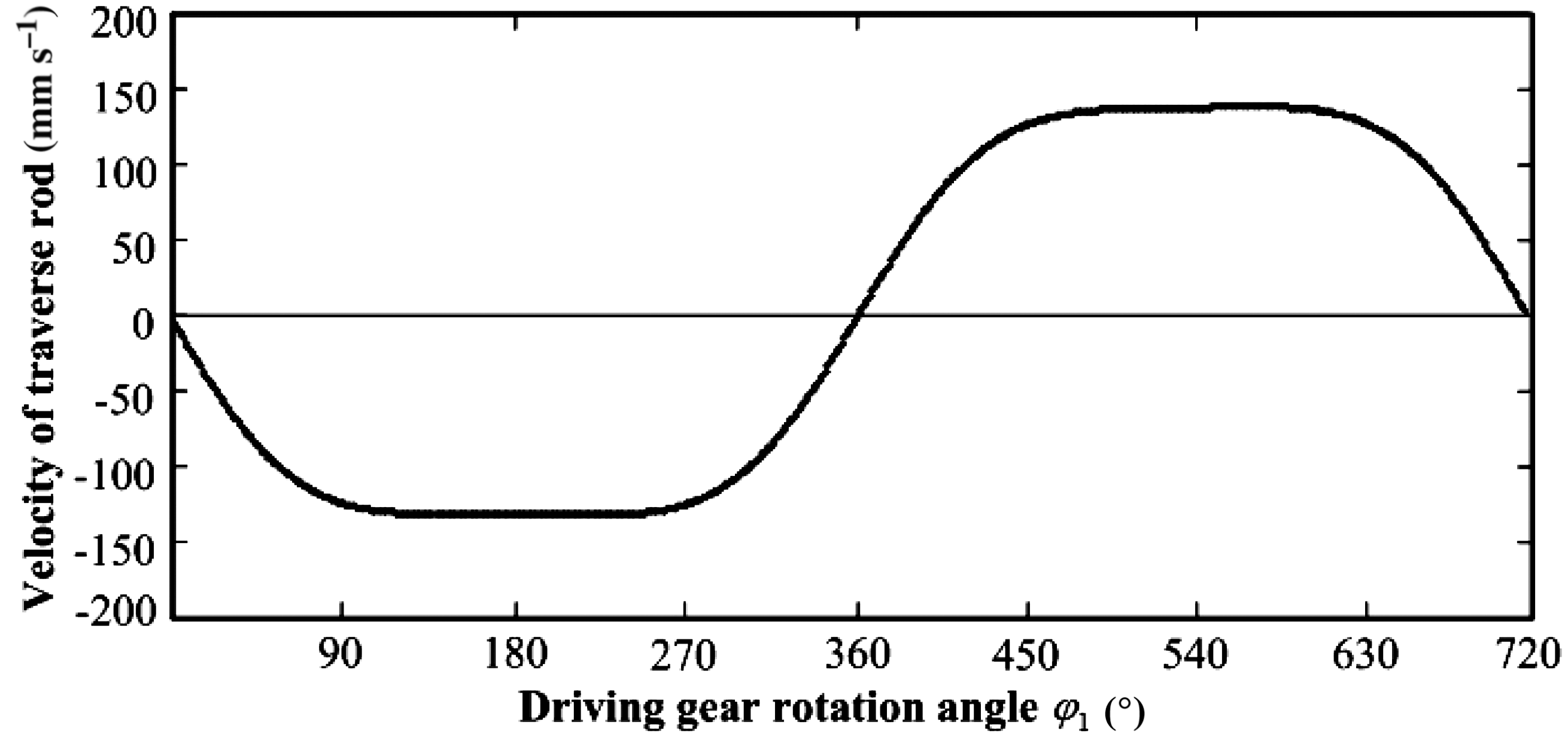
Conclusions
In this paper, a new kind of traverse mechanism with an eccentric gear and a conjugated two-lobed non-circular gear is proposed. By using a conjugated two-lobed non-circular gear the new traverse mechanism uses one less pair of gears when compared with the traditional one, which makes the structure more compact. The influence of the eccentricity and the maximum angle of rotation of the planet carrier on the formed shape of the silk package have been studied based on the kinematic model of the new mechanism and the calculation model for the formed shape of the silk package cross-section. It is shown that eccentricities that are too small or too large will result in a poorly formed shape, and the formed shape will become better with an increase of the maximum angle. Based on the influence analysis, when the eccentricity is 5 mm and the maximum angle of rotation of the planet carrier is 40°, the movement of the traverse rod approximates uniform motion with a speed of about 131 mm/s in the centre. Finally, a comparison of the formed shapes made by the traditional traverse mechanism and the new mechanism was conducted, and the results show that the new traverse mechanism has a better performance. The kinematic model of the new traverse mechanism and the calculation model for the formed shape provide a numerical approach for the design and analysis of the traverse mechanism. The new traverse mechanism proposed in this paper provides a better traverse mechanism for the silk reeling machine. In future work, we will deduce the dynamic model and the parameter optimization model for the traverse mechanism to find the optimal parameters, and then develop a test bed based on the optimal parameters to verify the working performance of the new traverse mechanism.
Footnotes
Declaration of conflicting interests
The authors declared no potential conflicts of interest with respect to the research, authorship and/or publication of this article.
Funding
The authors disclosed receipt of the following financial support for the research, authorship, and/or publication of this article: This work was supported by National Natural Science Foundation of China (grant number 51505239), Zhejiang Provincial Natural Science Foundation of China (grant number LQ15E050003), and Natural Science Foundation of Ningbo city (grant number 2015A610099).