



Abstract
In this work, the utilization of different textile materials for manufacturing of metamaterial with the aim of controlling the signal propagation in smart textile applications is investigated. The performance of composite structures of embroidered yarn conductor transmission lines loaded with split-ring resonator geometries in felt and cotton substrates are reported. The proposed structure allows propagating or filtering the transmitted signal in the microwave frequency range. The experimental results exhibit a rejection band between 1.3 and 2.6 GHz for felt substrate and between 1.6 and 2.6 GHz for cotton substrate with stop-band levels lower than –20 dB. The presented e-textile structures are designed, electromagnetically simulated and measured. The measured results are in good agreement with three-dimensional electromagnetic simulations. The effect of bending of the e-textiles for realistic scenarios is also studied. The experimental results show that by changing the radius of bending from 10 to 65 mm, the resonance frequency is shifted up 290 and 144 MHz for cotton and felt substrates, respectively.
Electronic textiles (e-textiles) are a key component of the smart textile field for developing new wearable applications for wireless body area networks (WBANs). Such applications are being deployed in the sports, fitness, medical, health care and fashion industry sectors.1,2 For instance, wearable antennas have been recently developed in order to improve the integration of the radio frequency systems on garments and to allow radio communication.3,4 On the other hand, metamaterials (MTMs) have attracted significant attention from researchers since the beginning of the 21st century.
5
These artificial structures are usually designed to obtain controllable and inaccessible electromagnetic (EM) properties not found among natural materials. MTM transmission lines benefit from those properties and they can control the behavior of the guided signals up to a certain level. The microstrip is a typical transmission line used to transmit radio frequency signals and it is commonly fabricated using printed circuit board (PCB) technology. It consists of a strip conductor and a ground back-plane, separated by a dielectric. Its main advantages are a high compatibility with active devices and an excellent balance between cost, size and characteristic impedance control. Its main drawbacks are a low power handling capacity and high losses at high radio frequencies. The first feature could match properly with wearable applications, because low power is required for safety reasons. Concerning losses, this fact is unavoidable but, in any case, textile substrate losses are intrinsically high in comparison with PCB standard materials. The way to reduce the overall losses of the wearable system is to reduce the loss tangent of the selected fabrics and to use high-quality conductive yarns. Different kinds of MTM resonators have been investigated to achieve selective frequency responses. Among them, the split-ring resonator (SRR) is a widely proposed magnetic resonant structure.5–9 As can be observed from Figure 1, the SRR structure consists of a ring with a gap, which corresponds to an equivalent inductance (L) and capacitance (C), thus generating an equivalent LC tank. Since we can control and optimize the design of microstrip components by using SRRs, it is theoretically feasible to implement such structures in textile substrates in order to optimize the performance of wearable or e-textile devices, whose main requirements are flexibility, lightweight, low profile and compactness.
Split-ring resonator and its equivalent circuit model.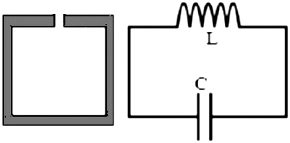
Embroidery machines enhance the integration of e-textile substrates, because of the repeatability of digital layout patterns. Therefore, mass production of garments and customized designs in terms of thread distribution with a resolution in the order of <1 mm can be achieved. 10 Textile MTMs have been directly reported in the literature for antenna applications. 11 Textiles have also been used in composite polymer fiber fabrics, 12 and copper SRRs have been used as a narrow-band solution to reduce EM radiation 13 and for passive ultra-high frequency (UHF) radio-frequency identification (RFID) tags. 14 In addition, textile substrates have been used in wearable antenna applied to WBANs.15–19 However, wearable e-textiles have some limitations that must be addressed. One of them is the effect of the electrical impact of the human body, since biological tissues make up a lossy medium. In addition, the body shape changes the electrical performance of the prototypes due to bending and this issue must be addressed. The impact of the e-textile on the body is usually taken into account by means of the specific absorption rate (SAR). Nevertheless, in full grounded structures such as microstrips, this effect could be neglected. Another current limitation of the e-textiles corresponds to washability20,21 and durability of the samples, and work is in progress by several research groups to address this issue.
In this work the effect of MTMs based on an embroidered transmission line loaded with SRRs on felt and cotton substrates are analyzed, modeled and measured. In particular, the filtering effect of the textile SRRs is studied. The main idea of the design is to implement embroidered SRR particles in order to filter and control the signal propagation in the UHF range along the e-textile. Adjustment of the geometrical positioning of the geometrical pattern threads allows tunable resonance frequencies to be achieved. The main advantage of these structures in comparison with regular transmission line filters is the intrinsic reduction of the dimensions of the filter due to the subwavelength particles used (SRR). Moreover, since we are working with embroidery patterns it is necessary to achieve simple geometries and this is the case with these types of structures. The proposed prototypes have been simulated by means of the commercial full three-dimensional (3D) EM CST Microwave Studio 2018 software. The proposed prototypes have been subsequently fabricated and analyzed in bandwidths between 1.2 and 3 GHz in a free space environment. For the measurement of the insertion losses (S21) and return losses (S11), an N9916A FieldFox (Keysight) vector network analyzer has been used. The results of the proposed designs show that textile MTMs can be efficiently applied in filtering and controlling the propagation of signals operating in the WBAN relevant frequencies. Among other applications, the presented e-textiles can be considered in the development of wearable sensors and RFID tags.
The main novelty of the work is to combine full embroidered e-textile designs including MTM particles by achieving significant frequency rejection bands in e-textiles. Moreover, the bending effects have been addressed in order to evaluate the impact in several realistic body shape scenarios.
E-textile metamaterial design and equivalent circuit model
There are several structure geometries available for SRRs, such as square-shaped, omega shaped, U-shaped, etc. In this work, square-shaped SRRs have been selected in order to enhance the coupling between the host line and the resonator itself. In addition, this geometry involves a better optimization process in terms of design and simulation. The structure of the proposed design and its relevant dimensions are depicted in Figure 2(a).
(a) Layout of the split-ring resonator (SRR)-loaded transmission lines with the relevant dimensions: l1 = 25 mm, l2 = 22 mm, g = 60 µm, S = 0.18 mm, W1 = 1.5 mm, W2 = 3.9 mm. (b) Lumped element equivalent Π-circuit model considering magnetic coupling between the line and the SRR. (c) Simplified circuit results after transformation of the series branch.
22
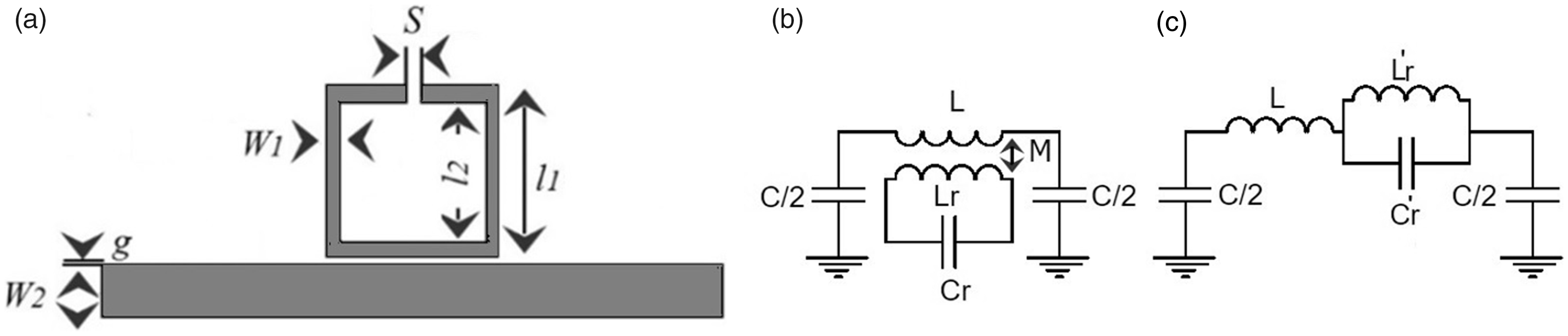
At the SRR resonance frequency, the LC tank behavior is exhibited and the guided signal is coupled to the SRR. Therefore, a stop-band effect arises and it is possible to filter the signal propagation by controlling the SRR dimensions and geometry. This effect is reflected in the lumped element equivalent circuit model, depicted in Figure 2(b). The equivalent circuit model of the series branch can be simplified as depicted in Figure 2(c).
After a tuning design process with the EM simulator, the dimensions of the proposed design are set as follows: length of the outer ring l1 = 25 mm; length of the inner ring l2 = 22 mm; host line–SRR separation g = 60 µm; gap of the SRRs = 0.18 mm; SRR width W1 = 1.5 mm; and transmission line width W2 = 3.9 mm. The conventional transmission line has been designed with a 50 Ω characteristic impedance. The transmission line is represented by a Π-circuit model and the magnetic wall concept was applied in that model, where L and C are the line inductance and capacitance, respectively, of the unit cell; Lr and Cr are the inductance and capacitance of the SRR. Finally, M accounts for the magnetic coupling between the line and the ring. To extract the parameters, the coupling between the host line and the SRR has been taking into account and the system has been modeled by means of the commercial Keysight Advanced Design System 2018 software. The electrical parameters have been extracted by means of the method reported by Hong and Lancaster. 23
Fabric substrates
Main physical properties of the fabrics studied

Polyester.
Weave fabric specification.

Appearance of the studied fabrics, scanning electron micrograph. (a) Face A (light serge) cotton. Warp direction ↑. (b) Face B (heavy sarge) cotton. Warp direction →.
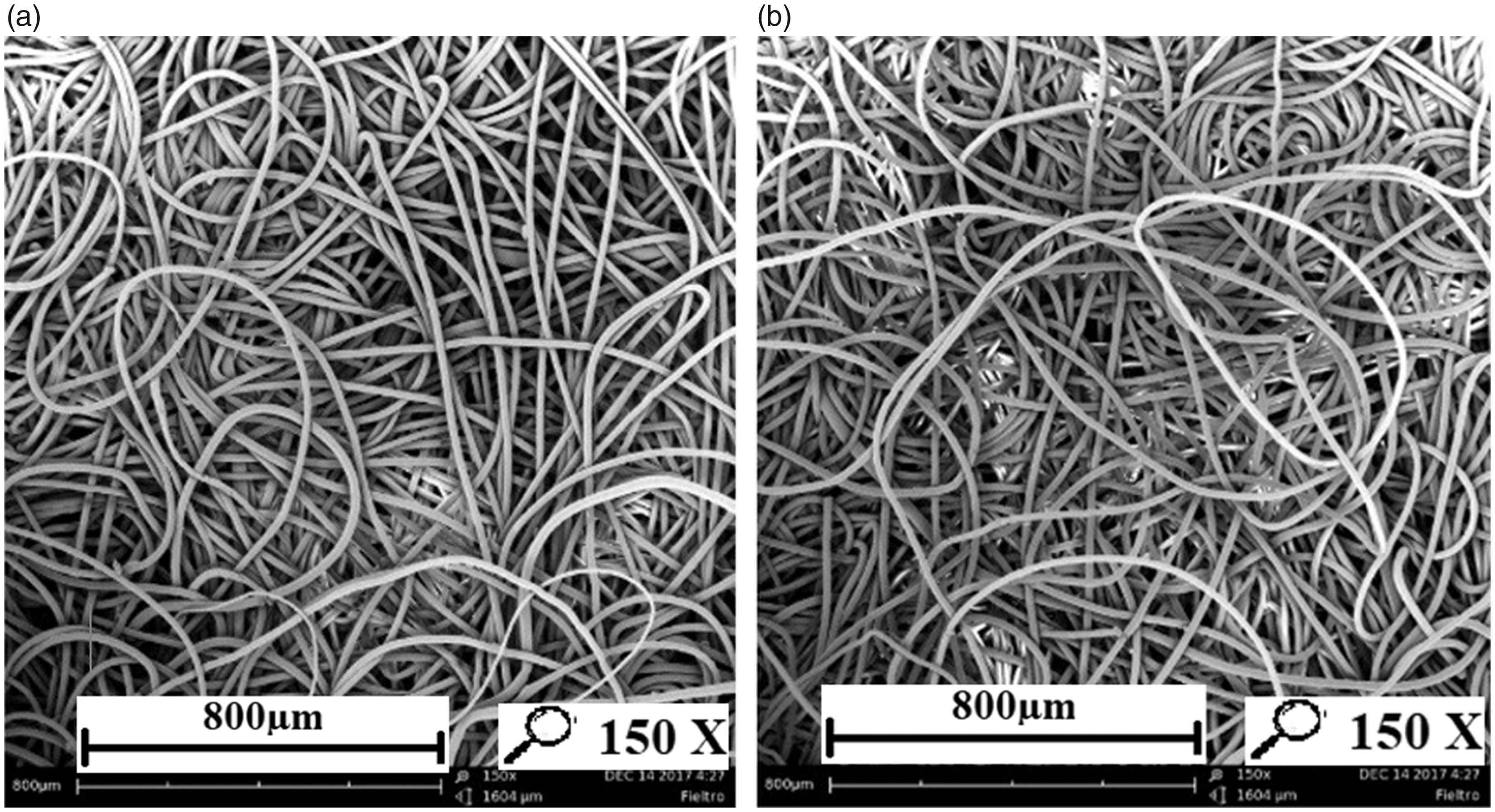
Appearance of the studied fabrics, scanning electron micrograph. (a) Face A (light serge) felt. Warp direction ↑. (b) Face B (heavy sarge) felt. Warp direction→.
Experimental details
A Singer Futura XL-550 embroidery machine was used to manufacture the prototype. The used stitch type corresponds to the ISO 4915:1991 301 standard. For the PUTs, the selected conductor yarn corresponds to the commercial Shieldex Plated Nylon 66 Yarn 117/17 dtex 2-ply and it is composed of 99% pure silver plated nylon yarn 140/17 dtex with a linear resistance <30 Ω/cm.
The conductive thread is relatively thick compared to the conventional embroidery thread, due to the mechanical restrictions of the embroidery machine. In order to optimize the fabrication, processed conductive thread has been used in the bobbin of the embroidery machine, whereas a conventional embroidery yarn has been used for the upper thread. A certain degree of tension control in the upper thread is carried out in order to increase the accuracy of the stitching geometries and patterns.
The proposed design has been embroidered with a satin pattern with 60% and 40% densities for felt and cotton, respectively. The stitch spacing corresponds to the distance between two needle penetrations on the same side of a column. The density determines the gap between stitches. For narrow columns, stitches are tight, thus requiring fewer stitches to cover the fabric. In areas with very narrow columns, less dense stitches are required because too many needle penetrations can damage the textile sample. The homogeneous layout is converted to a stitch pattern by using the Digitizer Ex software for the fabrication process. This software package is used to create the stitch pattern, which is then exported to the embroidery machine and stitched. The effect of the stitch direction and stitch density has been extensively studied and described by Seager et al. 25
The ground plane for both prototypes has been chosen as a homogeneous uniform commercial WE-CF adhesive copper sheet layer (constant thickness t = 35 µm), for simplicity. The embroidered prototype on the felt substrate is depicted in Figure 5(a).
(a) Photograph of the embroidered transmission line loaded with split-ring resonators on the felt substrate with a satin pattern (60% density). (b) S-parameter responses of the electromagnetic simulation, equivalent circuit model and measurement of the proposed design.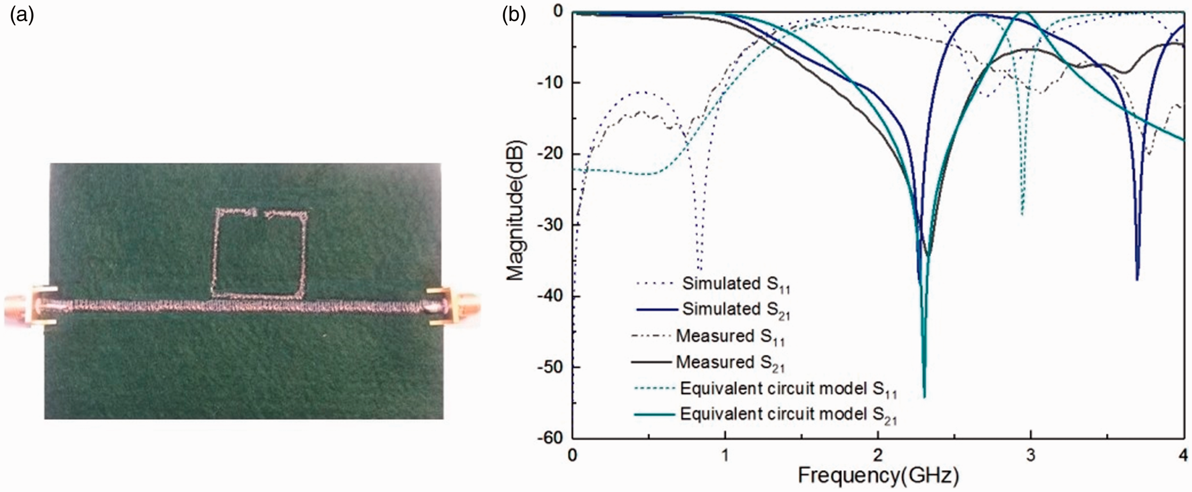
The results of simulated and equivalent circuit model analysis and measured result on felt substrate is shown in Figure 5(b). The extracted parameters of equivalent circuit model are as follows: L = 6.5 nH, C = 3 pF, Cr = 0.3 pF, Lr = 16 nH, M = 0.55 nH. A good agreement between the simulated, equivalent circuit model and the measured results is obtained. As can be observed, the proposed design exhibits a well-defined stop-band, defined at
The most interesting properties of the SRR is that the orientation and position of its gap with respect to the hosting transmission line has significant influence on the overall performance and also the number and configuration of the SRRs can change the behavior of the filter from stop-band to pass-band filter. In this work, the gap of the SRR is far from the line and the measured return loss oscillates between –0.5 and –3.5 dB and the insertion loss is
Figure 6(a) shows the embroidered proposed design on cotton substrate. The comparison of simulation and measurement results of the proposed design on the cotton substrate is shown in Figure 6(b). There is good agreement between the simulated and the measured results. The proposed design provides a stop-band between 1.6 and 2.6 GHz. The measured return loss in the rejection band oscillates between −0.5 and –2.5 dB and in the band-pass it is –3.5 dB; indeed, the insertion loss is (a) Photograph of the embroidered transmission line loaded with a split-ring resonator on cotton substrate with satin pattern (40% density). (b) S-parameter responses of the electromagnetic simulation and measurement of the proposed design.
Comparison measurement of two substrate electromagnetic properties
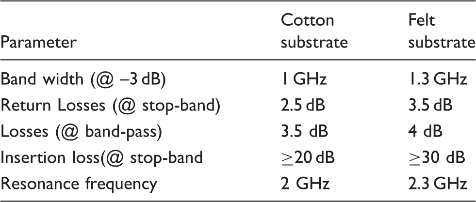
The experimental characteristic impedance for the felt substrate sample is 50 Ω, whereas for the cotton substrate sample it corresponds to 42 Ω. The slight discrepancy for the cotton case with regard to the simulated 50 Ω is due to the difficulties of measuring the two-layer case, including inhomogeneous thickness of the adhesive that was used for sticking the cotton layers. The main advantage of the felt substrate is that it provides good impedance matching and low losses compared to cotton. Also, by comparing Figures 5(b) and 6(b), it is observed that the insertion losses in the felt substrate are better than in the cotton case. The reason is that better accuracy is expected for felt due to low embroidery tension. Thus, to achieve high geometrical accuracy for felt, we have increased the embroidery density up to 60% to boost surface conductivity.
Effects of bending
In wearable systems, it is very difficult to keep the substrate in a flat configuration all the time, especially when the prototype is made of textile materials and it is frequently bent due to human body morphology and movements. Therefore, it is necessary to investigate the prototype performance characteristics under bending conditions. The S21 parameters of e-textile MTM-SRR under different bending have been measured.
It is observed that, due to bending, the equivalent length of the proposed design is changed and, hence, there are deviations in the resonance frequency. The more the prototype is bent, the more the resonant length gets reduced and so the resonant frequency gets shifted up. This fact becomes evident from the experimental observations, as shown in Figures 7(a) and (b). By changing the radius of bending from 10 to 65 mm, the resonant frequency is shifted up 290 MHz for the cotton substrate and 144 MHz for the felt case. From the S-parameters measured results in Figure 7(a), two high S21 peaks at –27 and –25 dB are observed at radii of 10 and 65 mm, respectively. As can be seen in Figure 7(b), there is one minimum S21 peak (–15 dB at 2.25 GHz) with regard to a radius of 10 mm and one maximum S21 peak (–37.5 dB at 2.46 GHz) corresponding to a radius of 30 mm.
S21 effect of bending with different radii: 10, 15, 30 and 65 mm on (a) the cotton substrate and (b) the felt substrate.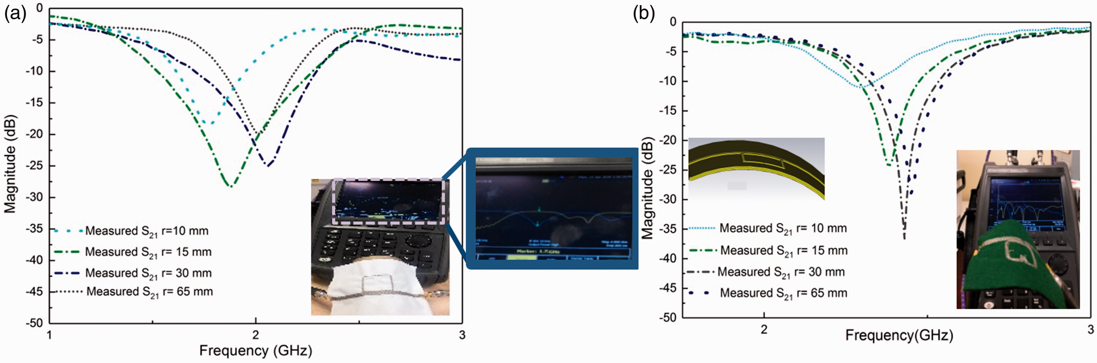
Conclusion
In this work, the utilization of different fabric materials for the implementation of e-textile MTM transmission lines is investigated with the aim of controlling the signal propagation in smart textile applications. The proposed design is a fully embroidered conductive thread transmission line loaded with conductive yarn SRRs on felt and cotton substrates. A significant agreement is achieved for the EM layout simulations and the experimental results. The measurement results exhibit a well-defined stop-band of 1.3 GHz on the felt substrate and 1 GHz on the cotton substrate with a high level of signal rejection. Also the effects of bending of the manufactured e-textiles have been tested and quantified, obtaining a relatively low impact on the resonance frequency of the proposed designs in terms of typical bending parameters due to conformal values of the human body shape.
Footnotes
Declaration of conflicting interests
The authors declared no potential conflicts of interest with respect to the research, authorship and/or publication of this article.
Funding
The authors disclosed receipt of the following financial support for the research, authorship, and/or publication of this article: This work was supported by the Spanish Government MINECO (project TEC2016-79465-R).