
Abstract
Novel SrAl2O4:Eu2+, Dy3+/SiO2-coated red-emitting coumarin color converter (SiO2@RECC)/polyamide 6 (PA6) luminous fibers with warm-toned luminescence color were prepared on the basis of the energy transfer and color conversion from SrAl2O4:Eu2+, Dy3+ to RECC. The mass concentrations of RECC used in the fibers were adjusted to obtain different luminescence colors. Scanning electron microscopy images, photoluminescence (PL) emission spectra, RGB color coordinates, luminescence photos, and luminescence lifetimes were analyzed. Results demonstrated that the PL emission spectra of luminous fibers contain two emission peaks in the range of 475–700 nm. The increase in RECC concentration contributed to the gradual redshift of the second emission peak, and the ratio of the second emission maximum to the first emission maximum also increased gradually. The luminescence color of the fibers shifted gradually toward red in the dark. Moreover, the fibers showed light yellow, yellow, orange, and orange-reddish luminescence in the dark when the mass concentrations of RECC were fixed at 0.1%, 0.6%, 1.0%, and 1.4%, correspondingly. The luminescence lifetimes of the fibers can be sustained for at least 13,288 s. The prepared warm-toned SrAl2O4:Eu2+, Dy3+/SiO2@RECC/PA6 luminous fibers have considerable application prospects, given their excellent luminescence properties.
Warm-toned luminous fibers show numerous potential applications in household textiles, clothing, embroidery textiles, and shoe and toy fabrics due to their multicolored luminescence emission in dark environments.1,2 The luminescence of luminous fibers originates from long-lasting phosphors inside the fibers, and the yellowish-green-emitting SrAl2O4:Eu2+, Dy3+ (SAOED) is the most commonly used long-lasting phosphor because of its high luminescence intensity and long luminescence lifetime.3,4 However, the SAOED luminous fiber is difficult to use in various luminous-related products given its monotonous and cool-toned yellowish-green luminescence. Although warm-toned and color-tunable luminous fibers are urgently required, an appropriate long-lasting phosphor that can satisfy luminescence intensity and durability requirements is difficult to find.
Energy transfer is a good approach to obtaining specific luminescence emission and color change. 5 For example, Pan et al. 6 reported a core shell-shaped ATTO-Rho101 dye embedded in a Y3Al5O12:Ce3+:Ce3+@SiO2 composite, which can enhance the red emission of Y3Al5O12:Ce3+ based on the energy transfer from ATTO-Rho101 dye to Y3Al5O12:Ce3+:Ce3+ phosphor. Li et al. 7 synthesized color-tunable Y3Al2Ga3O12:Tb3+, Eu3+ phosphors with efficient energy transfer; the emission color of this phosphor can be tuned from green, yellow, and red by controlling the energy transfer between Tb3+ and Eu3+ ions. Color conversion enables the emission of warm-toned luminescence by combining two or more kinds of luminescence colors. 8 Xia et al. 9 combined CaAl2O4:Eu, Nd as a persistent blue donor phosphor with Lu3Al5O12:Ce and four other conversion phosphors to obtain colorful persistent luminescence spectra. Yang et al. 10 obtained a blue organic light-emitting diode (LED) with white luminescence using an inorganic red aluminate phosphor as the color converter.
Warm-toned luminous fibers can be prepared by utilizing the appropriate luminescence light source based on energy transfer and color conversion. Here, the long-lasting SAOED phosphor and a SiO2-coated red-emitting coumarin color converter (SiO2@RECC) were used to provide persistent yellowish-green luminescence and red fluorescence, respectively. Polyamide 6 (PA6) was used as the fiber substrate given its overwhelming advantages in intensity, abrasive resistance, and weight over other synthetic fibers to broaden the application of warm-toned luminous fibers in sportswear, luminous shoes, and embroidery fabrics.11–13 Then, multicolored SAOED/SiO2@RECC/PA6 luminous fibers with warm-toned luminescence were prepared by adjusting the mass concentrations of SiO2@RECC in melt spinning. The morphology and luminescence properties of the fibers, including photoluminescence (PL) emission spectra, CIE-1931 chromaticity coordinates, luminescence images, lifetimes, and luminescence emission models, were systematically discussed. The results of the present study are crucial for the production of multicolor luminous fibrous products with warm-toned emission color based on luminescence energy transfer and color conversion without requiring the use of a long-lasting multicolor warm-toned phosphor.
Experimental details
Preparation of SrAl2O4:Eu2+, Dy3+/SiO2@RECC/PA6 luminous fibers
We have previously described the method used to prepare raw SAOED and RECC materials.14,15 To enhance the thermal stability of RECC and reduce the damage of high temperature to RECC in the subsequent melt-spinning process, the RECC was coated with a SiO2 layer in accordance with the following method prior to melt spinning.
Firstly, 3.47 g of tetraethoxysilane (TEOS, analytic grade purity) was added to a mixture of absolute alcohol (C2H5OH) and deionized water (H2O). The molar ratio of TEOS to C2H5OH and H2O was controlled at 1:30:20. Secondly, the mixture was transferred to a three-necked flask and stirred for 30 min in a water bath at 60℃. Meanwhile, diluted sulfuric acid (H2SO4) solution was used to adjust the pH value to 3. Thirdly, 1 g of the as-prepared RECC particles was added to the abovementioned three-necked flask. Stirring was maintained for 1.5 h. Finally, after finishing the reaction, the mixture was washed thrice using a vacuum filtration device and deionized water and dried in an oven at 70℃ for 12 h to get the SiO2@RECC composite.
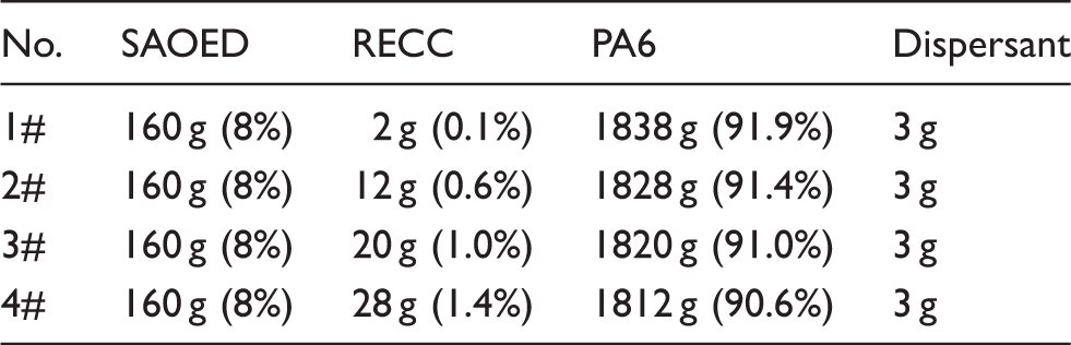
The prepared SAOED and SiO2@RECC were mixed with fibroid PA6 particles to prepare the SAOED/SiO2@RECC/PA6 luminous fibers through the melt-spinning technique. The melt-spinning device is depicted in Figure 1. Before melt spinning, the mixture of SAOED, SiO2@RECC, and PA6 particles was placed in a drying oven at 110℃ for 6 h. To investigate the effect of SiO2@RECC concentrations on the luminescence colors of the final luminous fibers, the mass ratios of the SAOED, RECC, and PA6 were varied in accordance with the values listed in Table 1. In addition, minimal dispersant was required to ensure that the SAOED and SiO2@RECC were dispersed well in the fiber substrate. Four sets of luminous fibers (1#–4#) were obtained. The SiO2@RECC concentrations of the four fibers were set to 0.1%, 0.6%, 1.0%, and 1.4%, respectively.
Melt-spinning procedure for preparing SrAl2O4:Eu2+, Dy3+/SiO2-coated red-emitting coumarin color converter/polyamide 6 luminous fibers. Mass proportions of SrAl2O4:Eu2+, Dy3+ (SAOED), red-emitting coumarin color converter (RECC), polyamide 6 (PA6) particles, and dispersant for preparing SAOED/RECC/PA6 luminous fibers
Characterization
The sample morphology images were captured using field emission scanning electron microscopy (SEM) (FEI, Nicole Apreo), and the particle sizes of SAOED and SiO2@RECC were statistically analyzed using a laser particle sizer (OMEC LS-POP, China). The PL excitation and emission spectra of the samples were acquired using a spectrofluorometer (Edinburgh FS-5), and an MCS-1000 long-lasting luminescence spectral measuring system was used to determine the RGB chromaticity coordinates of the luminous fibers. In addition, the luminescence images of the luminous fibers were inspected in the dark using a Nikon D5600 camera through a light box equipped with a D65 light. Luminescence decay curves were recorded using a PR-305 afterglow luminescence meter, where the fibers were excited by an ultraviolet (UV) light at 365 nm and luminance of 1000 lx for 15 min. The MCS-1000 long-lasting luminescence spectra measuring system and PR-305 afterglow luminescence meter were provided by SENSING Instruments Co., Ltd, China. The photos and data were recorded 5 s after removing the excitation light to acquire luminescence photos, CIE-1931 chromaticity coordinates, and luminescence decay curves. All measurements were obtained at room temperature.
Results and discussion
SEM morphology
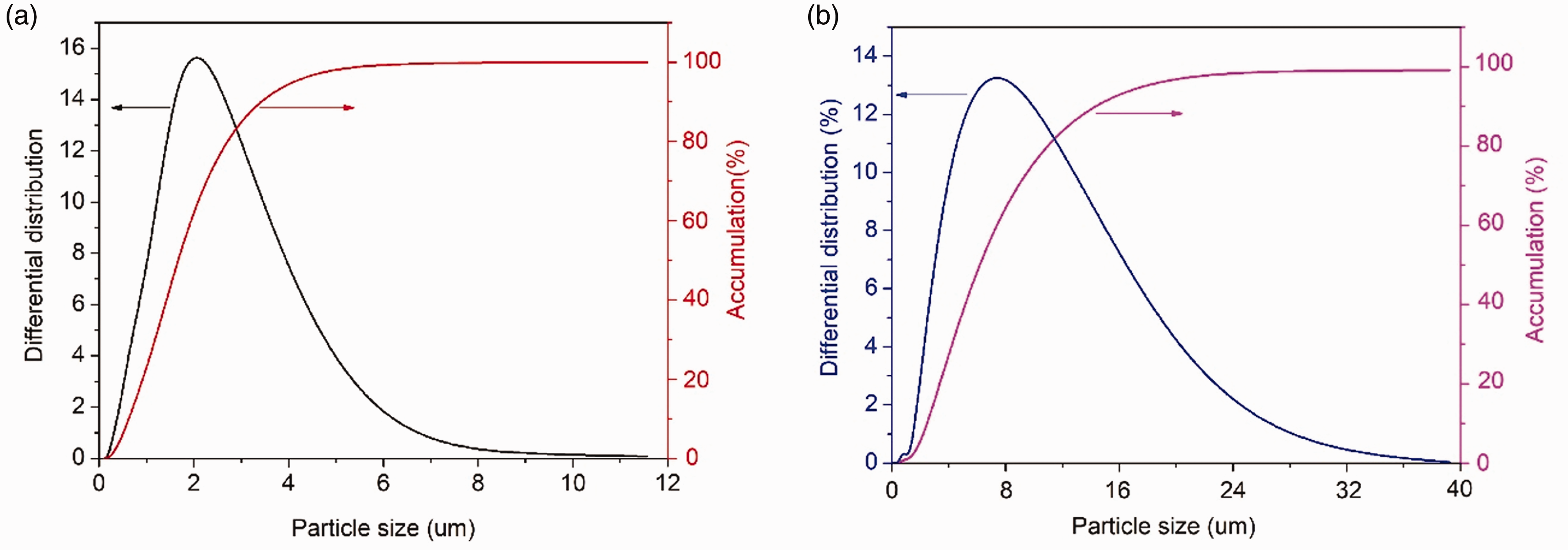
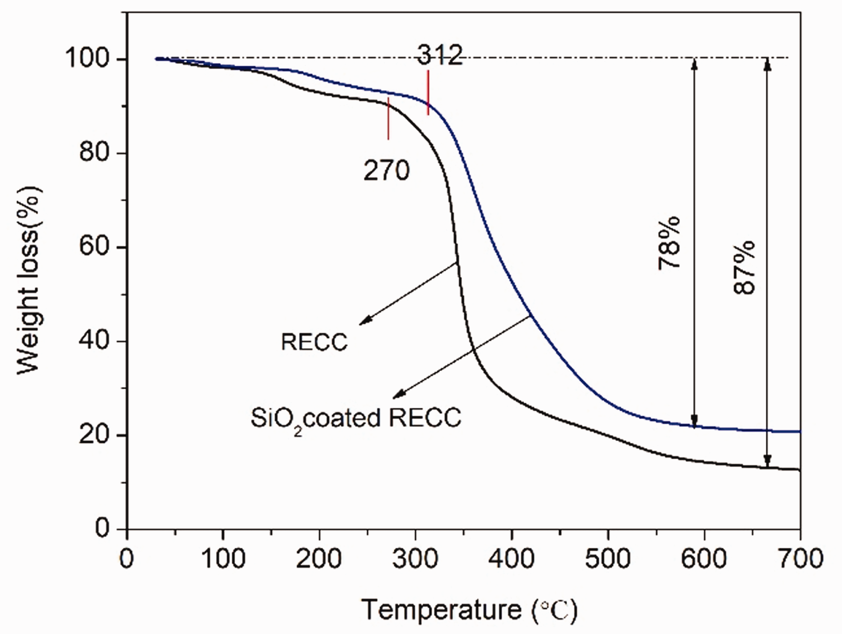
The images of the SiO2@RECC and SAOED used to provide red fluorescence and yellowish-green long-lasting luminescence are presented in Figure 2. The particle size distributions of SiO2@RECC and SAOED are displayed in Figure 3. SiO2@RECC had a globular shape and good dispersion without aggregation. Most particle size distributions were less than 2 µm, which is appropriate for melt spinning. The SAOED particles showed similar characteristics to those of the SiO2@RECC particles. Although the SAOED particles had an irregular shape, their size distribution concentrated at 7 µm, which is also suitable for melt spinning. The thermogravimetric (TG) curves of the uncoated RECC and SiO2@RECC composites are illustrated in Figure 4. When the temperature was increased to 270℃, the molecular chain of the uncoated RECC underwent TG decomposition with dramatic weight loss. The total weight loss of SiO2@RECC reached 87% when the temperature was increased to 700℃. The molecular chain of the SiO2@RECC composite underwent decomposition at 312℃, and the thermal tolerance of this composite improved by 32℃ relative to that of uncoated RECC. This result demonstrated that the thermal endurance of RECC was enhanced to 317℃ from 270℃, and the melting temperature of PA6 (275℃) would not cause any damage to RECC after coating with the SiO2 layer. With the continuous increase in the temperature to 700℃, the total weight loss of SiO2@RECC reached 78% and decreased by 9% in comparison with that of uncoated RECC. This result was ascribed to the residual undecomposed SiO2. Therefore, given the abovementioned analysis, SiO2@RECC and SAOED can be used to produce SAOED/SiO2@RECC/PA6 luminous fibers.
Scanning electron microscopy images of SiO2-coated red-emitting coumarin color converter (a) and SrAl2O4:Eu2+, Dy3+ lasting phosphor phosphors (b). Particle size distribution of SiO2-coated red-emitting coumarin color converter (a) and SrAl2O4:Eu2+, Dy3+ lasting phosphor phosphors (b). Thermogravimetric curves of uncoated red-emitting coumarin color converter (RECC) and SiO2-coated RECC (SiO2@RECC composite).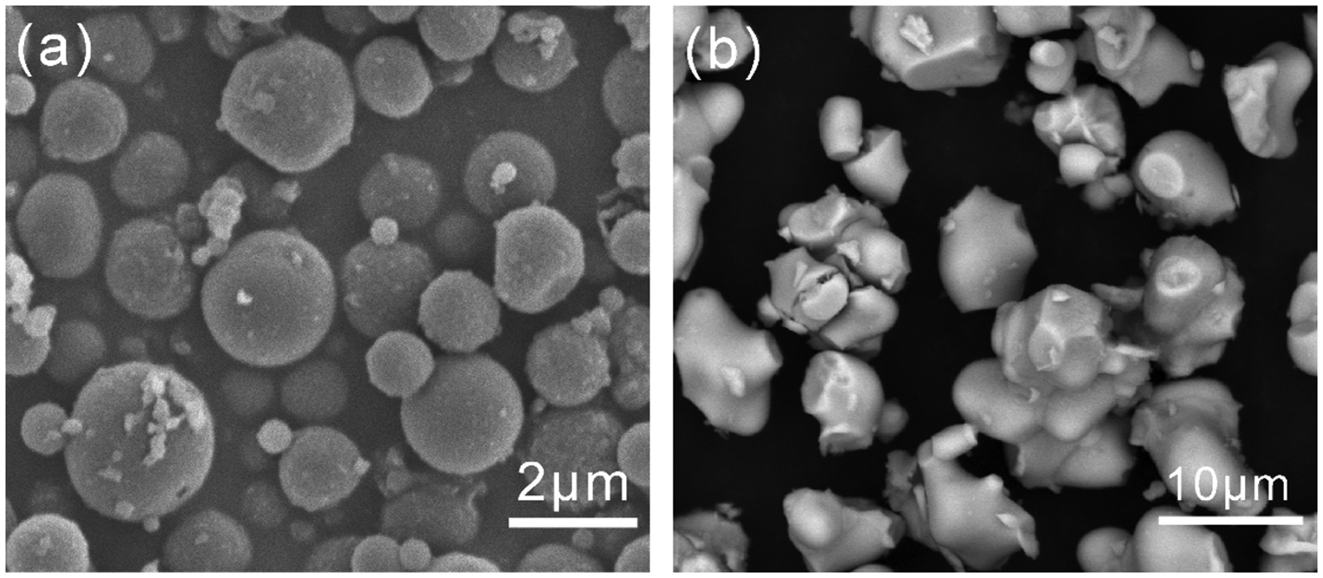
The SEM images of the four sets of luminous fibers prepared with different concentrations of SiO2@RECC are shown in Figure 5. Most SAOED and SiO2@RECC particles dispersed well in the fiber. Nevertheless, small quantities of SAOED and SiO2@RECC particles remained exposed or embedded on the surfaces of the fibers, considering the extruding effect of the liquated PA6 and accounted for the coarse surfaces of the fibers. In Figure 5, even if the fiber was thicker than some fibers because of the absence of drafting in melt spinning, the surface morphology of the four sets of SAOED/SiO2@RECC/PA6 luminous fibers showed a negligible difference, thereby implying that SiO2@RECC concentrations slightly influence fiber morphology.
Scanning electron microscopy images of the four sets of SrAl2O4:Eu2+, Dy3+/SiO2-coated red-emitting coumarin color converter (SiO2@RECC)/polyamide 6 luminous fibers (1#–4#) prepared with different SiO2@RECC concentrations (wt% = 0.1, 0.6, 1.0, 1.4).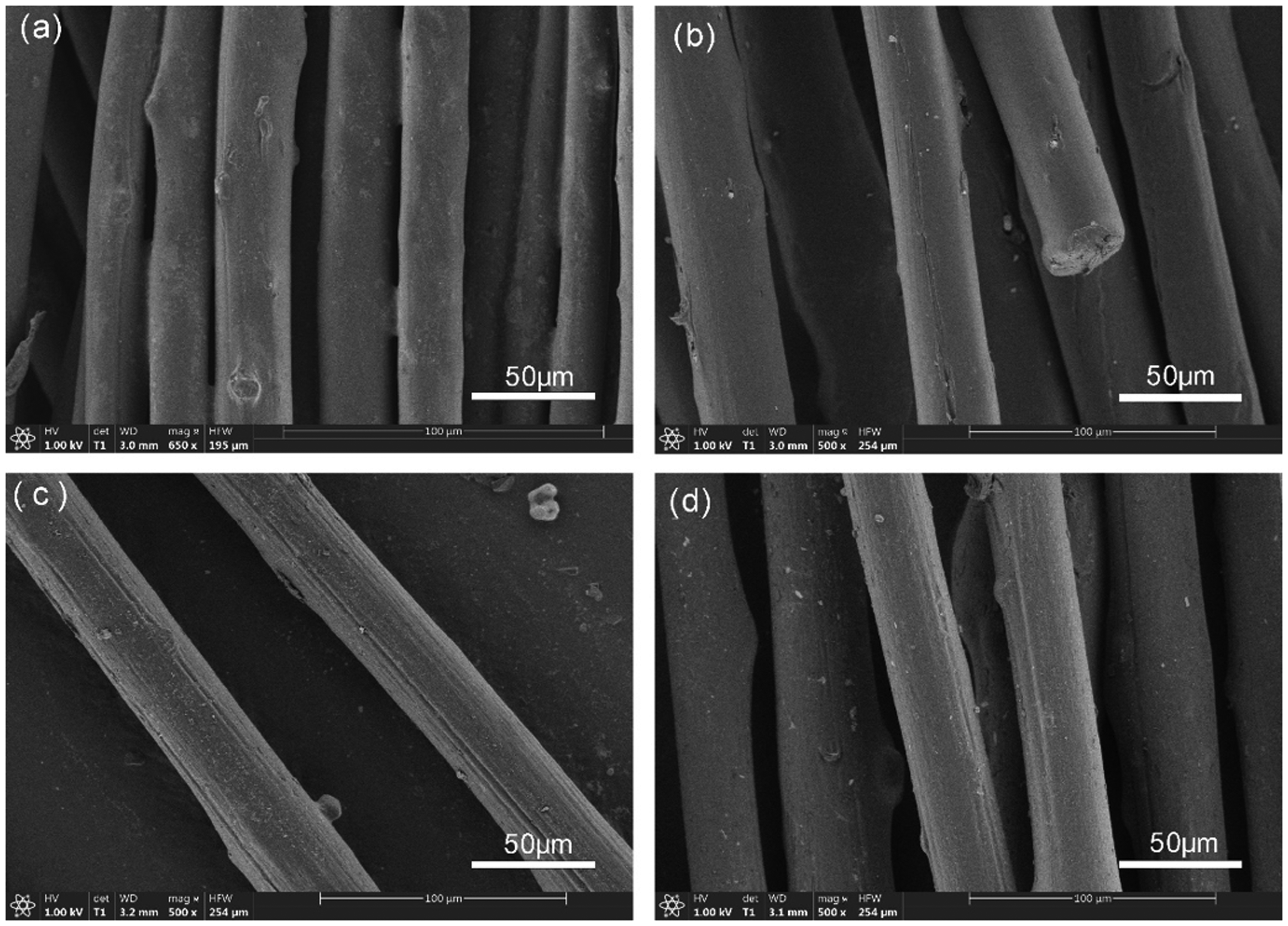
PL emission
The PL emission spectra of the four sets of luminous fibers were recorded and are illustrated in Figure 6(a). In contrast to the emission spectra of SAOED and SiO2@RECC, each containing a single emission peak,
14
the emission spectra of the four sets of luminous fibers consisted of two emission boards in the range of 475–700 nm with two emission peaks. In contrast to the first peak at 510 nm, which corresponded to the emission peak of SAOED, the second emission peak underwent a gradual redshift with the increase in the mass concentration of SiO2@RECC, thus implying that the mass concentration of SiO2@RECC contributes to the gradual movement of the luminescence color toward red.16,17 In comparison with the emission peak wavelength of SiO2@RECC at 608 nm, the second peak wavelength of the four sets of luminous fibers had blue-shifted to 578, 591, 596, and 600 nm when the mass concentrations of SiO2@RECC were fixed at 0.1%, 0.6%, 1.0%, and 1.4%, correspondingly; these results indicated that the luminescence colors of the four sets of luminous fibers are located between yellowish-green and red and are considered warm-toned colors.
18
(a) Photoluminescence emission spectra of the four sets of SrAl2O4:Eu2+, Dy3+/SiO2-coated red-emitting coumarin color converter (SiO2@RECC)/polyamide 6 luminous fibers (1#–4#) prepared with different SiO2@RECC concentrations (wt% = 0.1, 0.6, 1.0, 1.4). (b) Ratio of the second emission maximum to the first emission maximum (Ib/Ia).
The luminescence color would also be affected by the ratio of the second emission maximum to the first emission maximum. The ratios of the second emission maximum to the first emission maximum (Ib/Ia) with different mass concentrations of SiO2@RECC are demonstrated in Figure 6(b). The linear increment in Ib/Ia ratio with the increase in SiO2@RECC concentration indicated that the proportion of warm-toned colors increases relative to that of the cool-toned yellowish-green at 510 nm. The increase in the Ib/Ia value caused by the increase in the SiO2@RECC concentration also contributed to the shift of luminous fiber emission color toward red.
CIE-1931 chromaticity coordinates
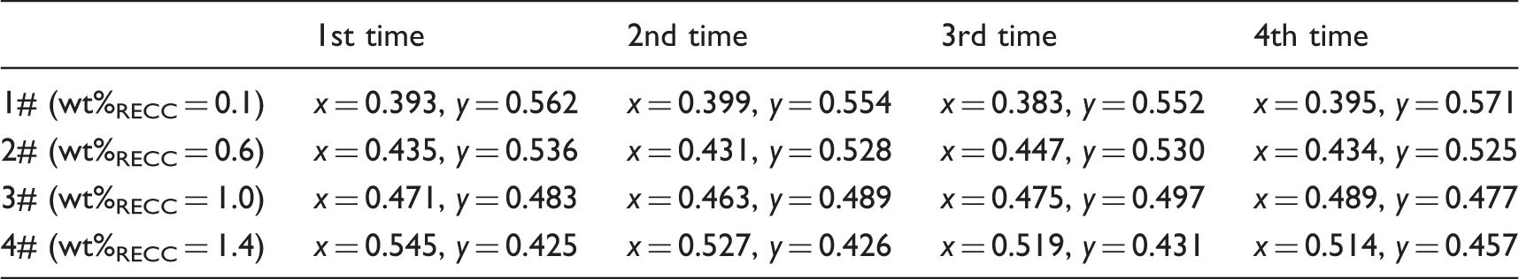
To determine the specific emission color of the four sets of luminous fibers, their RGB color coordinates were measured, and each set of fiber were measured four times with 30 s time intervals for accuracy. The results were represented by a CIE-1931 chromaticity diagram. In Figure 7, the luminescence color positions of the four sets of prepared luminous fibers were all located in the warm-toned area and moved to red gradually with the increase in SiO2@RECC in accordance with the PL emission spectra. Specifically, when the mass concentrations of SiO2@RECC used in the luminous fiber were 0.1%, 0.6%, 1.0%, and 1.4%, the corresponding emission colors were light yellow and then moved to yellow, orange, and orange-reddish, respectively. Table 2 provides the specific RGB coordinate values of the fibers with four measurements.
CIE-1931 chromaticity coordinate diagram of the four SrAl2O4:Eu2+, Dy3+/SiO2-coated red-emitting coumarin color converter (SiO2@RECC)/polyamide 6 luminous fiber sets (1#–4#) prepared with different SiO2@RECC concentrations (wt% = 0.1, 0.6, 1.0, 1.4). RGB coordinate values of the four SrAl2O4:Eu2+, Dy3+/SiO2-coated red-emitting coumarin color converter/polyamide 6 luminous fiber sets (1#–4#) with four measurements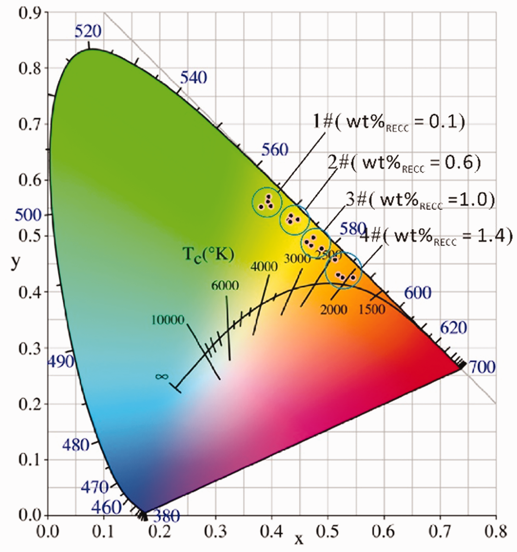
The color shift of the luminous fibers may be ascribed to the synergistic effect of the luminescence energy transfer and color conversion of SAOED and SiO2@RECC distributed in the fiber. In Figure 8, the SAOED and SiO2@RECC particles were dispersed well in the fiber. When the fiber was exposed to the excitation light, the SAOED and SiO2@RECC particles would be excited and then emit long-lasting yellowish-green luminescence and red fluorescence simultaneously. The excitation spectrum of RECC and the emission spectrum of SAOED overlapped in the wavelength range of 450–600 nm, thereby implying that SiO2@RECC can be excited by the yellowish-green luminescence of SAOED.
14
Therefore, when the external excitation light is removed, the long-lasting luminescence of SAOED would transfer to SiO2@RECC (energy transfer) to stimulate RECC continually to release red fluorescence and enable warm-toned color conversion based on the color combination. The increase in the amount of SiO2@RECC used indicated that the amount of yellowish-green luminescence can be transferred to RECC and then the amount of red fluorescence can be released. These effects resulted in the gradual shift of the fiber emission color to red.
Luminescence emission model for SrAl2O4:Eu2+, Dy3+ (SAOED)/SiO2-coated red-emitting coumarin color converter (SiO2@RECC)/polyamide 6 luminous fibers.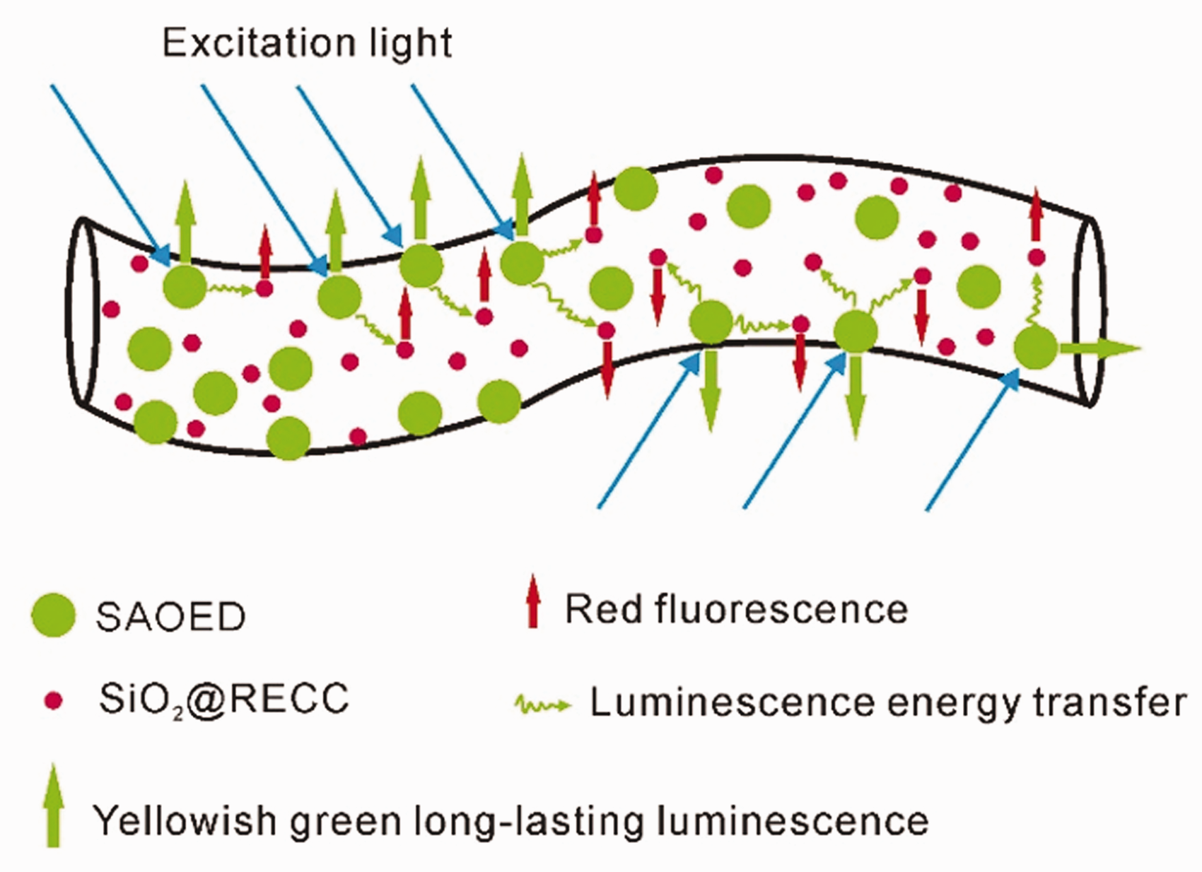
The luminescence photos of the four sets of luminous fibers in the dark after removing the excitation light and their daylight photos are displayed in Figure 9. The physical color of the luminous fibers shown in the daylight photos had reddened because of the increase in SiO2@RECC concentration. In a dark environment without the excitation light, all four sets of fibers presented a warm-toned luminescence color. This result was consistent with the RGB color coordinates demonstrated in Figure 7. A small color difference was observed between the RGB color coordinates of the fiber and real luminescence photos in the dark. The color mismatch between the RGB color coordinates of the fiber and real luminescence images was attributed to the difference between the photopic sensitivities of the two measurement devices.
Comparison of the color images of four SrAl2O4:Eu2+, Dy3+/SiO2-coated red-emitting coumarin color converter/polyamide 6 luminous fiber sets (1#–4#) in the daytime (a) with luminescence images acquired in the dark after removing the excitation light (b).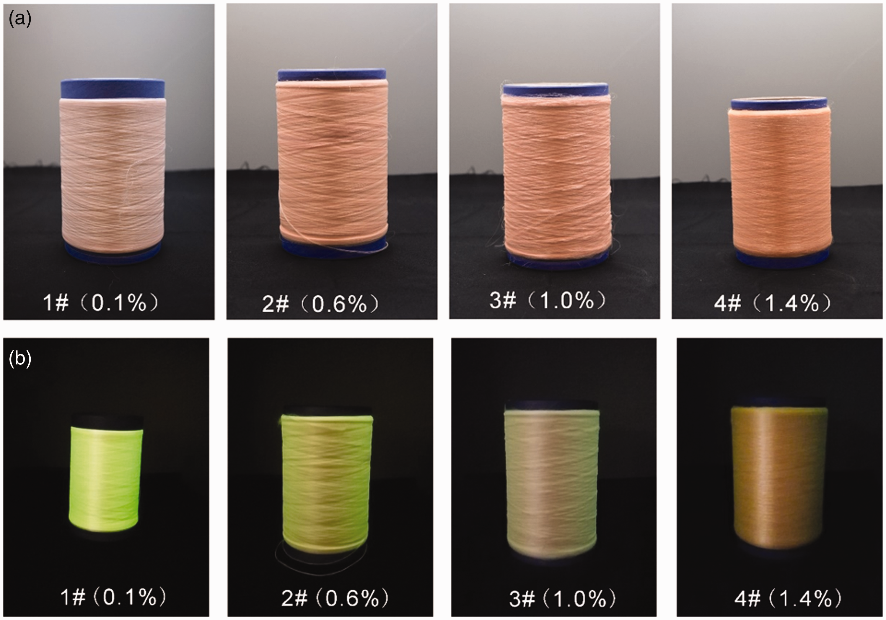
Luminescence lifetime
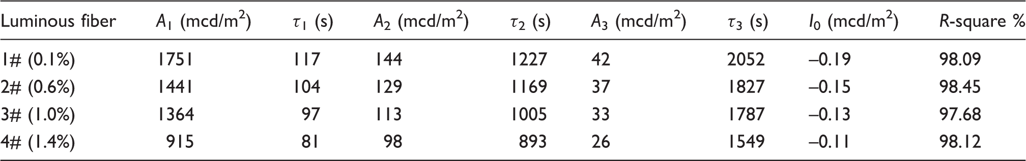
In addition to the emission color, the luminescence lifetimes of the SAOED/SiO2@RECC/PA6 luminous fibers were analyzed in accordance with the luminescence decay curves exhibited in Figure 10. Similar to the decay curve of SAOED, the luminescence decay curves of the prepared four sets of warm-toned luminous fibers followed an exponential decay trend, thus indicating that the long-lasting luminescence of the SAOED/SiO2@RECC/PA6 luminous fibers mainly originated from SAOED. In addition, increasing the mass concentration of SiO2@RECC in the fiber adversely affected luminescence brightness, as reflected by the decline in the initial luminescence from 1.751 cd/m2 to 1.441, 1.364, and 0.915 cd/m2 when SiO2@RECC concentrations were increased from 0.1% to 0.6%, 1.0%, and 1.4%. The decrement in the initial luminescence brightness can also reduce luminescence lifetime.19,20 The counteractive effect of SiO2@RECC on energy transfer efficiency was likely responsible for the decline in the fiber brightness.
21
In Figure 8, the luminescence energy transfer from SAOED to SiO2@RECC was affected by the SiO2@RECC concentration. The presence of SiO2@RECC around SAOED in the fiber would hinder the absorbance of the external excitation light by SAOED and result in the decline in the SAOED luminescence brightness and reduce energy transfer from SAOED to SiO2@RECC. During the transmission of the yellowish-green luminescence emitted by SAOED to the outside of the PA6 fiber substrate after removing the excitation light, the surrounding SiO2@RECC would inevitably act as a barrier for this luminescence, thus reducing the luminescence brightness of the fiber. The reduction in luminescence brightness intensified with the increase in the amount of SiO2@RECC surrounding SAOED. An increase in the SiO2@RECC concentration may result in the squeezing and aggregation of SAOED and SiO2@RECC in the fibers, thus limiting energy transfer efficiency from SAOED to SiO2@RECC and reducing the luminescence brightness and lifetime of the luminous fibers.
Luminescence decay curves of the four SrAl2O4:Eu2+, Dy3+/SiO2-coated red-emitting coumarin color converter (SiO2@RECC)/polyamide 6 luminous fiber sets (1#–4#) prepared with different SiO2@RECC concentrations (wt% = 0.1, 0.6, 1.0, 1.4).

Decay times and brightness of the third-order exponential components of four SrAl2O4:Eu2+, Dy3+/SiO2-coated red-emitting coumarin color converter (SiO2@RECC)/polyamide 6 luminous fiber sets (1#–4#) prepared with different SiO2@RECC concentrations (wt% = 0.1, 0.6, 1.0, 1.4)
Conclusions
We successfully prepared multicolored SAOED/SiO2@RECC/PA6 luminous fibers with warm-toned luminescence. SAOED and SiO2@RECC particles dispersed well in the PA6 fiber substrate when the mass concentration of RECC ranged from 0.1% to 1.4%. The PL emission spectra of the luminous fibers consisted of two emission boards in the range of 475–700 nm with two emission peaks. The increase in the SiO2@RECC concentration contributed to the redshift of the second emission peak, and the increment in the ratio of the first emission maximum to the second emission maximum accounted for the shift of the luminescence color toward red. The luminescence color of the fiber in the CIE-1931 chromaticity coordinate diagram was located in the light yellow, yellow, orange, and orange-reddish regions when the mass concentrations of SiO2@RECC in the fiber were fixed at 0.1%, 0.6%, 1.0%, and 1.4%, respectively. The slight color difference between the RGB color coordinates of the fibers and the real luminescence photos in the dark was ascribed to the difference between the photopic sensitivities of the two measurement devices. Nevertheless, increasing SiO2@RECC negatively affected the luminescence lifetime of the fiber, and the lowest lifetime exceeded 3.6 h when the mass concentration of SiO2@RECC was 1.4%.
Footnotes
Declaration of conflicting interests
The authors declared no potential conflicts of interest with respect to the research, authorship, and/or publication of this article.
Funding
The authors disclosed receipt of the following financial support for the research, authorship, and/or publication of this article: This work was supported by the projects the Talents project of Minjiang University in 2018 (No. MJY18007), The Open Project Program of Fujian Key Laboratory of Novel Functional Textile Fibers and Materials (Minjiang University), China (No. FKLTFM2004), The Open Project Program of Key Laboratory of Eco-textiles, Ministry of Education, Jiangnan University (No. KLET1801), and the Science and Technology Projects of Fujian Province (No. 2019H6019).