



Abstract
Yarn tension during ring spinning is influenced by the shape of the balloon. With the high speed of ring spinning, the existing balloon control technology will have problems with yarn breakage caused by increased tension and yarn wear during the spinning process. Therefore, this article takes the naturally formed multi-balloon as the research object and analyzes the force of the yarn in the balloon section to establish the mathematical model of the steady-state balloon section. Then we selected the appropriate parameters to compare the balloon trajectory graph obtained by simulation and experiment, to verify the validity of the mathematical model. Finally, the relationship between the yarn tension and the number of balloon segments under different balloon heights and spindle speeds, and the conditions for the stable shape of multi-balloon are discussed. It was found that under different balloon shapes, increasing the number of balloon segments can effectively reduce the yarn tension at the yarn guide, and the stable conditions of balloons with different numbers of segments under certain process conditions. The findings are of great significance to the subsequent research on the technological parameters of low-tension spinning and the structural design of ring-spinning machines.
In the textile industry, ring spinning is an essential process for producing high-quality yarn, and its process structure diagram is shown in Figure 1-1. However, the traditional single-balloon ring spinning speed is low, so the output of a single-ring spinning spindle is not high. Although the speed of the double-balloon ring spinning with the balloon-control ring has increased with the continuous improvement of spinning efficiency, the increase of the spindle speed increases the friction between the yarn and the balloon-control ring. This increases the tension of the yarn, which leads to aggravated yarn wear, affects the quality of spinning, and reduces spinning efficiency. The naturally formed multi-balloon can reduce the tension of the yarn while avoiding the friction between the yarn and the balloon-control ring, which can effectively alleviate the above problems. At the ITMA exhibition in 2019, a Spanish company successfully applied multi-balloon ring spinning technology to ring spinning. However, this technology is unclear regarding the relationship between balloon shape and yarn tension under different sections. 1 Therefore, the relationship between the multi-balloon shape and the spun yarn requires study through experiment and simulation to find out the range of spindle speed corresponding to different numbers of balloon segments suitable for low-tension spinning, and to provide a basis for determining the spinning process parameters.
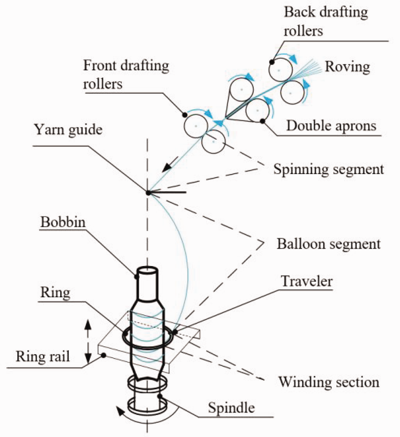
Schematic of traditional ring spinning.
Since the 1950s and 1960s, scholars worldwide have been researching the yarn balloon. Mack. 2 established a second-order nonlinear differential equation for the balloon and simplified the balloon into a sinusoidal curve to describe the shape of the balloon and the tension it receives. Batra et al.3,4 gave the numerical solution of the quasi-steady-state balloon equation. However, this method is not conducive to the analysis of actual spinning parameters. Fraser 5 solved the balance equation of the yarn passing through the traveler region as a boundary condition of the free balloon and found that, under certain conditions, the relationship between the mass of the traveler and the yarn tension at the yarn guides multiple factors. In addition, Fraser et al. 6 also studied the yarn tension and balloon stability when the balloon is added to the balloon-control ring to form a double-balloon. It has been found that when the installation position of the balloon-control ring is half of the height of the entire balloon, the reduction of the yarn tension is most obvious.
In the actual ring-spinning process, the radius of gyration at each part of the balloon is different, resulting in inconsistent yarn tension at each part of the balloon, and so the yarn linear density at each part of the balloon is not uniform. Fraser et al.7,8 used the Gaussian distribution function to simulate the unevenness of yarn linear density and found that even if the difference in linear density uniformity of the balloon yarn is small, it will have a significant impact on the stability of the balloon. And Fraser 9 and Tang et al. 10 also studied the influence of the air drag coefficient on the yarn tension and found that the higher the yarn density, the greater the air drag coefficient, and the greater the air drag on the yarn. Tang et al.11,12 studied the effects of parameters such as yarn length, yarn linear density, and spindle speed on yarn tension in the balloon. The results showed that the longer the yarn length in the balloon, the lower the yarn tension, and increasing the yarn linear density or increasing the spindle speed will lead to the increase of yarn tension.
Due to the friction between the traveler and the ring, in traditional ring spinning we cannot further improve the spinning quality and spinning efficiency. Hossain et al. 13 replaced the traveler with a superconducting magnetic levitation device, established a mathematical model of the balloon considering the elasticity of the yarn, and studied the balloon shape and yarn tension of the yarn under high-speed rotation. Not only that, but Hossain et al. 13 also used industrial cameras to record the shape of the balloon and calculated the yarn tension by measuring the strain of the yarn.
Kuihua 14 used the method of the cylindrical coordinate system, taking the micro-element of yarn as the research object, established its mechanical balance equation, and gave the dimensionless differential equation for solving the balloon and tension. Yuan and Jin 15 analyzed the mechanism of various balloon control technologies, and combined the early conception of the small-diameter balloon-control ring and the latest multi-balloon-control ring high-speed rotation model. The practical application of the control scheme for opening and closing the small-diameter balloon was proposed. Hongbo and Renzhe 16 used the analytical method to give the approximate solution of the space curve of the ring-spinning balloon formed by the air drag. Renzhe and others17,18 focused on the plane balloon, and systematically studied and discussed the dynamics of the yarn, proposing to regard the balloon as a plane-polarized wave with the same frequency in two directions. In this way, the balloon equation can be expressed with an extremely simple mathematical formula, and the problem of the balloon resonance frequency and the limit balloon can be easily solved. Yu et al. 19 analyzed the relationship between the shape of the balloon and the internal tension of the yarn by establishing a mathematical model of multiple balloons, providing a certain reference for the high-speed ring spinning. Yin 20 analyzed the dynamic behavior of the yarn in the ring-spinning system deriving from Newton's second law and solved it with the finite difference method considering the nonlinear elastic yarn model.
In this article, the change law of balloon shape and yarn tension under a multi-balloon state is considered. Through experimental research and simulation, the influence of key spinning factors on spinning tension is discussed. And we aimed to find out the stable condition of different sections of yarn balloons under certain process conditions. This is of great significance for subsequent research on the technological parameters of low-tension spinning and the structural design of ring-spinning machines.
Mathematical model of the steady balloon
Since balloons are common in the field of spinning, the corresponding descriptions of balloons formed by different processes or equipment are different, and the balloon model established in this article can be used for the analysis of balloon shape and yarn tension in other processes. Therefore, the relevant names are unified, as shown in Figure 2-1.
The parameter
In the actual production process, the balloon is required to be in a steady state when the ring-spinning machine is spinning. At this time, the shape of the balloon and the yarn tension of the balloon remain stable, so the model established in this article is a mathematical model under the steady state condition of the balloon.
Due to the complex structure of the yarn, certain assumptions are made for the convenience of modeling:
The yarn is a slender and soft flexible body, and does not stretch or deform; The angular velocity of the spindle speed is constant; The yarn consists of a homogeneous material; The yarn balloon formed by the yarn rotation is in a steady state, ignoring the time-related items; In the actual process, when the yarn rotates to form a balloon, the yarn rotates at a high speed on the inner wall of the yarn guide. In this article, it is assumed that the position of the yarn at the top of the balloon (yarn guide) is constrained.
In this article, the shape of the balloon can be regarded as a space curve passing through the origin
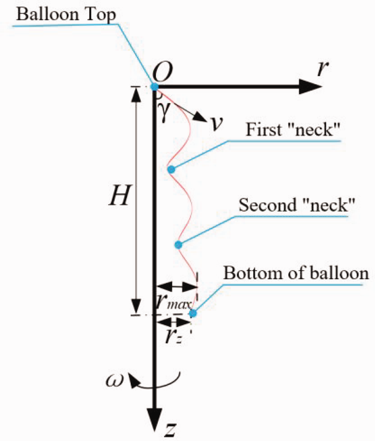
Steady-state balloon envelope profile.
The dynamic and static equilibrium equations of the three forces are:

Divide both sides by

When

Let the coordinates of any point

Let the tangent vector of any point

In the formula:

Derivation on both sides of formula (6) can obtain:

Decomposing the yarn tension into the spatial rectangular coordinate axis, we can get:
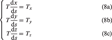
Therefore, from formula (8), the three components of formula (3) on the
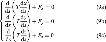
The radius of gyration at point

The yarn is continuously output at a line speed
The “centrifugal force”




Where

Substitute formulas (11) ∼ (14) into formula (9):
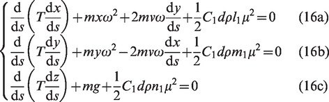
Due to the small influence of gravity, this article ignores the gravity effect of the yarn itself, and then multiplies the formula (16a) by


In the formula above
Simultaneous formulas (11) ∼ (15), further, formula (16) can be changed into:
The initial value of the mathematical model of the balloon segment:
The boundary value of the mathematical model of the balloon segment:


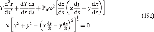



where
The height from the top of the balloon to the bottom of the balloon is
Simulation calculation and experimental verification of the multi-balloon
Simulation calculation of the multi-balloon
In this section, the simulation calculation of the mathematical model is carried out within the safe speed range that the experimental platform can achieve. After determining the initial conditions and the experimental parameters in the table below, the fourth-order Runge-Kutta methods are used for the numerical solution in MATLAB, and the effectiveness of the balloon segment mathematical model is verified under different spindle speed conditions. Select from 7000 r/min, 8000 r/min, 9000 r/min, 10,000 r/min, 11,000 r/min, and 12,000 r/min for simulation experiments, and we can obtain the three-dimensional space spiral curve, which is convenient for subsequent extraction of yarn contours, and then comparative analysis between experiments and guidelines.
Considering the length of the article, this article shows the highest speed, the lowest speed, and the middle two groups of data that can be achieved experimentally when the balloon height is 37 cm. The rest of the data are consistent with the conclusions verified in this article.
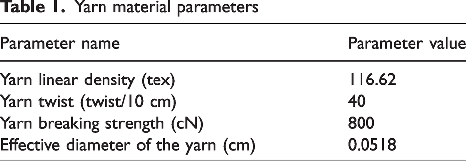
The material parameters involved in the experiment and simulation are shown in Table 1. Experimental and simulation parameters are shown in Table 2.
Yarn material parameters
Summary of experimental and simulation parameters

The three-dimensional spiral curve obtained when the balloon height is 37 cm and the speed is 7000 r/min is shown in Figure 3-1:
The three-dimensional spiral curve obtained when the balloon height is 37 cm and the speed is 9000 r/min is shown in Figure 3-2:
The three-dimensional spiral curve obtained when the balloon height is 37 cm and the speed is 11,000 r/min is shown in Figure 3-3:
Force analysis of arbitrary yarn micro-element 
The three-dimensional spiral curve obtained when the balloon height is 37 cm and the speed is 12,000 r/min is shown in Figure 3-4:
Schematic diagram of the "force" on the balloon yarn.
From the above simulation analysis, it can be seen that the curve obtained by the simulation conforms to the yarn balloon profile formed in the ring-spinning process. However, due to the setting of the above-mentioned boundary conditions and the above-mentioned assumptions for establishing the steady-state mathematical model, there are errors between the simulation and the actual situation. Therefore, it is necessary to further verify the validity of the mathematical model by comparing experiments with simulation.
Experimental verification of the multi-balloon
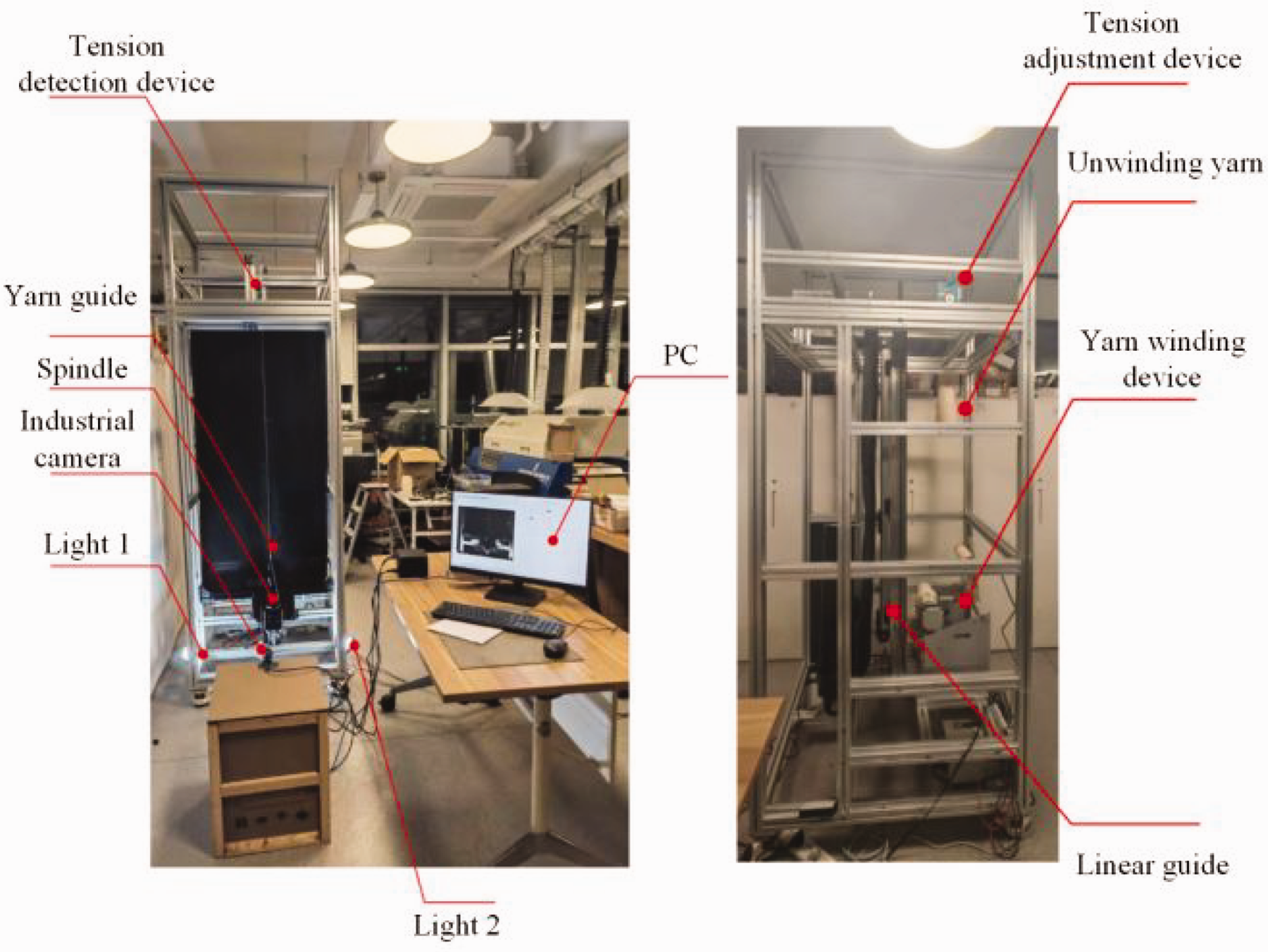
In order to verify the effectiveness of the mathematical model of the balloon, an experimental device was designed and built in this study, and the mathematical model of the balloon was verified. The experimental device includes a machine vision image acquisition module, a yarn winding module, a high-speed rotation module, and a tension adjustment module. The overall scheme is shown in Figure 3-5.
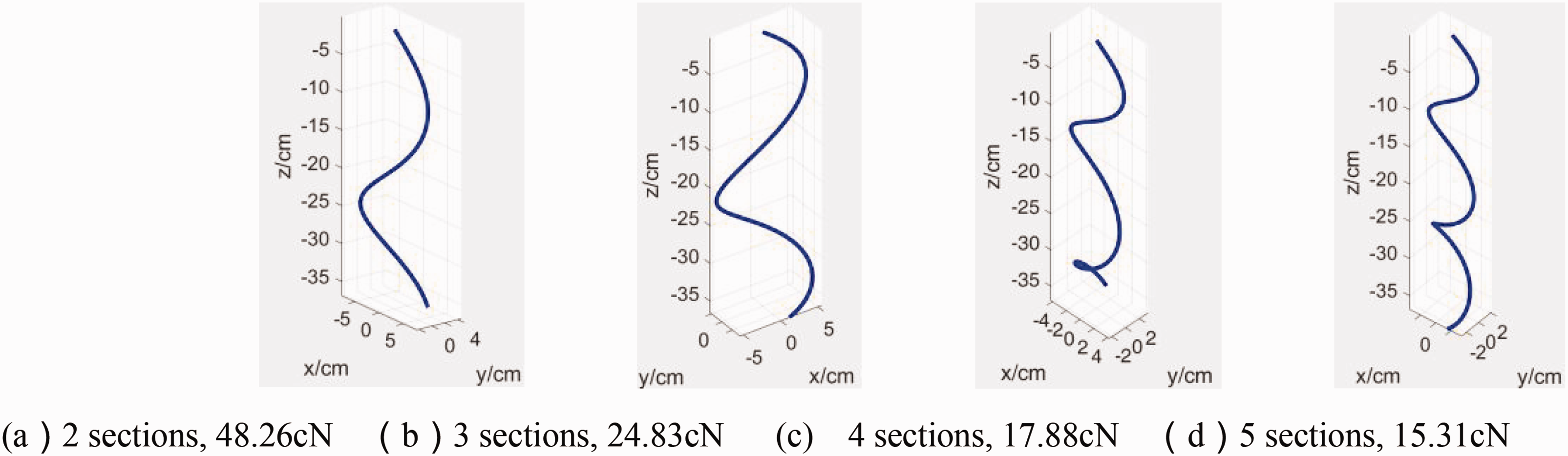
The number of balloon sections and yarn tension value when the balloon height is 37 cm and the speed is 7000 r/min.
The winding process starts with the unwinding yarn and first passes through the tension adjustment and detection device to control the yarn tension. Then through the yarn guide and the rotor, the process will form a balloon, and the industrial camera between the yarn guide and the rotor cup will capture the formed stable balloon, finally, the yarn will be wound up through the winding roller. Among them, the linear guide rail is mainly used to adjust the height of the yarn guide to change the size of the balloon during the experiment, and the PC and light source are used to assist in the shooting of the industrial camera.
The image acquisition module mainly includes industrial cameras, light sources, PC computers, etc. through the image acquisition module to obtain the balloon trajectory envelope profile under specific parameter conditions.
The main function of the tension adjustment module is to keep the yarn tension relatively constant, thereby forming a steady-state yarn balloon. This study used an oil pressure-damping tension adjustment device to stabilize the yarn tension.
The physical picture of the high-speed rotary module is shown in Figure 3-6, which mainly includes yarn guide, three-phase asynchronous motors, frequency converters, rotors, etc. The three-phase asynchronous motor is connected to the shaft where the rotor is located through a synchronous belt and then drives the rotor to rotate, and the frequency converter controls the speed and steering of the three-phase asynchronous motor. Then drive the rotor rotates, and the frequency converter controls the speed and steering of the three-phase asynchronous motor.

The number of balloon sections and yarn tension value when the balloon height is 37 cm and the speed is 9000 r/min.
The yarn winding module is shown in Figure 3-7. The yarn-winding module is mainly composed of a yarn-winding device. In this experiment, the groove drum is selected for winding.
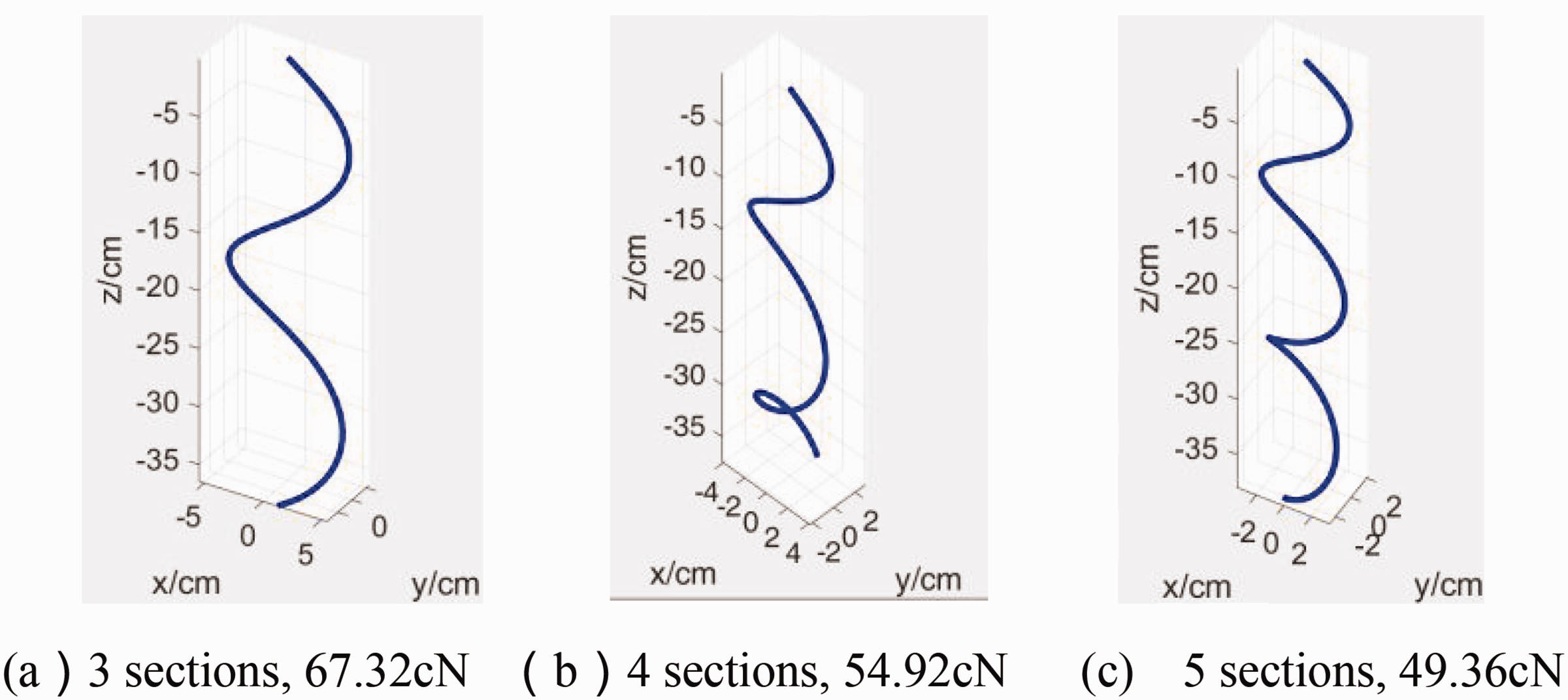
The number of balloon sections and yarn tension value when the balloon height is 37 cm and the speed is 11,000 r/min.
The unwound yarn goes through the modules described above respectively. A yarn balloon is formed between the rotor cup and the yarn guide, and the image acquisition module photographs the trajectory envelope profile of the yarn balloon under this parameter condition. The specific experimental steps are as follows:
Design and build a multi-balloon simulation experiment platform to simulate the high-speed rotation of ring-spinning yarn to form a stable yarn balloon; Multiple sets of parameters verify the mathematical model of the balloon segment ignoring the gravity effect; Collect the balloon trajectory envelope profile image and, after image processing, extract the balloon trajectory envelope profile; Take the tension value obtained by monitoring as the initial parameter, and other parameters are consistent with the experiment, and substitute into the established mathematical model of the balloon segment ignoring the effect of gravity, and obtain the simulated balloon trajectory envelope line profile; Compare the balloon trajectory envelope profile obtained by simulation with the actual balloon trajectory envelope profile extracted after image processing. Furthermore, the feasibility of using the mathematical model of the balloon segment to simulate the shape of the balloon and predict the yarn tension is verified.
The technology roadmap is shown in Figure 3-8.

The number of balloon sections and yarn tension value when the balloon height is 37 cm and the speed is 12,000 r/min.
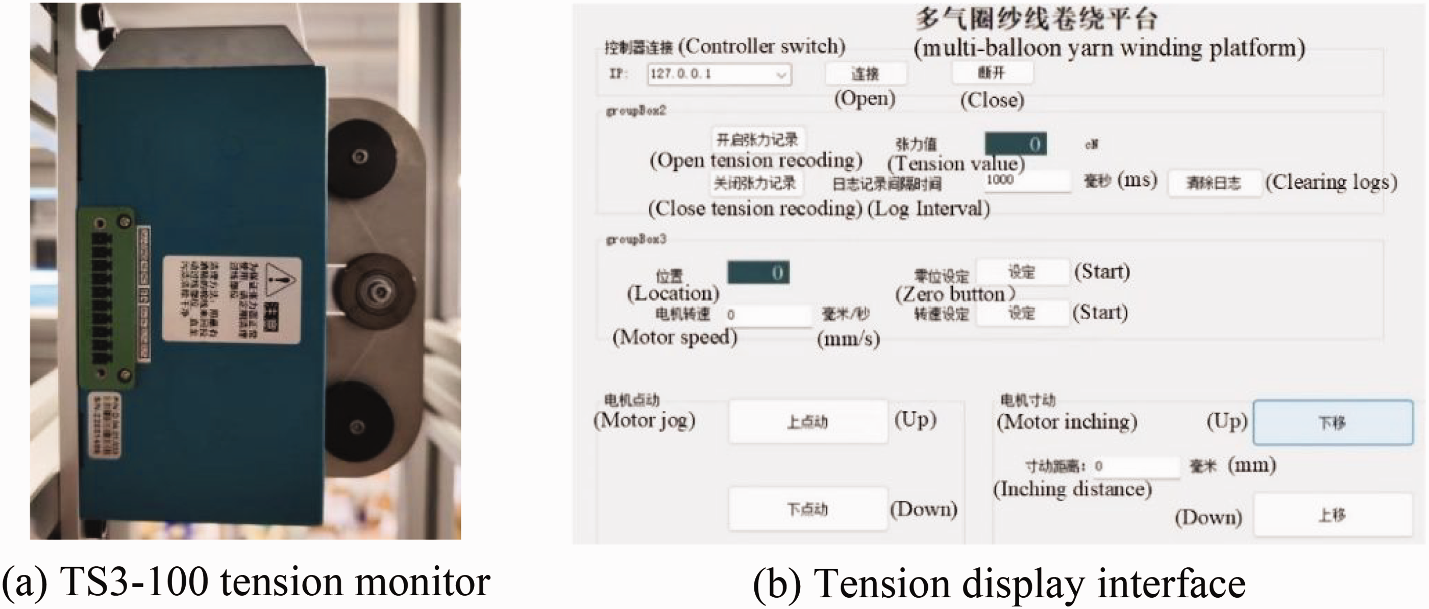
When monitoring the yarn tension at the top of the balloon, this experiment uses the TS3-100 tension monitor produced by Guangdong Tension Technology Co, Ltd. The instrument is shown in Figure 3-9.
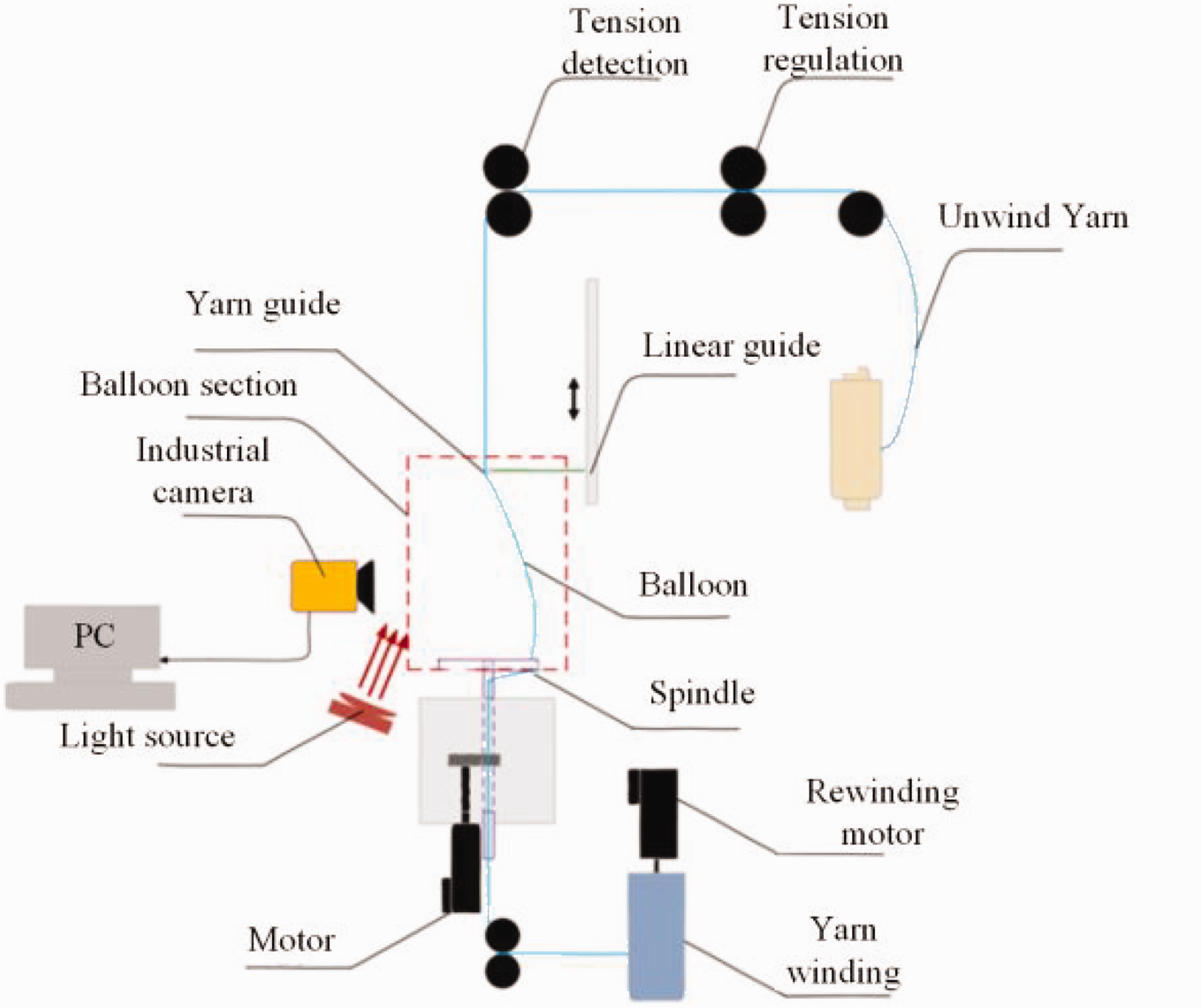
Design scheme of experimental device.
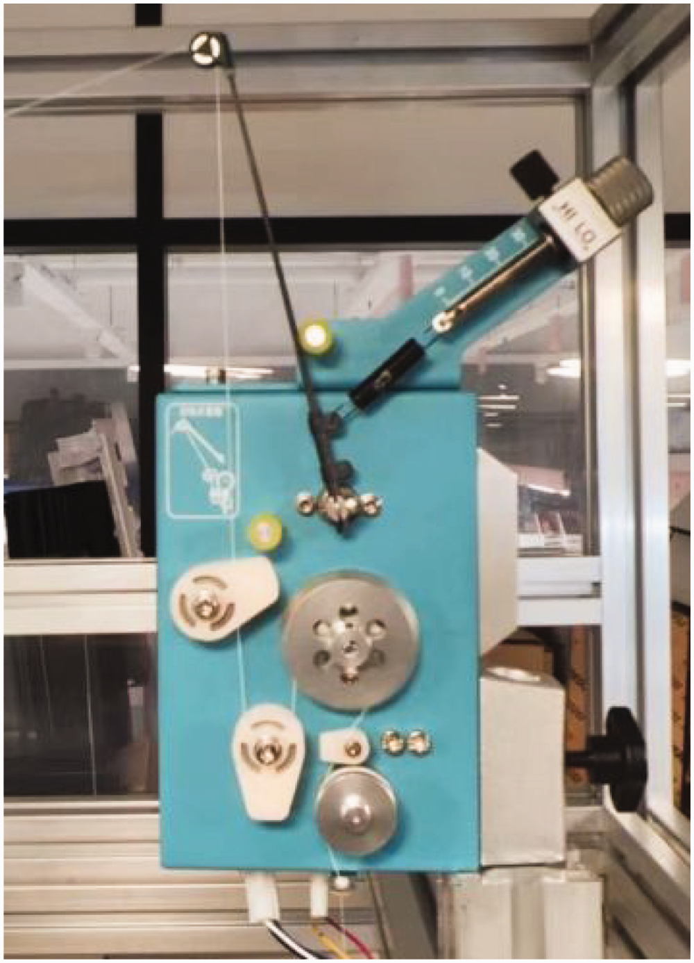
For the tension adjustment device, we selected the ETA-100L-R/RD electronic tensioner to adjust the yarn tension, thereby forming a steady-state yarn balloon. The ETA-100L-R/RD electronic tensioner is shown in Figure 3-10.

Specific experimental device.
In this experiment, the Daheng Image ME2P-2621-15U3C industrial camera and the matching Daheng Image HN-P-0628-6M-C1/1.8 lens were used to capture the balloon trajectory envelope profile. In the high-speed rotary module, the three-phase asynchronous motor drove the rotor to rotate at a high speed to form a balloon, and a stepping motor was used to control the up-and-down movement of the yarn guide, thereby facilitating the control of the height of the balloon. The entire simulation experiment platform is shown in Figure 3-11. Figure 3-12 describes the comparison process between the experiment and the simulation.

Yarn winding module.
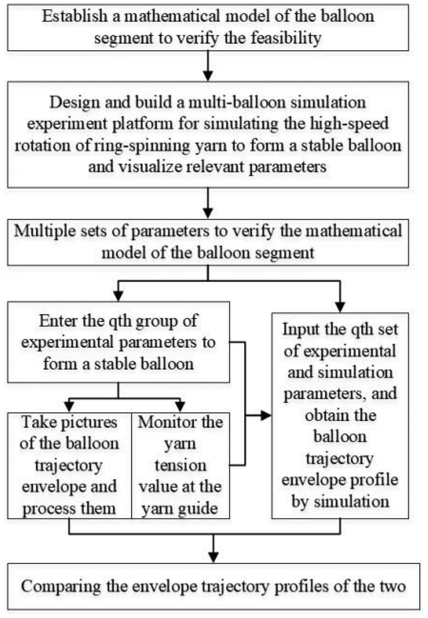
Technology roadmap.
After collecting the balloon trajectory envelope profile image, bilateral filtering,21,22 histogram equalization,
23
and Otsu threshold segmentation
24
were performed on the collected balloon trajectory envelope profile to obtain the pixel point coordinates of the balloon trajectory envelope profile.
25
Then it was converted into actual coordinates, and the balloon trajectory envelope profile extracted after image processing could be compared with the simulated balloon trajectory envelope profile.
Figure 3-13 shows the balloon trajectory envelope profile and simulation of the experimental platform built when the balloon height is 37 cm and the speed is 7000 r/min under the parameter conditions of Tables 1 and 2.
TS3-100 tension monitor and display interface. Figure 3-13 shows the balloon trajectory envelope profile and simulation of the experimental platform built when the balloon height is 37 cm and the speed is 9000 r/min under the parameter conditions of Tables 1 and 2. Figure 3-15 shows the balloon trajectory envelope profile and simulation of the experimental platform built when the balloon height is 37 cm and the speed is 11,000 r/min under the parameter conditions of Tables 1 and 2.
ETA-100L-R/RD electronic tensioner. Front view (left) and side view (right) of the experimental device. Figure 3-16 shows the balloon trajectory envelope profile and simulation of the experimental platform built when the balloon height is 37 cm and the speed is 12,000 r/min under the parameter conditions of Tables 1 and 2.
Schematic diagram of the way to compare the experimental and simulation results.
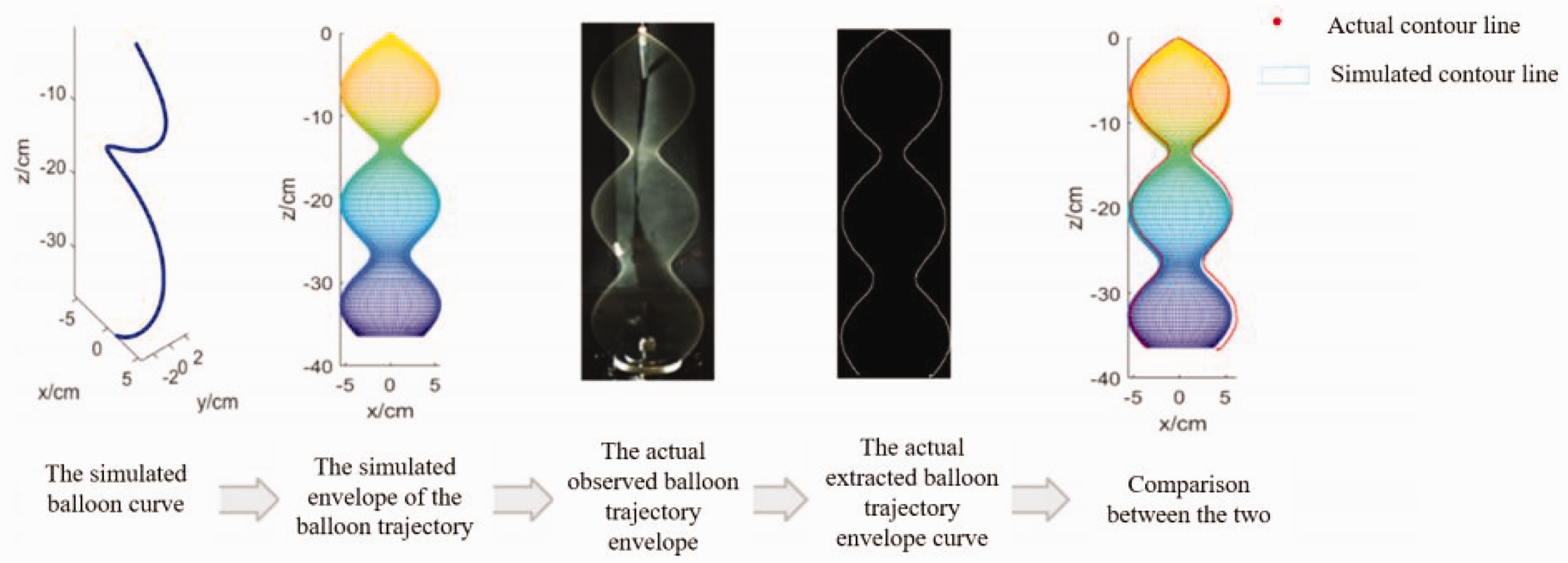
Through the above comparative analysis, it can be seen that the balloon trajectory envelope profile obtained by the experiment is relatively consistent with the balloon trajectory envelope contour obtained by simulation. Therefore, when the parameters are certain, the balloon shape can be qualitatively simulated by simulation. There are some differences between the simulation results and the experimental results, and the reasons are as follows:
Since the simulation assumes that the position of the yarn at the yarn guide is constrained, but in the actual process, the yarn rotates at a high speed in the extremely small inner hole of the yarn guide, which makes the comparison results different. Due to the ex-factory twist of the experimental sample 5s yarn is 40 twists/10 cm. During the experiment, the rotor drives the yarn to rotate to form an air circle, which makes the twist of the yarn larger than the twist of the factory, which in turn affects the linear density of the yarn, causing errors between the experimental results and the simulation results.
The relationship between yarn tension of the multi-balloon and balloon shape
Limited by the experimental platform and research time, this section discusses the relationship between yarn tension, balloon shape, spindle speed, and balloon height based on the multi-balloon simulation experiment platform and simulation. The effect of the yarn material and the radius of the bottom of the balloon (rotor cup) will not be discussed (it will be discussed in a follow-up article).
Analysis of the relationship between yarn tension and shape of the multi-balloon
Considering the safety of the experimental process and the consistency of the simulation, both in the experiment and the simulation we chose to discuss the influence of the spindle speed in the speed range of 7000–12,000 r/min. The range of balloon height was aimed at covering the existing balloon height of ring spinning and testing the ultra-high balloon height proposed by Spanish company, and the adjustable range of 17–63 cm was selected. The parameters of the yarn sample materials selected for the experiment are shown in Table 1. From the verification results in the third section, it can be seen that the simulation results are basically consistent with the experimental results. Therefore, in order to save the length of the article when discussing the relationship between yarn tension and balloon shape, we have only showed the balloon shape relationship obtained from the experiment and the simulation comparison conclusion diagram.
When the balloon height is 17 cm
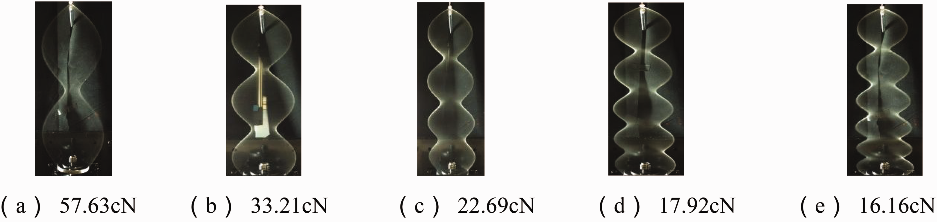
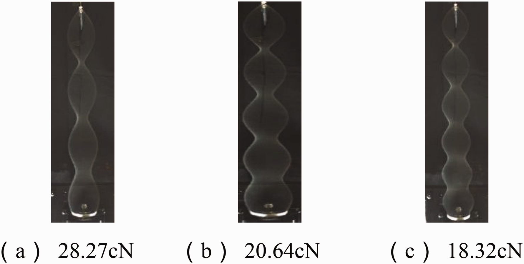
The stable balloon trajectory envelope profile and yarn tension at each spindle speed are shown in Figures 4-1 to 4–6.
When the height of the balloon is 17 cm, the relationship between the yarn tension of the balloon at different speeds and the number of balloon sections obtained through simulation is shown in Figure 4-7.
As shown in Figure 4-7, when the height of the balloon is 17 cm, the number of sections in the balloon ranges from one to two sections, and the increase in the spindle speed will increase the yarn tension at the yarn guide.
When the balloon height is 37 cm.
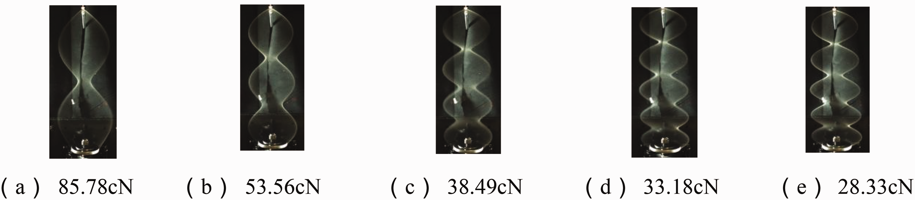
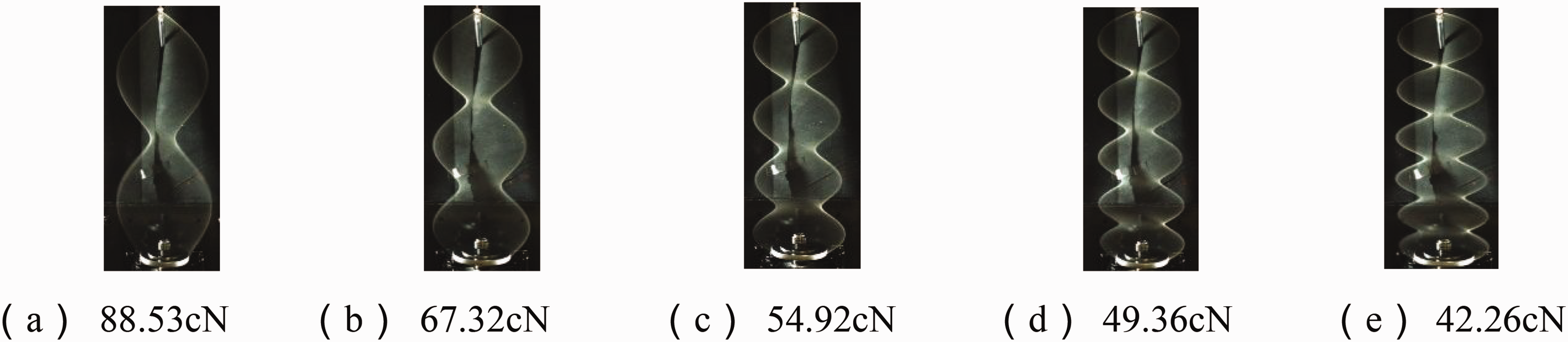
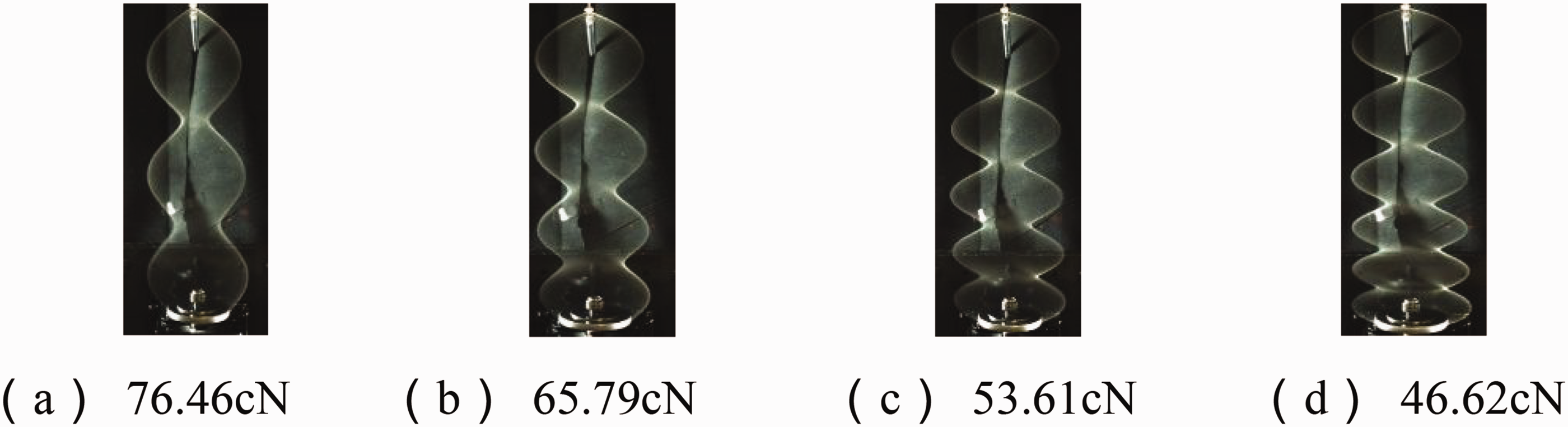
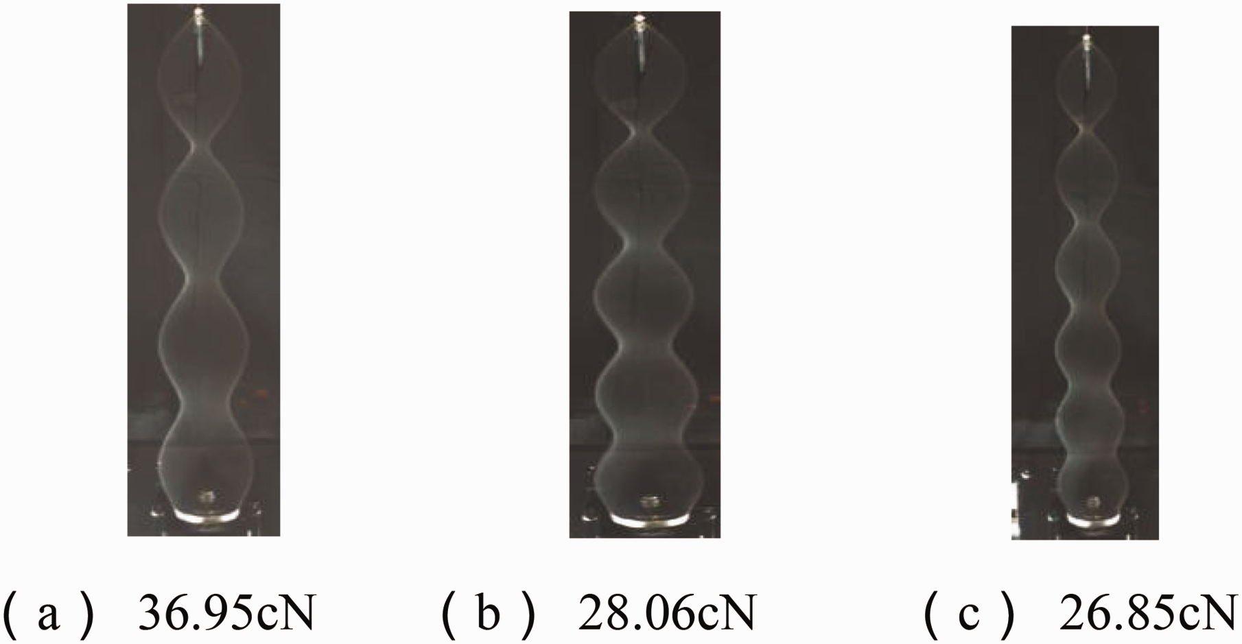
The stable balloon trajectory envelope profile and yarn tension at each spindle speed are shown in Figures 4-8 to 4-13.
When the height of the balloon is 37 cm, the relationship between the yarn tension of the balloon at different speeds and the number of balloon sections obtained through simulation is shown in Figure 4-14.
When the height of the circle is 37 cm, the number of balloon sections ranges from two to six sections, and the three pictures all show that the number of balloon sections increases, and the yarn tension at the yarn guide decreases significantly.
When the balloon height is 63 cm.
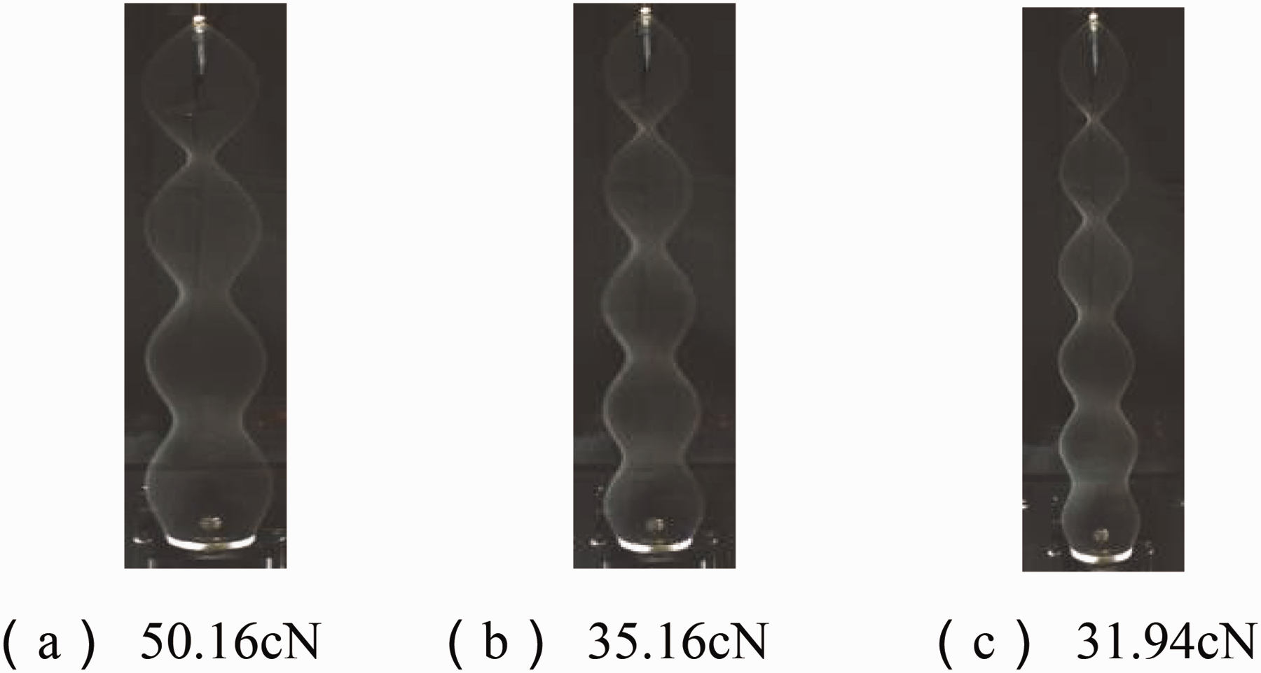
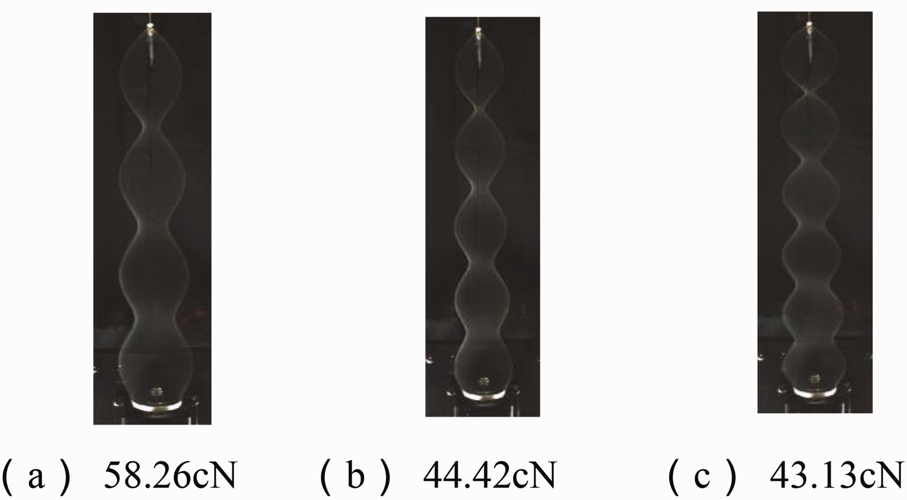
The stable balloon trajectory envelope profile and yarn tension at each spindle speed are shown in Figures 4-15 to 4–20:
When the height of the balloon is 63 cm, the relationship between the yarn tension of the balloon at different speeds and the number of balloon sections obtained through simulation is shown in Figure 4-21.
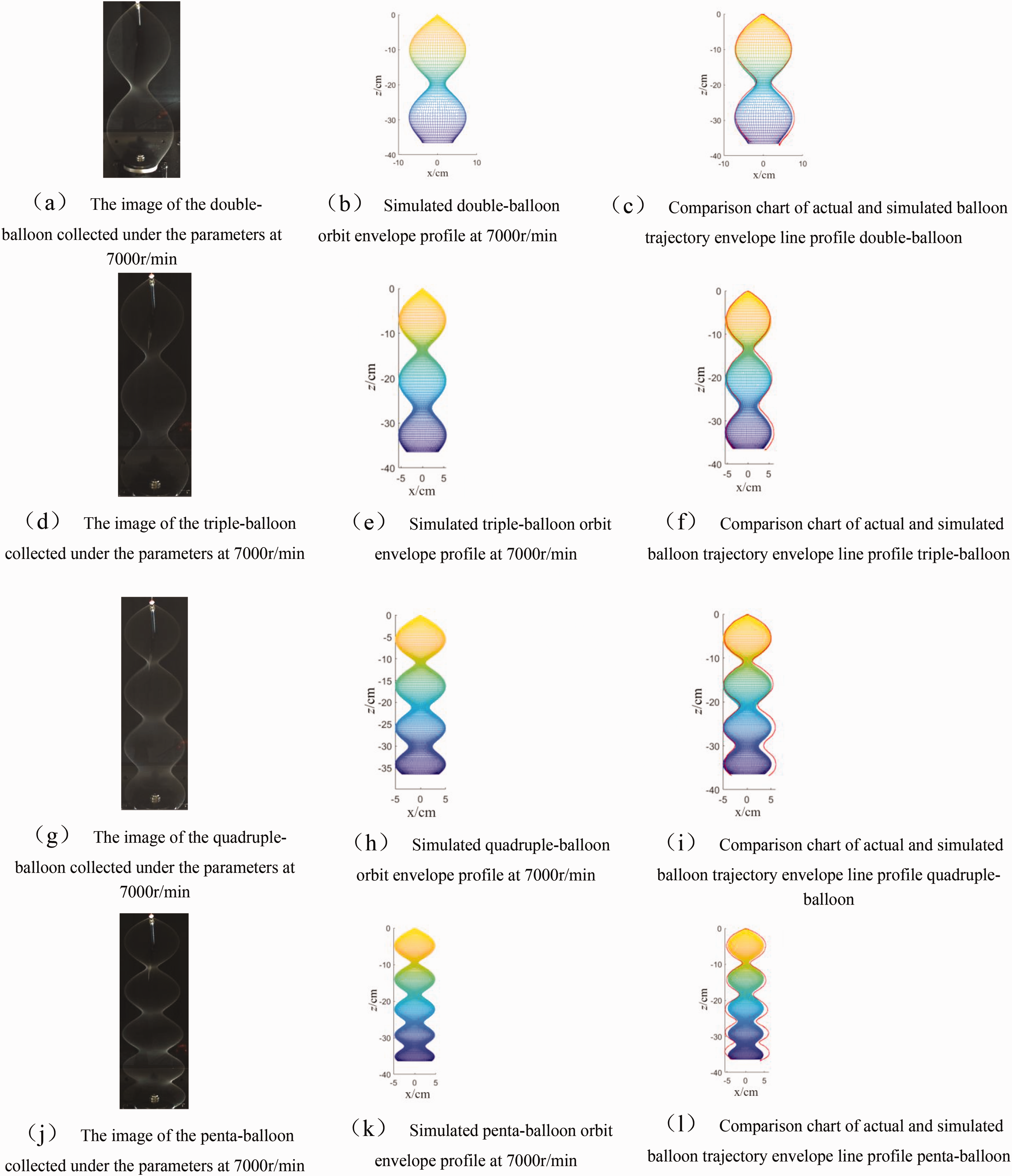
Experimental verification results under 7000 r/min parameter conditions.
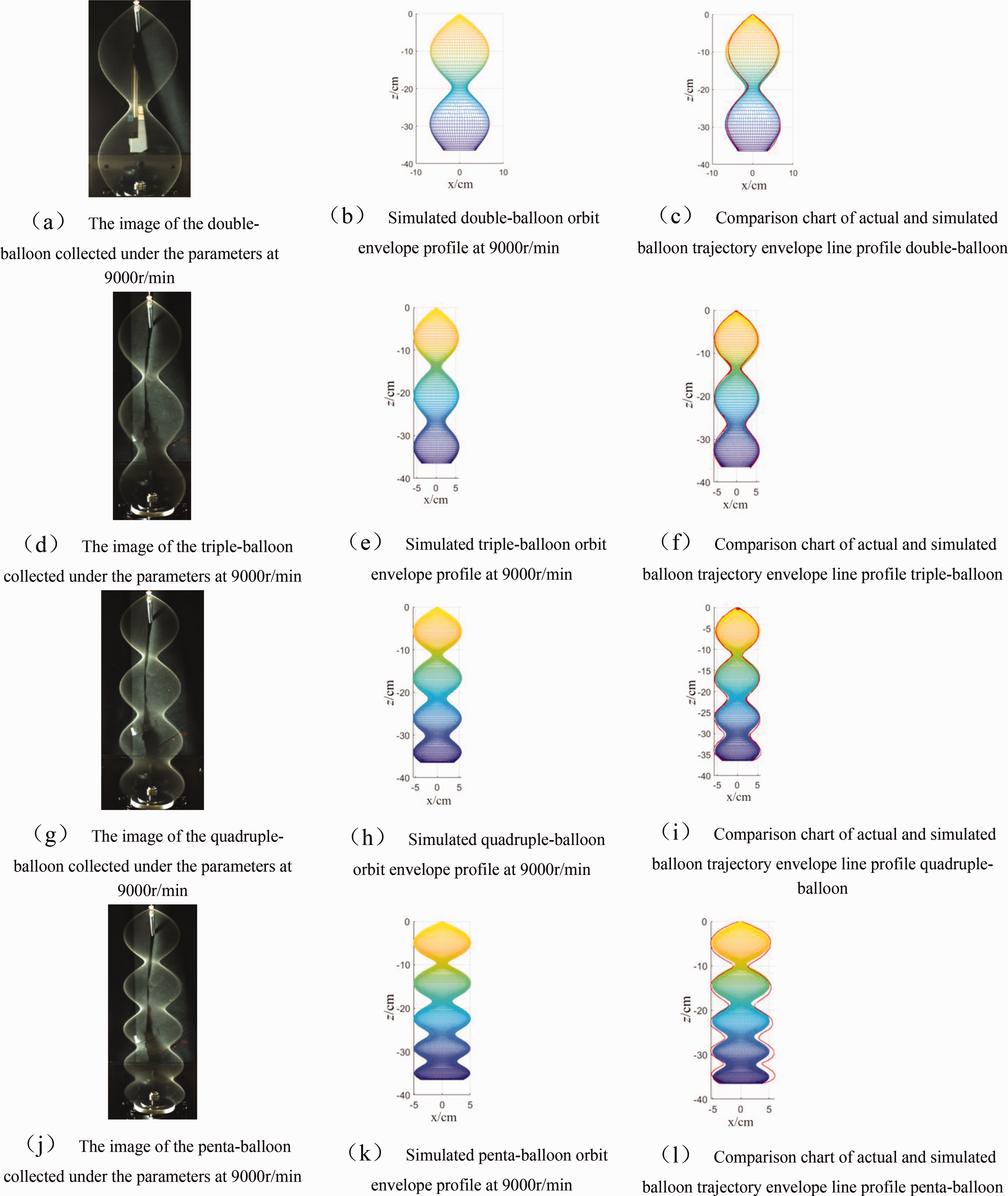
Experimental verification results under 9000 r/min parameter conditions.

Experimental verification results under 11,000 r/min parameter conditions.

Experimental verification results under 12,000 r/min parameter conditions.
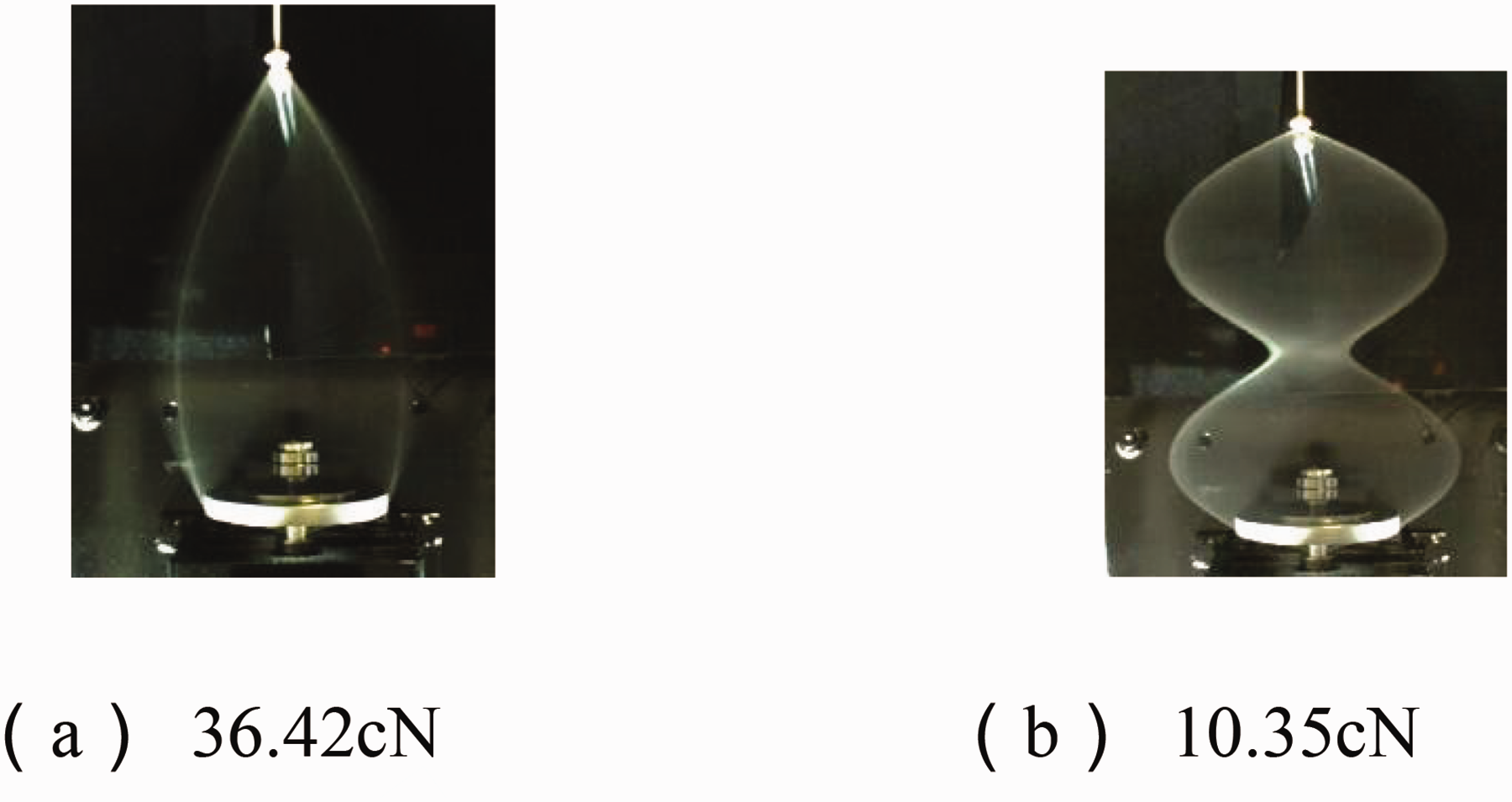
Balloon track envelope profile and yarn tension value when the balloon height is 17 cm and the speed is 7000 r/min.
Figure 4-21 shows that when the ring height is 63 cm, the number of balloon sections ranges from four to six sections, and it can be seen from the figure that when the number of balloon sections changes suddenly at different speeds, the changing trend of the yarn tension at the yarn guide is different, which also shows that the stability of the balloon is different under different numbers of sections.
Factors affecting yarn tension
From Figures 4-7, 4–14, and 4–21, it can be seen that:
When the number of balloon sections increases by one, the yarn tension at the top of the balloon decreases significantly. With the increase in the number of balloon sections, the reduction of the yarn tension at the top of the balloon tends to decrease. At the same spindle speed, the more the number of sections of the balloon, the tension range corresponding to the number of segments tends to decrease. When the number of balloon sections changes suddenly (such as the process of the sudden change from single-balloon to double-balloon, and from double-balloon to triple-balloon), the shape of the balloon changes, and the tension fluctuates greatly, which should be avoided in actual spinning. With the increase of the speed of the balloon, when the number of balloon sections is the same, the yarn tension at the top of the balloon (yarn guide) tends to increase. And at different speeds, the range of tension changes at the yarn guide for balloons with different numbers of sections is also different, so in the following, we will analyze the stability of multi-balloon at different speeds. As the height of the balloon increases, the number of sections of the balloon tends to increase. Under the same speed and number of sections of the balloon, the yarn tension at the yarn guide decreases with the increase of the height of the balloon.
Shape stability analysis of multiple-balloon
From the analysis above, it can be seen that the yarn tension at the top of the balloon will decrease as the number of balloon sections increases, and the tension fluctuation range of the balloon at the steady state of the section number tends to decrease. For example, under the parameter conditions of Tables 1 and 2, take the balloon height as 37 cm and the spindle speed as 8000 r/min as an example. Under this condition, the balloon is stable at a certain number of sections, and the tension range
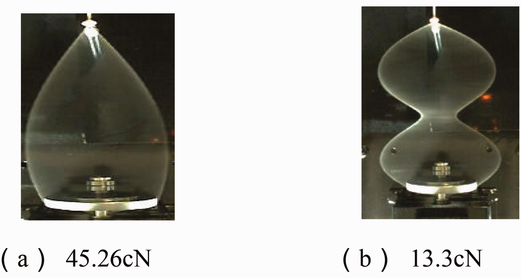
Balloon track envelope profile and yarn tension value when the balloon height is 17 cm and the speed is 8000 r/min.

Balloon track envelope profile and yarn tension value when the balloon height is 17 cm and the speed is 9000 r/min.

Balloon track envelope profile and yarn tension value when the balloon height is 17 cm and the speed is 10,000 r/min.

Balloon track envelope profile and yarn tension value when the balloon height is 17 cm and the speed is 11,000 r/min.

Balloon track envelope profile and yarn tension value when the balloon height is 17 cm and the speed is 12,000 r/min.

The relationship between the yarn tension at the top of the balloon and the number of balloon sections when the balloon height is 17 cm.
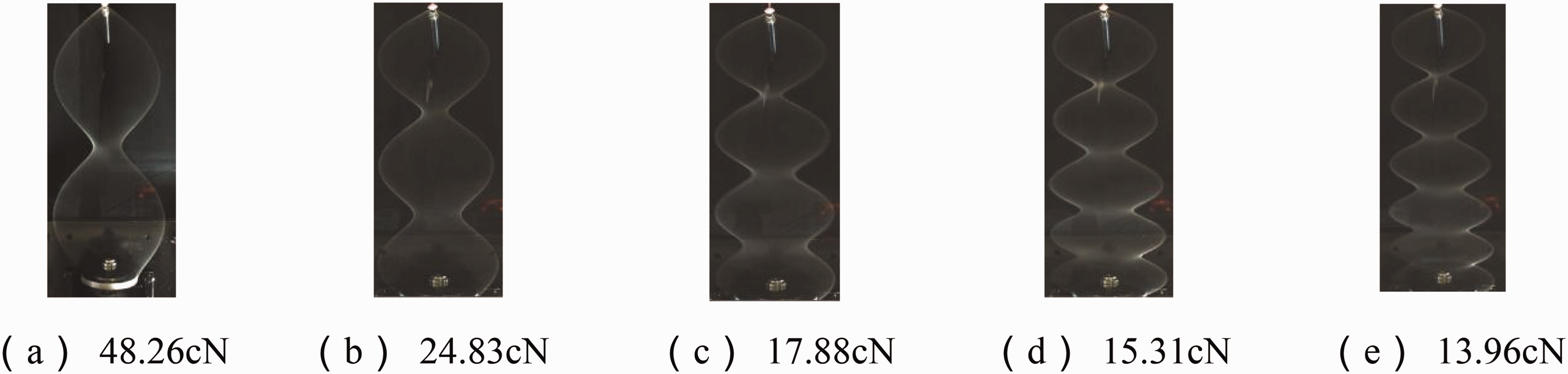
Balloon track envelope profile and yarn tension value when the balloon height is 37 cm and the speed is 7000 r/min.
Balloon track envelope profile and yarn tension value when the balloon height is 37 cm and the speed is 8000 r/min.

Balloon track envelope profile and yarn tension value when the balloon height is 37 cm and the speed is 9000 r/min.
Balloon track envelope profile and yarn tension value when the balloon height is 37 cm and the speed is 10,000 r/min.
Balloon track envelope profile and yarn tension value when the balloon height is 37 cm and the speed is 11,000 r/min.
Balloon track envelope profile and yarn tension value when the balloon height is 37 cm and the speed is 12,000 r/min.

The relationship between the yarn tension at the top of the balloon and the number of balloon sections when the balloon height is 37 cm.
Balloon track envelope profile and yarn tension value when the balloon height is 63 cm and the speed is 7000 r/min.
Balloon track envelope profile and yarn tension value when the balloon height is 63 cm and the speed is 8000 r/min.
Balloon track envelope profile and yarn tension value when the balloon height is 63 cm and the speed is 9000 r/min.
Balloon track envelope profile and yarn tension value when the balloon height is 63 cm and the speed is 10,000 r/min.

Balloon track envelope profile and yarn tension value when the balloon height is 63 cm and the speed is 11,000 r/min.
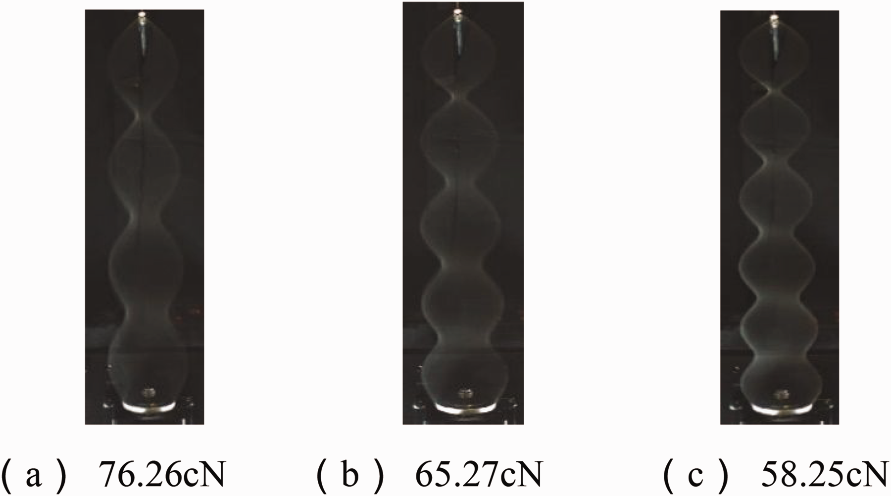
Balloon track envelope profile and yarn tension value when the balloon height is 63 cm and the speed is 12,000 r/min.
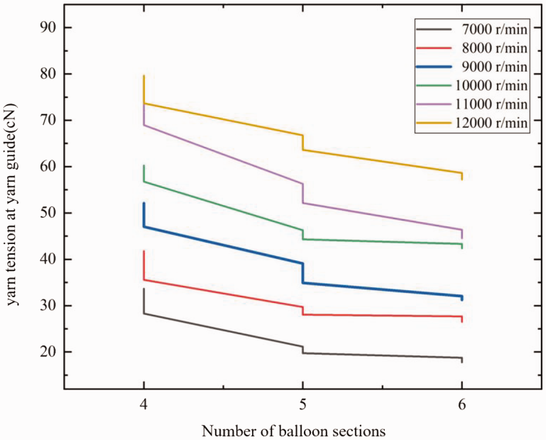
The relationship between the yarn tension at the top of the balloon and the number of balloon sections when the balloon height is 63 cm.
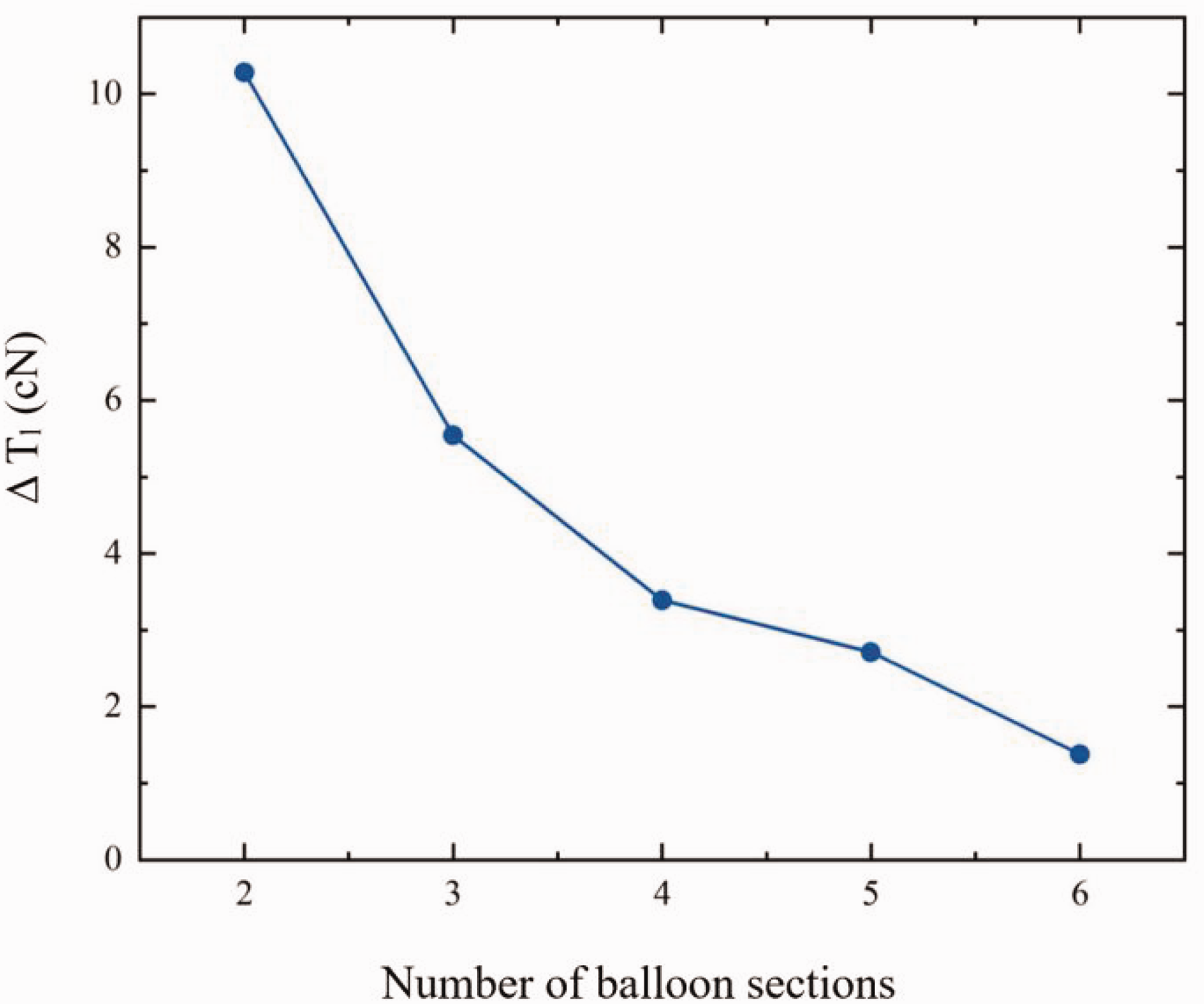
The relationship between the yarn tension range and the number of balloon sections without a sudden change in the number of sections.
In the actual process, the balloon formed by spinning is generally in a steady state, and too large or too small yarn tension will affect the yarn quality. Therefore, it is not possible to increase the number of balloon sections blindly because of the need to reduce the yarn tension, to reduce the stability of the balloon shape, and the yarn tension and the balloon shape should be within a reasonable range. It can be seen from Figures 4-1 to 4 –22 that, under the parameter conditions of Tables 1 and 2, when the balloon height is 17 cm and the spindle speed is 7000–11,000 r/min, choosing single-balloon spinning yarn is more reasonable. It is more reasonable to choose double-balloon spinning when the spindle speed is 11,000–12,000 r/min. When the balloon height is 37 cm and the spindle speed is 7000–8000 r/min, it is more reasonable to choose triple-balloon spinning. It is more reasonable to choose quadruple-balloon spinning when the spindle speed is 8000–10,000 r/min, and it is more reasonable to choose penta-balloon spinning when the spindle speed is 10,000–12,000 r/min. When the balloon height is 63 cm, it is more reasonable to choose quadruple-balloon spinning when the spindle speed is 7000–10,000 r/min, and it is more reasonable to choose penta-balloon spinning when the spindle speed is 10,000–12,000 r/min.
Conclusion
Based on the research background of the balloon phenomenon in the process of ring spinning, this article discusses the influence of spindle speed and yarn balloon height on balloon shape, balloon yarn tension, and the number of balloon sections. This article is summarized as follows:
The derivation of the mathematical model of the steady-state balloon section of the yarn is expounded. The fourth-order Runge-Kutta method is used to establish a mathematical model of the steady-state balloon section that ignores gravity. The corresponding boundary conditions and solution methods are given. After the validity of the mathematical model is verified by designing and building a multi-balloon spinning experimental platform, the relationship between the shape of the multi-balloon and the yarn tension is discussed by combining experiments and simulations. It was also found that the increase in the number of balloon sections will reduce the yarn tension, and changes in spindle speed and balloon height will also affect the relationship between yarn tension and balloon shape. Finally, through analysis, we found the corresponding balloon height and yarn speed when the balloon is in a steady state under a certain number of balloon sections.
The results of these experiments and simulations provide a clear data reference for the reduction of yarn tension in the existing ring spinning, effectively reducing the improvement of spinning quality and spinning efficiency. At the same time, the method of researching the reduction of yarn tension is given, and some theoretical parameters are provided as a reference for improving the process parameters of the ring spinning machine and the mechanical design of the spinning machine. But it is not better to blindly pursue low tension. Instead, it is necessary to find a suitable tension for spinning under the trend of continuous increase in spindle speed and even to maintain the original relatively low spinning tension. In the future, our team will conduct research on actual ring-spinning machines to enable more effective utilization in the field of industrial production.
Footnotes
Declaration of conflicting interests
The authors declared no potential conflicts of interest with respect to the research, authorship, and/or publication of this article.
Funding
The authors disclosed receipt of the following financial support for the research, authorship, and/or publication of this article: This work was supported by the Fundamental Research Funds for the Central Universities (grant numbers 2232023G-05-1).
