
Abstract
This paper presents a hybridized standalone electric vehicle (EV) design using hybrid energy storage system to solve the critical transportation issues in a grid-constrained environment, such as the city of Namibia. The suggested system integrates onboard regenerative braking and solar photovoltaic arrays of 3 kW (peak) to serve as the grid independent and obtain the substantial values of energy efficiency. This entails an innovative hybrid energy storage design, which combines both lithium-ion batteries and ultracapacitors banks where both the battery and the ultracapacitors can optimally store charge, with the battery to sustain the main power supply, and ultracapacitors to manages the peak loads on transient events such as acceleration and regenerative braking. The design uses automatic changeover system control in which it gives preference to the supply of solar and smooth integration of recovered kinetic energy in deceleration. Simulation findings indicate that the solar photovoltaic can supply about 25% of the daily energy demand, and the hybrid storage approach receives regenerative braking recovery rates of 20–25% in intercity cycles, which is far greater than the normal EV performance of 10–15%. The ultracapacitor subsystem can be charged 60–80% state-of-charge during an event of braking; this helps a great deal in relieving strain of battery by far over 2000 cycles. The comparative analysis indicates a high battery to wheel efficiency of 85% to 90%, low energy costs (0.19 NAD/km) than the traditional plug-in hybrid vehicles. Climate-adaptive building offers sustainable mobility with economic and energy benefits.
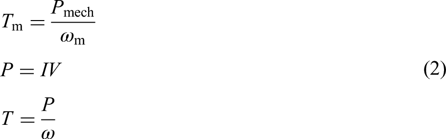
Keywords
Introduction
Electric vehicles (EVs) have become an essential part of the solution to the reduction of carbon footprint and the reliance on fossil fuels as the world transitions to sustainable transportation networks. In the meantime, EVs are heavily reliant on the existence of important infrastructure like charging terminals (Das et al., 2020), repair facilities (Savari et al., 2023), technical know-how (Mohammed et al., 2024), and so forth. Generally, the extensive use of EVs is determined by the performance of the vehicles and the accessibility of efficient and reliable charging systems. Electric car chargers are a significant element in the shift towards cleaner mobility because they enable the supply of the energy needed to power EVs in a convenient and efficient manner. The EV charging technology has been developed over the years to include home-based chargers to high-power public fast-charging stations (Farhadi and Moghaddas Tafreshi, 2022; Ilahi et al., 2023). The latest technologies, including smart charging (Meng et al., 2025), bidirectional power flows, and ultra-fast direct current (DC) charging, implemented on a printed circuit board (PCB) (Obe et al., 2020), are revolutionizing the EV technology integration with the power grid, hence improving the convenience of the user and grid stability. Nonetheless, some of the major challenges of EVs are managing grid impact (Judge et al., 2022; Saklani et al., 2024), the scarcity of charging points (He et al., 2025), and technicality/expertise (Noel et al., 2020). With the EV market still expanding, it will be necessary to overcome these obstacles to develop a smooth and effective charging system.
Namibia, the driest country in southern Africa, receives the least rainfall due to its arid climate and high evaporation rates. In this case, an alternative power source is mandatory, particularly with a unstable grid power supply to operate EVs effectively (Amupolo et al., 2022). The unreliable power supply and few charging stations in the country mean that only a self-powered charging system can be an environmentally friendly and affordable solution. Therefore, a standalone EV battery charger is one of the solutions that can be used to reduce the reliance on the national grid. This is especially important in the urban and rural regions where grid connectivity is uneconomical or unavailable (Chen et al., 2025). Also, energy storage systems can be used to complement the functionality of these standalone chargers to increase reliability such that EV users can always access power despite the state of the grid (Badrudeen et al., 2024a). With the implementation of these solutions, Namibia will be able to speed up the process of switching to cleaner transportation, become less dependent on fossil fuels, and contribute to planet sustainability efforts. But to realize a successful standalone charger, there are several technical issues that need to be addressed, such as how to efficiently manage power, how to efficiently convert energy and maintain system stability under load and environmental variations, which are considered here. To this effect, an independent EV battery charger linked to a DC bus terminal will play a significant role in the transport sector of Namibia by making the EV charging infrastructure more accessible and efficient. Compared to traditional single-phase charging systems (Dini et al., 2023; Gao et al., 2020), a multi-DC bus system will be more efficient and stable, decreasing downtime for EV users and making electric mobility more feasible in both personal and commercial settings. This has especially been useful to the public transport services, including electric buses and taxis, which must have short turnaround times to ensure they are efficient in their operations. By having a well-spread network of independent DC link chargers, the transport system in Namibia will be able to move towards greener, more reliable, and cost-efficient mobility services, which will promote the growth of the economy and minimize the amount of environmental due to traditional transport systems and their fuel consumption. The objective of this research is to (1) minimize the cost of fuel used in transportation, (2) reduce the environmental pollution, and (3) improve power utilization and maintain a better power factor. The remainder of the paper is structured as follows: the second section provides a background on the related literature. The third section describes the methodology and system configurations. In the fourth section, the results and analysis of simulation is presented. The discussion and conclusion are presented in the next section 5, alongside with the limitations and challenges in this work. Finally, the last section presents the recommendations.
Literature review
EVs are gaining popularity across the world as an alternative to transportation powered by fossil fuels. This shift is creating new innovations in the charging infrastructure, including hybrid standalone topologies containing DC link battery chargers. Such systems would be particularly appropriate in places such as Namibia that have less power infrastructure, and which require fast charging (Geiriseb and Dumba, 2025; Shahed and Rashid, 2024). The battery chargers are also advancing academically and technologically, with the government policies in line with encouraging alternative energy sources further accelerating this aspect (Hemavathi and Shinisha, 2022). The essence of a standalone EV topology including a DC link battery charger is to allow the management of energy, the reduction of the grid reliance, and the improvement of the flexibility of charging operations. Studies often focus on the case of a standalone EV system, which takes advantage of renewable energy sources (solar and wind) to address energy access problems in developing nations (Schetinger et al., 2020). The design involves energy storage and high-quality power electronics converters that enhance the general reliability and efficiency of the output power (Li et al., 2024). One of the key elements includes a DC bus battery charger that enables unidirectional movement of power and enables EVs to act both as consumers and generators of power (Acharige et al., 2023).
The situation in Namibia, where an interconnected grid is uncommon, standalone EV charging is an effective solution for achieving adequate and versatile mobility. Photovoltaic (PV)-charging stations provide a feasible solution to the EV infrastructure expansion with its rich sun resources (Oladigbolu et al., 2023). Research proves that standalone charging with the use of PV can improve energy security and decrease the use of fossil fuels (Fathabadi, 2020; Yang et al., 2021). The introduction of DC bus chargers into this system can also contribute to the decentralization of energy, efficiency, and decreasing the duration of charging. The development of battery charging technology indicates the significance of power electronics in the creation of high efficiency and speed in charging. Intertwined converters are used in bus link charging systems and have advantages such as reduced ripple currents, better thermal performance, and increased reliability (Leal et al., 2023). Such benefits are essential to Namibia, where the EV uptake is still young and needs a robust yet convenient system to charge it. It is also emphasized that implementation of smart charging systems will allow optimizing the delivery of energy, lowering the influence on the grid, and increasing the utility of independent stations (Badrudeen et al., 2024b; Lu et al., 2025).
The viability of this topology implementation to Namibia is influenced by the cost, energy storage option, and location of strategic stations. The research on lithium-ion battery technology proves that the combination of storage and renewables will enhance the stability of EV charging infrastructure notably (Al Wahedi and Bicer, 2020). Moreover, DC link chargers which connect to PV arrays and regenerative braking systems allow better control of the battery extending battery life and minimizing maintenance (Mazumdar et al., 2024). The emerging sustainable energy policies in Namibia are in line with the long-term environmental and economic advantages of the solutions.
There are other areas with the same energy challenges that show the success of standalone EV charging in the form of case studies. As an example, off-grid solar-powered EV stations in sub-Saharan Africa have confirmed the technical and economic benefits of integrating standalone structures with DC bus chargers (Turan et al., 2025). The lessons gained in these experiences are useful to Namibia in building a robust EV ecosystem. Regulation systems and policies can also play a significant role in the adoption of EVs. Studies have shown that incentives provided by the government, strategic investment, and public–private partnerships are very crucial in accelerating such a transition (Pinilla-De La Cruz et al., 2022; Tirunagari et al., 2022). The policies that are planned in Namibia to support standalone charging stations and incorporate EVs into the national approach to transport can contribute to the transition to the sustainable mobility considerably.
Technically, there have been suggested different designs of integrated chargers typically depending on the type of motor. In the case of common two-phase motors, such solutions as boost rectifiers can be necessary to overcome access to windings in a motor or reconfiguring through contactors during charging (Ali et al., 2023). Although multi-phase motors have advantages including the elimination of the problem of torque production, there are no such motors in EVs now, which constrains their use. The design of control systems of such chargers is usually aimed at reducing total harmonic distortion (THD) to the lowest possible and working at close to unity power factor. The control approaches include proportional–integral (PI) compensators, and more complicated control approaches, such as model predictive control, but the latter is often challenging to execute (Harbi et al., 2023). PI compensators are widespread but may lack robustness due to their sensitivity to circuit parameter variations (Norouzi et al., 2021).
In summary, the integrated standalone EV topology with DC link battery chargers is one of the solutions that could be offered to the Namibian transport needs. Namibia can use its huge solar potential and improved charging solutions to create a strong and sustainable EV network. Existing literature shows that DC link battery charging is efficient, reliable, and scalable. Going forward, Namibia will need more studies on cost optimization, complementary policy frameworks, and technical implementation of the successful standalone EV charging implementation.
Proposed methodology
Hybrid EV architecture
A standalone hybrid electric vehicle (S-HEV), proposed in Figure 1, has two main sources of power: a solar PV and regenerative braking that supply the common DC bus through an automatic change-over controller unit. Each source has one dedicated converter interface, which is connected to the DC link of 400–450 V nominal value, through an automatic change-over switch (ACOS) or a multi-input DC–DC converter. The ACOS prioritizes the use of solar input, when present, to recharge the energy storage, with braking events switching permanent magnet synchronous motor (PMSM)-generated energy to storage.
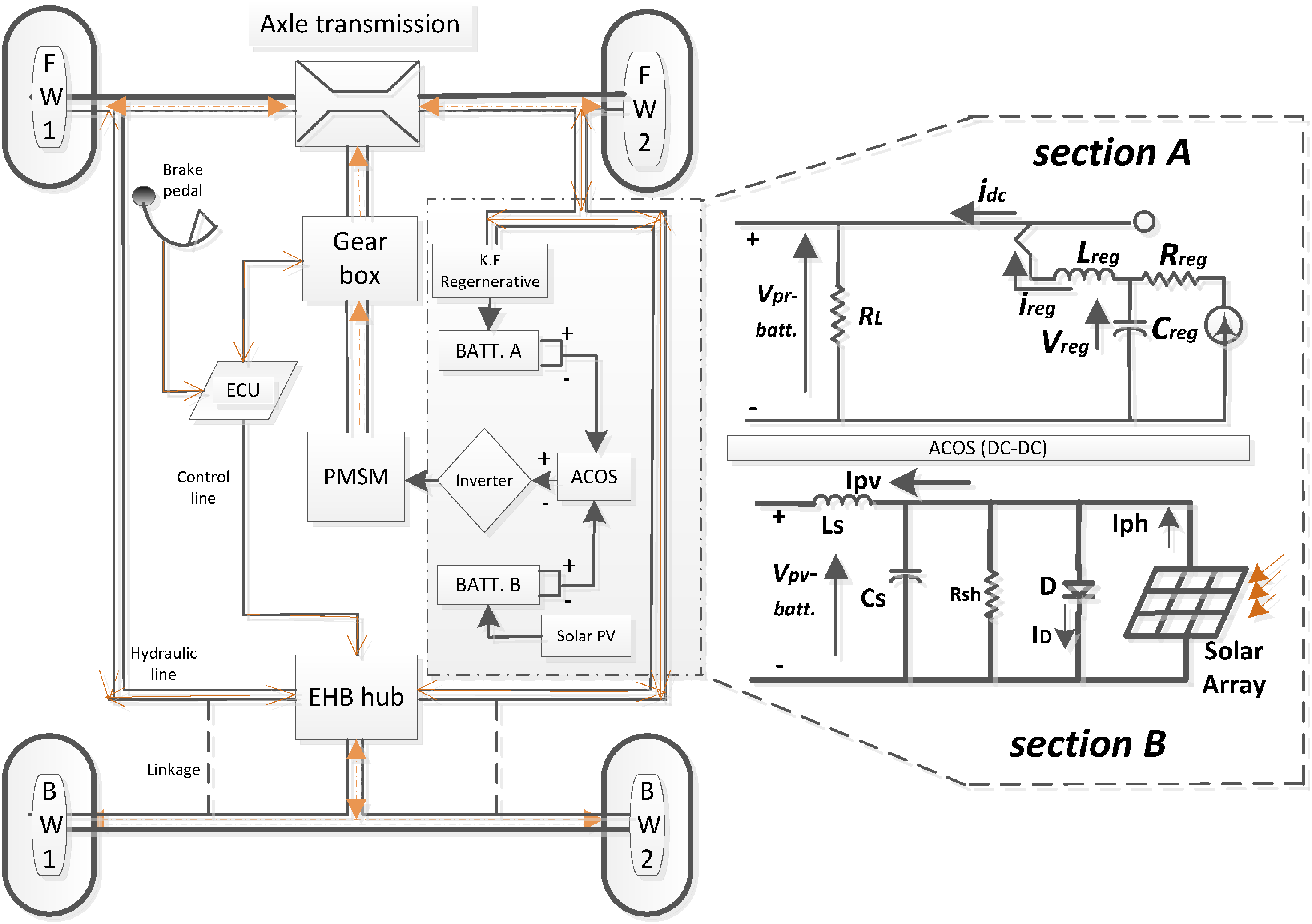
Schematic of the proposed hybrid electric vehicle configuration.
As a measure to ensure daily supply of energy, the system incorporates auxiliary energy storage devices that take in and store surplus solar and regenerative energy when they are being produced in excess quantities. This backup power is used at night or any other time of low sunlight to maintain consistent vehicle operation in all day transportation service. The main battery bank is logically divided into two modules (one from PV, the other from regenerative braking) and can be operated in parallel or independently, which provides flexibility in energy management. PV-charged module can be isolated when one module is in active charge to prevent overcharging. This off-grid system, which is entirely powered by renewable sources (sunlight and kinetic recovery) and aided by an auxiliary storage, offers a sustainable and fuel-free option for continuous vehicle propulsion. A battery bank, combined with an ultracapacitor (UC), buffers the DC link. This link feeds the three-phase inverter, which powers the PMSM to drive the wheel.
The auxiliary energy savings is capable to use the excess stored energy to power vehicle systems during idle conditions. During motoring, the PMSM is supplied by the DC link, which is powered by the battery as the primary source and the UC as the second line of defence, respectively. Motor drive is a very powerful and lightweight purpose-built PMSM that can operate bi-directionally, which means it can accomplish forward and reverse motoring and regenerative generation. The fixed gear ratio transmits the torque to the front wheel (
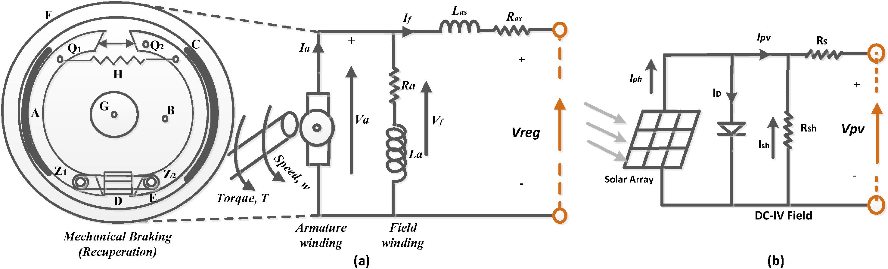
Schematics of the primary energy harvesting sub-systems: (a) regenerative braking energy recovery circuit and (b) solar photovoltaic charging system.
Solar PV sub-system
The PV array on the vehicle body is modelled as a single-diode model with photo-current source, diode, and series/shunt resistors. To simulate, we consider a low-cost PV array with a rated power of 3.0 kW peak under standard test conditions (1000 w/
Technical data analysis of the proposed vehicle, solar, and regenerative braking.
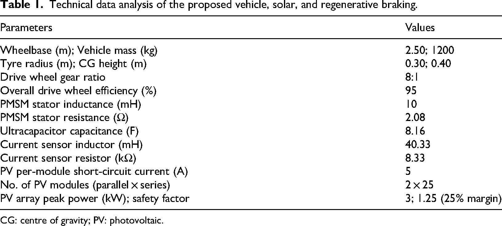
CG: centre of gravity; PV: photovoltaic.
Regenerative braking sub-system
Figure 2(a) shows the energy recovery circuit of regenerative braking. When the vehicle is decelerating, the PMSM is used in a generating mode channelling the kinetic energy in the wheels to generate electricity which could be inputted into the battery of the vehicle. In design, the energy is captured by a 400 V battery bank (200 V deep-cycle battery modules in series), and a high capacitance is used to smooth out the power surges. When braking, the back-electromotive force of the motor increases with respect to the wheel speed of approximately 33.6 rad/s (320 r/min, a moderate urban speed) the PMSM can provide 333–375 V. The current is sent to the storage elements through semiconductor, insulated gate bipolar transistor/metallic oxide semiconductor field effect transistor switches. Torque at the wheel is

The PMSM and braking system are tuned so that most braking events, especially downhill or moderate stops, are handled electrically, with mechanical brakes as backup for hard stops or low-speed hold. This not only recovers energy but also reduces wear on the brake pads and discs, thus improving overall vehicle durability (Table 2).
Prototype PMSM and the inverter specification.
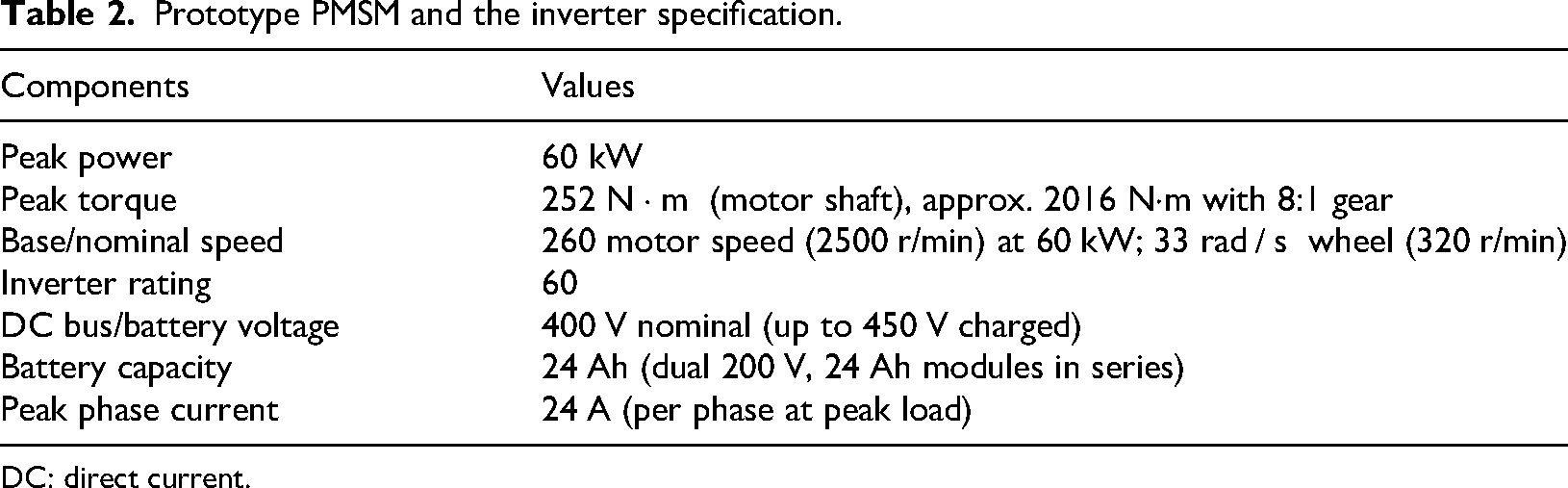
DC: direct current.
The system power flow and the force analysis
To optimize performance and manage friction, the brakes work in conjunction with the electric propulsion system without compromising vehicle safety, with no degradation of the driving vehicle safety, and therefore necessitated some force calculations. The hybrid aspect of such function (multi-port) as outlined in Figure 3, as part of the converter model as discussed in Eya et al. (2023) and Zhang et al. (2022), shows the various power storage mechanisms and the automatic change-over to alternative energy sources and this would comprise the solar, UC, and recuperative supply. The batteries get controlled by voltage at a rated value to yield optimum drivers at the inverter gating signal that provides alternating current (AC) power to drive the PMSM.
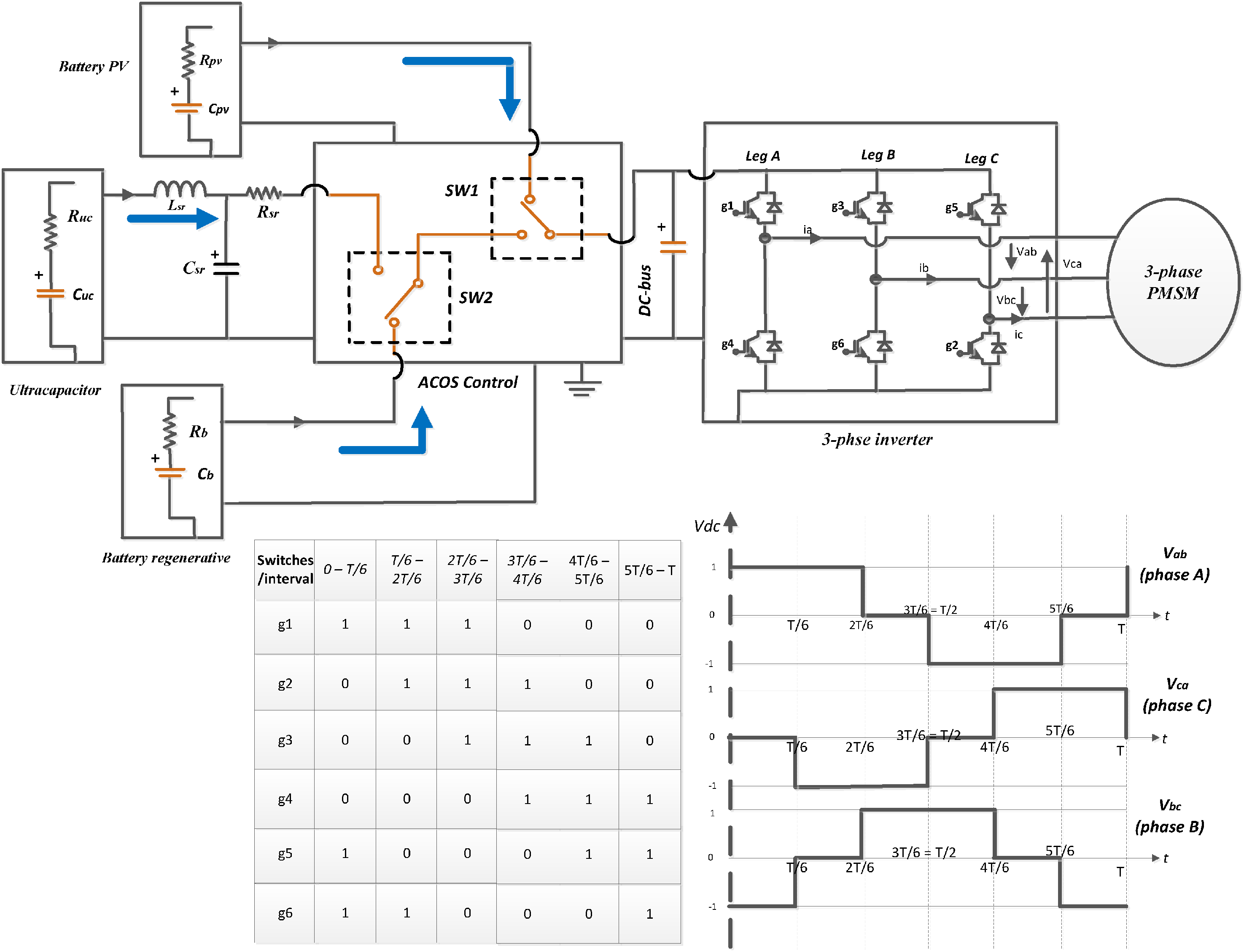
Hybrid system showing power flow and ACOS, with traditional inverter. ACOS: automatic change-over switch.
To allow the directional stability of the vehicle to be sustained, and at the same time to advance to optimum braking efficiency, the braking should be so balanced relative to the temporary loads on any one of the wheels on the axle. Several devices that restrict braking force of the rear wheels are applied such that the maximum amount of tyre–road adhesion is employed as it is observed in the literature studies.
The torque and the system of forces that acts on the vehicle as the vehicle is braked are shown in Figure 4, where the resultant of the braking and inertia is proportional to the deceleration (negative acceleration) of the vehicle being acted on. The weight of the vehicle is counterbalanced by the vertical reaction forces 
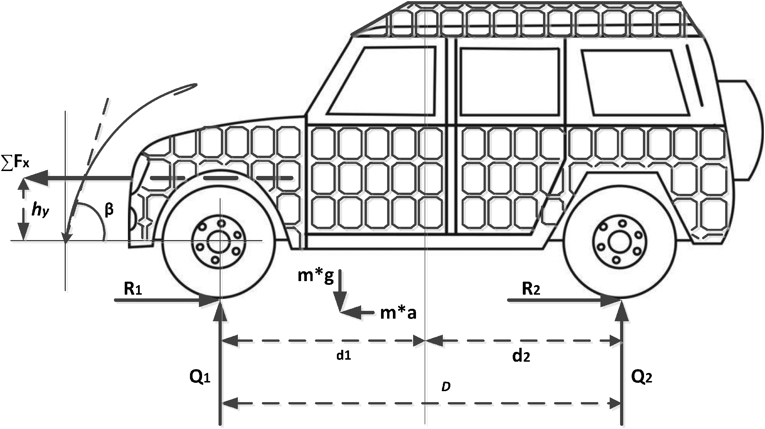
Schematic of the proposed EV showing applied forces during acceleration/braking. EV: electric vehicle.
Substituting equation (4ii) into (4i), which represents the horizontal force acting at the tyre–road contact point, yields: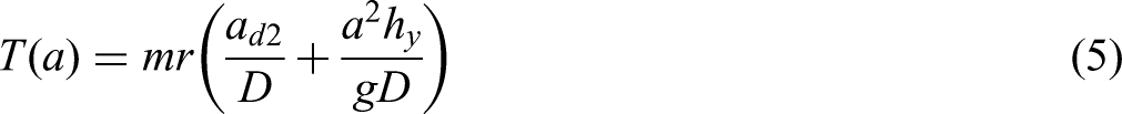
To bring the torque on the driving (front) axle wheels into a similar domain to the torque provided by the electric motor during the purely electrodynamic braking, it is proposed that the torque be multiplied by the efficiency ratio and divided by the gear ratio of the power transmission system which generates:
Hybrid energy storage
The storage system is a lithium-ion battery bank with a high-power UC added to it. The battery supplies most of the energy to drive the system continuously, and the UC deals with fast transients. The battery in our prototype design has a nominal 400 V and can deliver 12 A peaks and hence 4.8 kW output, enough to power a small city EV or a scaled down version. An example is a bank of 148 UC cells in series (2.7 V, 500 F) for 400 V, 3.38 F typically a DC–DC converter is used to interface it to the 400 V bus to handle the voltage differences. In our simulation, the UC bank had a capacity to provide short bursts of up to 12 A, and it was able to charge 60–80% state-of-charge (SOC) in a few minutes of regenerative events. The features of every energy source in the system are summarized in Table 1.
The efficiency of the battery considers the internal resistance of the battery and the partial charge/discharge losses during driving, but the UC efficiency is extremely high (95% or more) due to the short pulse that the UC can deliver and most of the losses can be attributed to the DC–DC converter and the heating of the equivalent series resistance. As can be observed, the PV system can provide a significant portion of the energy, up to 25% of the total in sunny days, which effectively increases the driving range by that margin. The UC has a small portion of the energy share but is significant in supporting power; it takes care of the peak loads and regenerative surges that would otherwise overload the battery. This hybrid storage solution is being used in the recent trends in the design of EVs that focus on integrating energy devices to maximize their complementary advantages.
Auxiliary power-saving feature
A key improvement in our system is the auxiliary mode that utilizes excess power. Under traditional EV operation, any solar energy generation during parking or light-load cruising may not be immediately consumed, and the regenerative opportunities are restricted to braking applications. We have designed it in such a way that surplus energy generated when the vehicle is active is stored and been used later when the vehicle is idle. This is achieved through the energy management controller in the ACOS/DC–DC unit, which keeps track of the SOC of the battery and UC, and the power requirement of vehicle's auxiliary loads such as lighting, high voltage alternate current (HVAC), and infotainment. In case the PV generates more energy than the traction system requires (during steady low power cruise in midday sun), the excess current is used to either charge the battery to a high SOC or recharge the UC. When the main battery has been charged to a safe high SOC (95%), any additional overcharge can be fed into an auxiliary storage reservoir or directly to auxiliary loads. In our application, the UC will act as a high-speed buffer of any overage; a small secondary battery or the 12 V accessory battery in a car could be added, which would be trickle charged by the main bus when excess power is present.
Energy is stored during idle time in the vehicle (especially at night) and may be used in either of the following two applications: (1) to directly drive on-board auxiliary systems and (2) to pre-condition the vehicle for the subsequent use. The system may operate a ventilation fan or cooling pump using the solar energy stored to maintain the cabin and battery within perfect temperatures when parked in the sunshine, instead of allowing it to heat up and later using battery power for cooling. The validity of this idea is justified by the practical experience of solar EVs, the ability to use the solar energy to cool the cabin has the potential to significantly decrease the HVAC load on the primary battery. In the same way, during a cold morning, stored energy may power a battery heater or cabin heater shortly prior to start-up to enhance comfort and battery efficiency without accessing the grid. This characteristic in effect optimizes the value of each joule produced: the fact that our EV is off-grid means that no sunlight falls to waste even when it happens during a time when the vehicle does not directly have a need of the drive energy. Rather, it is stored and is subsequently used to compensate energy that would have been extracted upon the battery.
Result analysis
The performance of the proposed standalone EV configuration under simulated driving and charging conditions of urban Namibia is examined with an emphasis on energy contribution, power stability, and efficiency of the hybrid system.
Circuit performance
The EV powertrain will feature three synchronized sources of energy, as shown in Figure 2(a) and (b): (1) The solar PV will provide an average of 0.9–1.2 kW of energy depending on the sunlight and feed energy into the UC or battery through a boost converter, actively charging the battery via an inverter (Odeh et al., 2022), as shown in Figure 5. (2) Discharge of batteries offers sustained thrust power of 400 V and 12 A peak. (3) UC captures bursts of regenerative braking and helps during acceleration peaks.
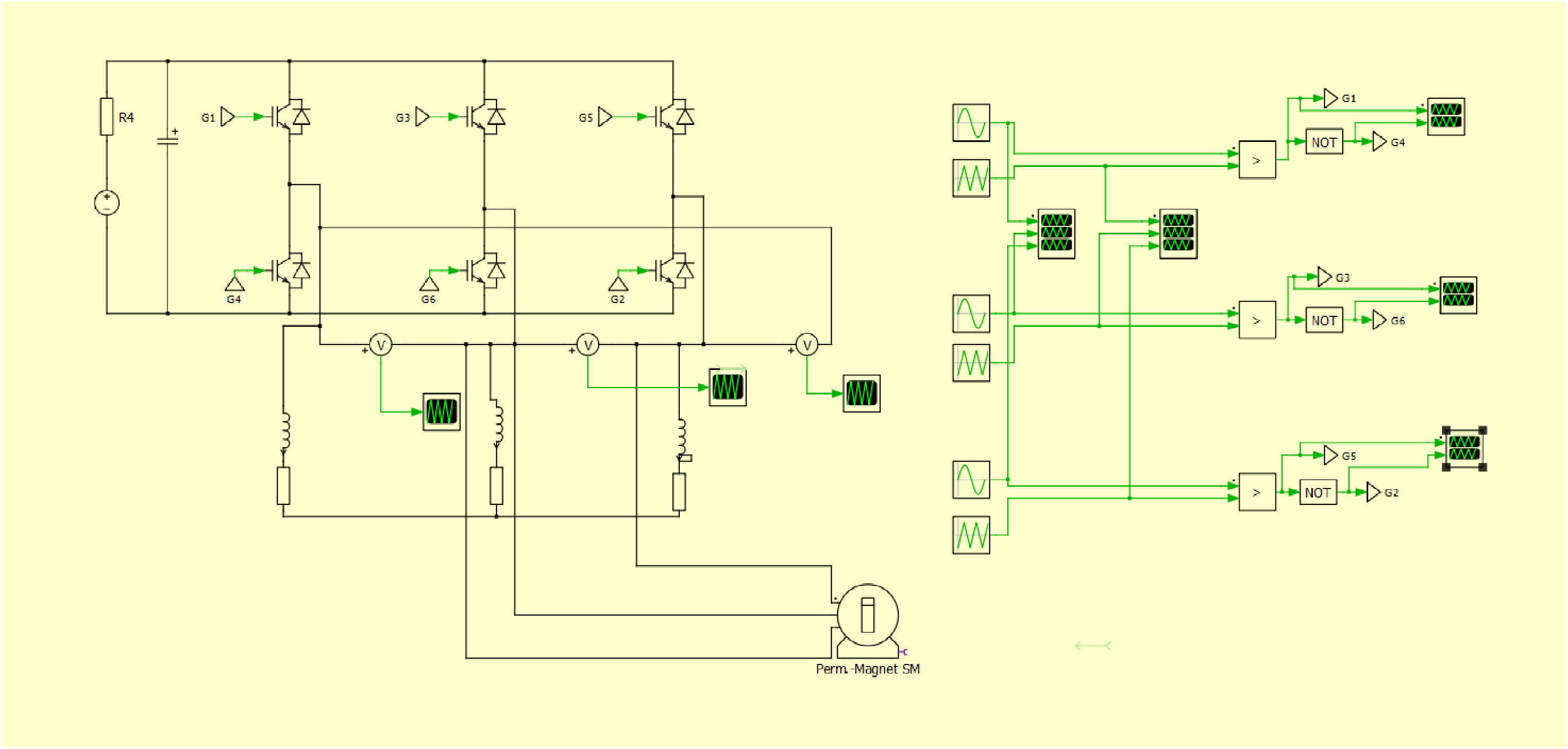
Simulation of three-phase inverter (DC–AC) feeding PMSM. DC: direct current; AC: alternating current.
Figure 2(a) shows the inverter, which is powered by regulated DC input, and it supplies 3.5 kW PMSM motor with 5-level sinusoidal pulse-width modulation topology. The controller in Figure 2(b) performs energy arbitration, capacitor balancing, and duty-cycle switching based on load demand and SOC.
Energy flow behaviour
Figure 6(a) displays the energy profile of all three sources in a 1-h drive, while Figure 7 describes the phase voltage of the inverter, as reported in Obe et al. (2025). Some prominent trends are: (1) solar energy is slowly growing and is variable and can provide up to a quarter of all charge. The major source is (2) battery energy, which is continuously discharged over the entire cycle. As shown in Figure 8, and consistent with the findings in Bhanuchandar and Murthy (2025), the UC charges aggressively from regenerative braking in the first 30 min when there is a high demand period.
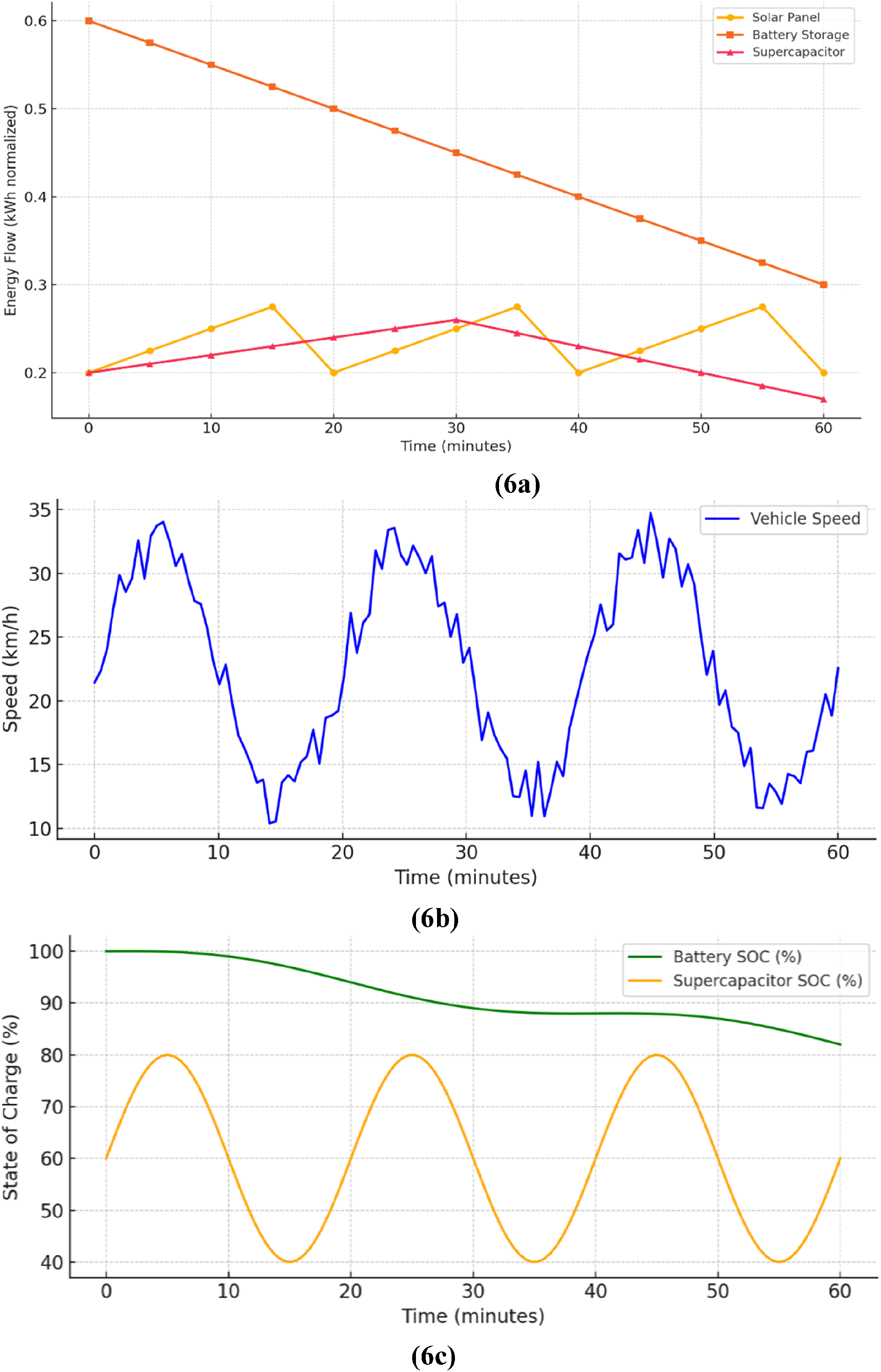
Generated waveform showing: (a) energy flow profile, (b) vehicle speed profile, and (c) state-of-charge variation.
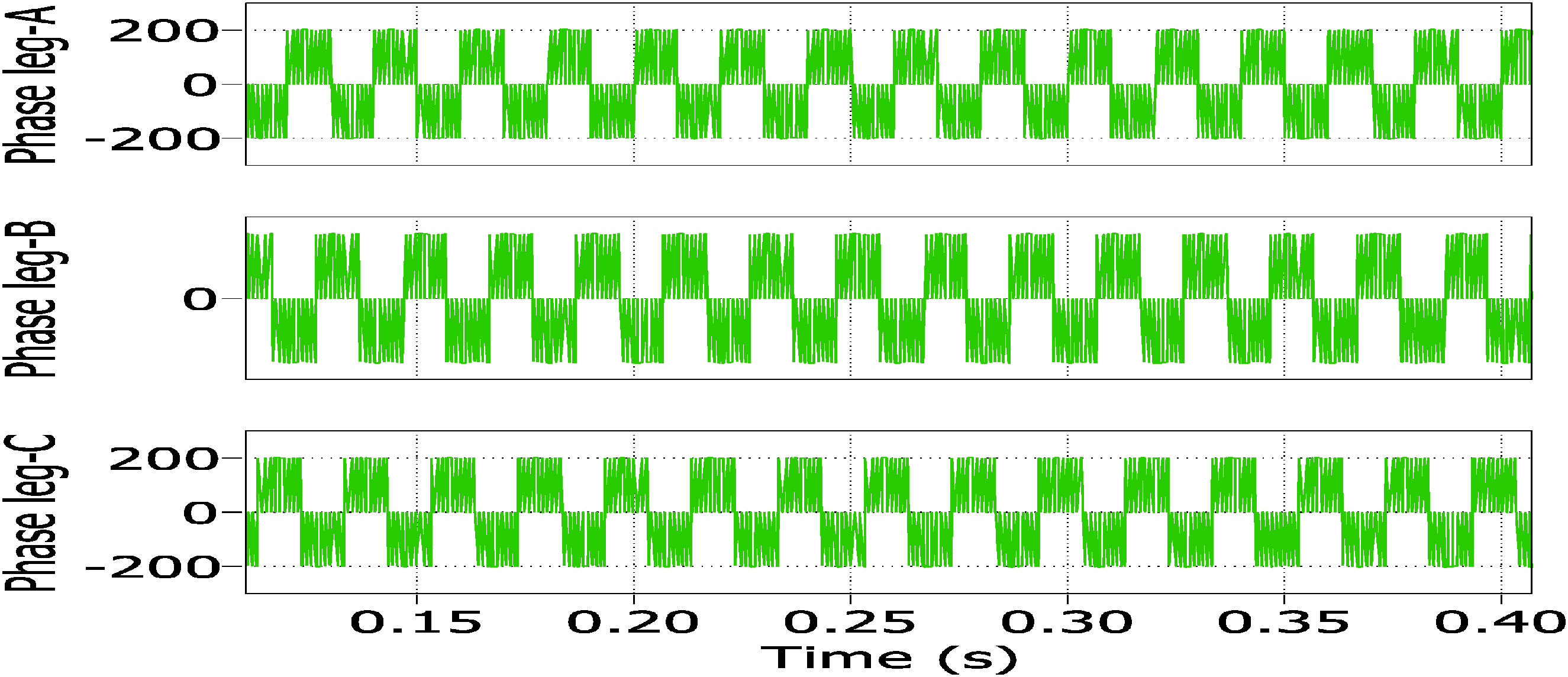
Inverter three-leg phase voltages fed to the PMSM.
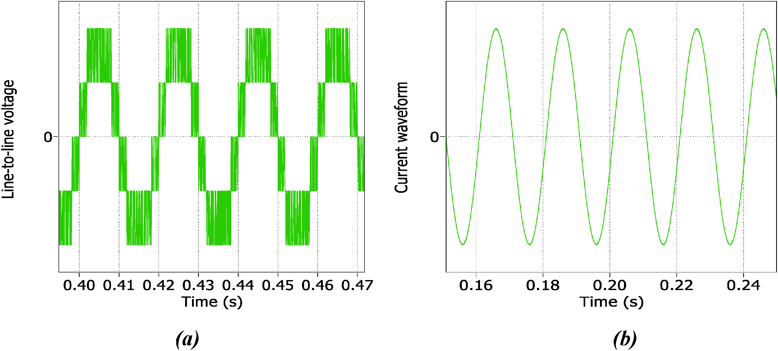
Simulation results showing (a) inverter line-to-line voltage and (b) inverter current waveform, fed to the PMSM.
This dynamic ensures energy savings and reduces load stress on any single source.
Table 3 compares the energy sources by average contribution, efficiency, and cost-effectiveness.
Energy source contributions and characteristics.
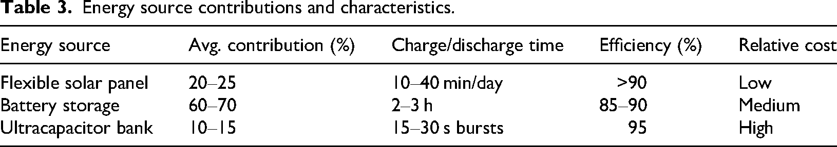
Figure 5 shows the simulation (in piecewise linear electrical circuit simulation model) of how the three-phase inverter functions, demonstrating the transformation of a controlled DC power of the hybrid storage system into the AC waveforms of the PMSM, the heart of the EV propulsion.
An in-depth time-based profile of performance during a 1-h drive cycle is shown in Figure 6(a) to (c). It visually compares the energy flow of all three sources (solar, battery, UC) to the speed of the vehicle and to the SOC of the storage systems showing the dynamic energy arbitrage and the reaction of the system to driving requirements.
The output of the inverter to the PMSM is shown as the clean and synthesized three-leg phase voltages in Figure 7. These waveforms are important as the quality of the waveforms determines the efficiency of the motor operation that lowers the losses and allows the torque to be generated smoothly.
Figure 8 presents a closer examination of the output quality of the inverter, as it shows the line-to-line voltage and the associated current waveform of the motor. These are the necessary results that will be used in checking the stability of the system and the low level of harmonic distortion during loading.
The input capacitor injection boost profile, which is one of the major mechanisms in ensuring stable voltage on the DC bus, is shown in Figure 9. This is more so in the transient conditions, that is, sudden acceleration or regenerative braking energy capture, which ensures a steady power supply.
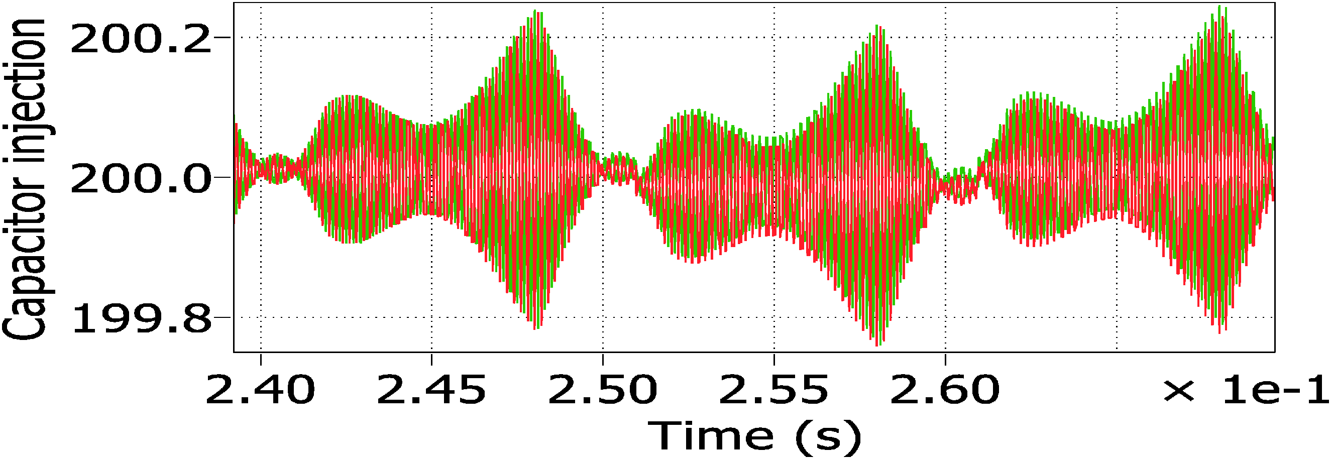
Input capacitor injection boost profile.
Comparison of performance with other literature studies
Comparative analysis shows that the main advancement of this work is not in one specific element, but the overall combination of the established technologies into a system that has been specifically designed to operate in a challenging environment. The findings confirm the hypothesis that this arrangement will be directly used to counteract the primary barriers to EV adoption in Namibia: the absence of charging technology gets resolved through grid-independence, the high rates of energy are reduced with the help of a substantial solar input, and battery life issues are resolved with the hybrid storage approach. Table 4 shows the comparative analysis of the proposed work with other related literature studies.
Comparative analysis with existing literature.
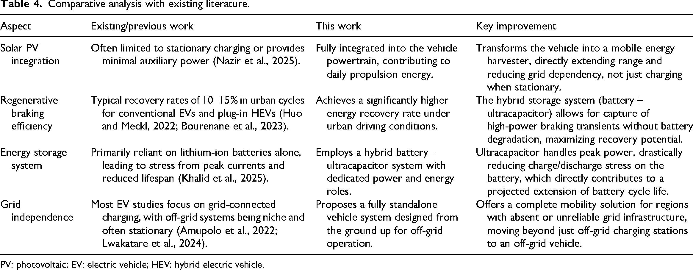
PV: photovoltaic; EV: electric vehicle; HEV: hybrid electric vehicle.
To summarize, the proposed S-HEV architecture, when compared to the current state of the art, offers a quantitatively and qualitatively superior solution to the target use-case, justifying its potential to be used in the catalysed sustainable transport of sun-rich grid-constrained countries such as Namibia. The proposed work is going to be carried out in the future as it is recommended the emphasis will be on the development of high-level multi-level inverters and physical prototyping that will help to translate these encouraging simulation findings into a real-life application.
Discussion and conclusions
Discussion
Due to low inter-annual weather variability, the average monthly and annual energy output of the system can be reliably projected using established meteorological data. Moreover, Namibia has an arid climate with low rainfall, shown in Figure 10 (Mehta et al., 2025), and high solar irradiance, which matches the perfect conditions to operate standalone EVs that are energy-powered by hybrid energy sources. Since the solar availability is stable over seasons, monthly and annual average energy yields can be projected with reasonable reliability based on standardized irradiance data. That is why solar-powered EV systems are very feasible in Namibia and other regions of Southern Africa.
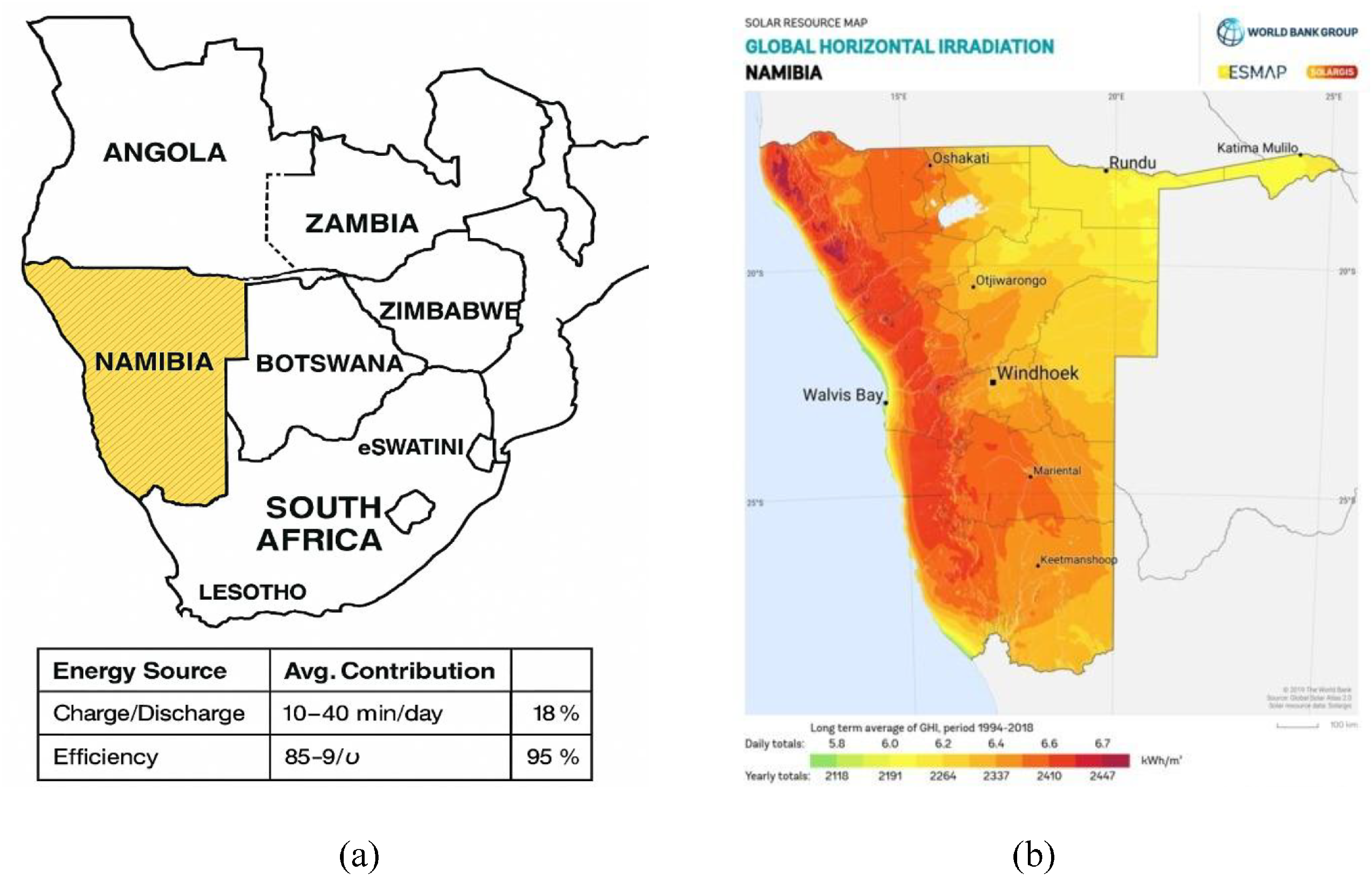
Map showing solar energy availability and climate condition of: (a) Southern African countries reference to Namibia and (b) horizontal irradiation at Namibian urban.
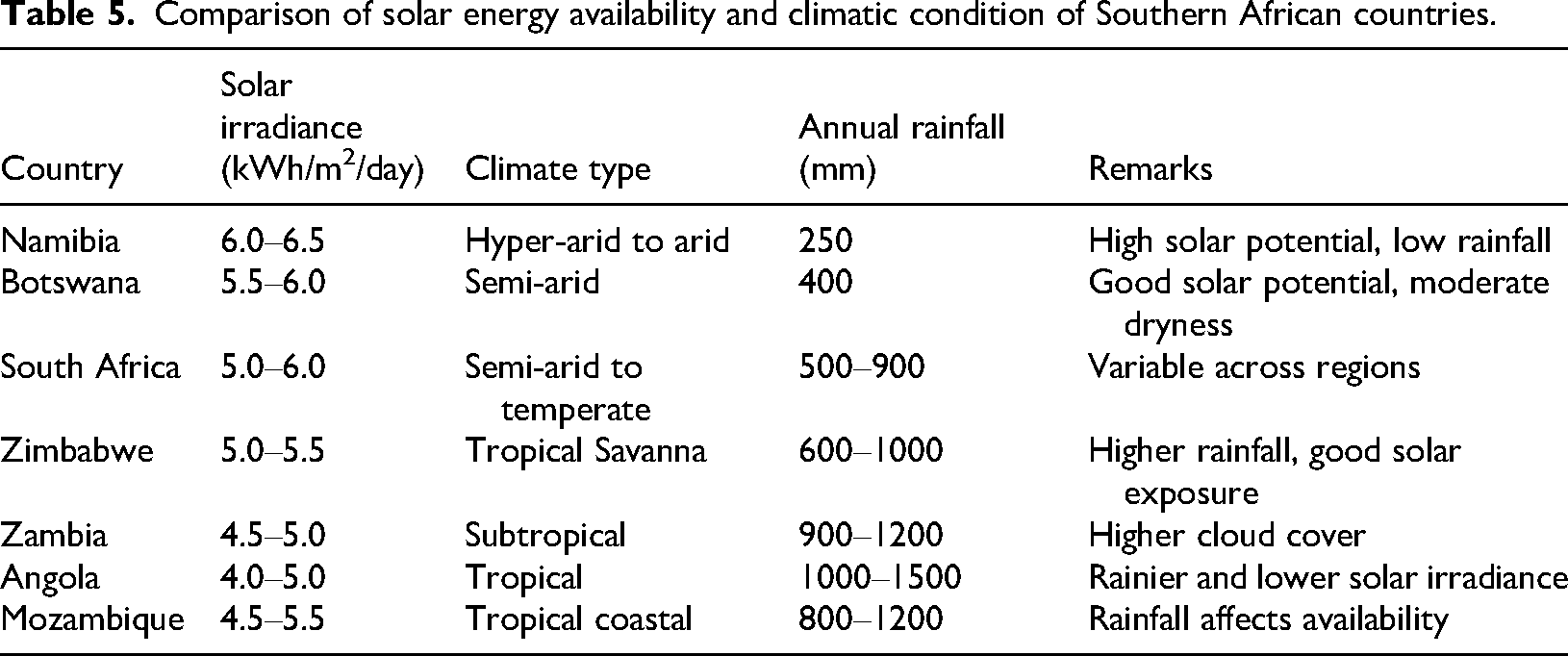
The system proposed includes PV solar energy and regenerative braking, which will charge a dual-energy storage bank, which includes a battery and a UC. Simulation results showed that the PV panel could provide up to 3 kW of power when the irradiance was at its peak and regenerative braking system could provide up to 2.4 kW during the deceleration periods. The UC had better transient response, charging 60% to 82% SOC in 12 min, to supplement a deep-cycle battery that can provide long-term discharge during the drive cycle. Different zones across Southern African countries, shown in Table 5 (Dhar, 2025), present the solar energy availability and climatic conditions.
Comparison of solar energy availability and climatic condition of Southern African countries.
The arid climate of Namibia offers good stability to the system, which helps to show consistent power factor performance even in the transient and load-independent events of the regenerative braking. The conditions also lower the rate of degradation of solar modules and batteries when compared to humid or highly polluted conditions. A DC power change-over controller was incorporated in the system to facilitate the seamless switching of energy sources to ensure the system efficiency.
While hybrid and plug-in EV adoption is advancing in countries like South Africa, Namibia presents a unique opportunity for off-grid, standalone EV systems due to its climate and specific infrastructure needs compared with traditional plug-in as shown in Table 6 (Huo and Meckl, 2022). Based on the geographical adoption of hybrid vehicles, Namibia is poorly utilized even though the country is ideally situated to take advantage of solar-powered mobility. This paper justifies the argument of increasing local adoption by using low-cost, low-maintenance designs.
Baseline comparison between the traditional plug-in HEV and the proposed standalone HEV.
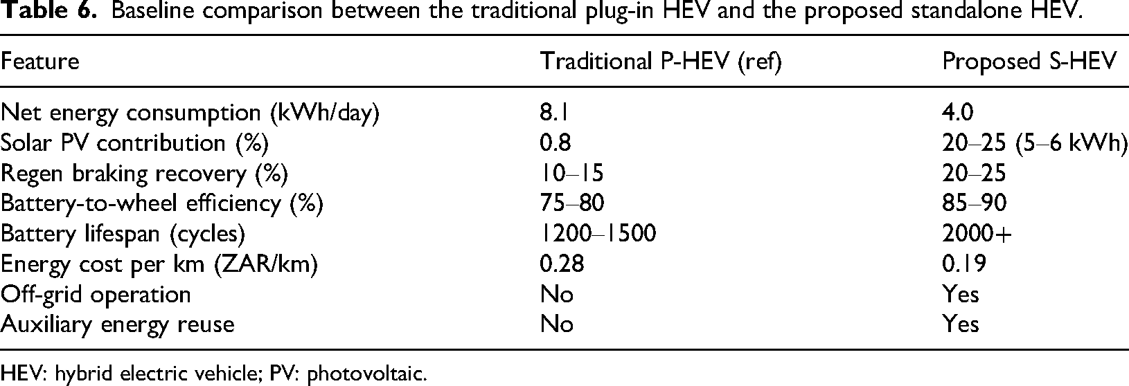
HEV: hybrid electric vehicle; PV: photovoltaic.
The feasibility of the proposed system is also applicable to intercity transport, though performance dynamics are shifted relative to urban cycles. The major difficulty of increased ranges is compensated by the sustained solar PV input. In longer periods of cruising under the high irradiance of Namibia, the 0.9–1.2 kW output of the array is used to directly support the battery which is extremely important in extending the range. But increased speeds decrease the regenerative braking efficiency, as a fewer number of deceleration and larger aerodynamic losses decrease recovery rates below the urban standard of 20–25%. Nevertheless, the UC is crucial in the process of capturing powerful and transient braking events as common in highways driving and safeguarding the battery to enhance effective energy absorption (Alam, 2024). In addition, the sustained power demands are raised by high vehicle loading. The main component is the hybrid energy storage system; the battery will handle the base load of the cruise, when climbing uphill and passing by, the UC will provide an extra burst of power to the powertrain to avoid overloading the main battery and carry it. Although the mix of energy sources will change, making solar energy a more important range-extender and regeneration a less common source, the fundamental architecture of the system remains sound. The combination of the sustained sun harvesting and the battery–UC hybrid makes it reliable to use and thus is a sustainable and viable solution to intercity transport in Namibia as far as grid independence is the most important in the routes.
Environmental impact analysis
The environmental significance of the proposed S-HEV system lies in its potential to drastically reduce greenhouse gas emissions, air pollutants, and dependency on fossil fuels in Namibia's transport sector. The total emission reduction potential can be expressed as:
Namibia's arid environment, characterized by sparse vegetation, low rainfall (250 mm/year), and high insolation provides a natural advantage for solar-based mobility (Lemenkova, 2025). However, dust deposition on panels and high ambient temperatures (often 35 °C) can marginally decrease PV efficiency by 3–5%. To mitigate this, thin-film PV modules with low temperature coefficients and self-cleaning coatings are recommended. Moreover, the regenerative braking sub-system minimizes kinetic energy losses, reducing particulate emissions from brake wear, an often-ignored urban pollutant source. The environmental conditions at Namibia are more stable in their PV yields compared with other neighbouring countries. As an illustration, Botswana and South Africa have moderate cloud cover (5.5 6.0 kWh/m2/day) (Mulaudzi, 2019), whereas Angola and Mozambique have high humidity and precipitation (1000 mm/year) (Lourenco and Woodborne, 2023), which decreases the solar efficiency and corroding of PV and electrical equipment. Therefore, Namibian climatic environment enables greater solar-to-wheel efficiency and greater component lifespan, which leads to a reduced lifecycle carbon footprint.
The suggested system is technically feasible as well as environmentally revolutionary to Namibia and other dry areas. Its complete implementation would decrease the number of emissions associated with transportation, lead to climate resilience, and establish a template on how to achieve eco-friendliness in mobility in similar climatic and infrastructural limitations.
Limitations and challenges
This study has a few limitations and challenges. Technically, it is a highly complex system with several sources of power (PV, battery, UC) each having their own DC–DC converter that makes it more difficult to control and places more chances of failure. High ambient temperatures in Namibia are also extremely susceptible to the solar PV sub-system since it may adversely affect voltage output and the total energy yield (Temaneh-Nyah and Mukwekwe, 2015). In addition, the regenerative braking sub-system, though useful in urban cycles, has reduced energy recovery in constant intensive operations at high speeds intercity where braking is not a common occurrence.
On the economic front, the high upfront price of the major parts such as a lithium-ion battery bank and a high-power UC is a significant obstacle to its mainstream use, particularly in developing countries. Scalability and real-life implementation are also problematic since the results of the simulation should be tested by physical prototyping and the long-term field performance to evaluate the durability of the results, maintenance requirements, and performance under non-ideal weather conditions. Lastly, the effectiveness of the implementation of such a standalone system will be subject to the creation of local technical skills to install, operate, and maintain it, which might be lacking now.
Conclusion
This study has demonstrated the feasibility of an advanced independent EV plan as a transformative solution for sustainable intercity transport in Namibia. The proposed system is a direct solution to the infrastructural problems of the country in that it creates a self-sustainable vehicle architecture that is totally independent of the untrustworthy traditional grid. This is also performed through the smart combination of onboard solar PVs and a regenerative braking system, which harvest energy from the environment and the vehicle's own motion.
The success of this system hinges on its hybrid energy storage strategy which is a combination of high-energy density battery together with high-power density UCs. This collaboration maintains constant and effective power delivery in acceleration and captures the high-power bursts of the regenerative braking with a professional approach, thus reducing stress on the primary battery and extending its lifespan. Moreover, this is supplemented by an auxiliary energy-saving mode that utilizes all surplus energy for auxiliary functions to maximize the overall efficiency.
In essence, this standalone EV model presents a robust, climate-adaptive blueprint for clean mobility. It provides a considerable saving in the cost of operation and environmental impact in addition to enhance in the energy security. In countries with much sunlight such as Namibia, this solution not only eliminates the necessity of large-scale charging infrastructure, but it also paves the way for a resilient, economically advantageous, and sustainable transportation ecosystem.
Recommendations
Building on the current standalone EV platform, the authors strongly recommend transitioning to a three-phase, three-level neutral point clamped inverter topology for the next iteration. This upgrade brings clear advantages: (1) Improved power quality and reduced THD through multi-level voltage synthesis. (2) Lower device stress enhanced thermal management, and greater inverter efficiency. To ensure reliability and scalability, the inverter should be realized on a PCB-based power stage, rather than a breadboard or lumped-hardware setup. A PCB implementation improves component placement precision, minimizes parasitic, allows optimized heat dissipation, and supports manufacturing-ready designs. To implement wider energy plans, additional work needs to be conducted in the future, to produce hydrogen energy-based studies, with referencing to the work of Seepana et al. (Praveenkumar et al., 2022), in the International Journal of Hydrogen Energy.
Footnotes
Funding
The authors disclosed receipt of the following financial support for the research, authorship, and/or publication of this article: This work was supported by the Faculty of Engineering and the Built Environment, University of Johannesburg.
Declaration of conflicting interests
The authors declared no potential conflicts of interest with respect to the research, authorship, and/or publication of this article.