



Abstract
Background
The quality of computed tomography (CT) imaging is important when used to judge the success of joint replacement surgery. Metal artefacts are a known source of error, typically compensated by noise reduction software.
Purpose
To develop a transportable and stable system for the assessment of image quality of bone lesions around orthopedic implants.
Material and Methods
The design and manufacture of a bone-implant-phantom is described, which is based on a calf acetabulum with surrounding pelvic bone structures. Bone lesions of several sizes were created in the acetabulum before implanting the cup of an uncemented hip prosthesis, which was fixed with a stainless-steel bone screw. Plastic strips were placed on a cobalt–chromium stemmed femoral component, simulating typical bone lesions around loosening or infected prostheses, before embedding the stem in material similar to bone and shaped like a femur. The head of the femoral component was then placed in the acetabular cup and CT scans were produced.
Results
It was possible to construct a durable CT hip phantom for quality assurance work. The usability of different materials and the choices made for the phantom are discussed.
Conclusion
It is possible to construct a durable joint implant phantom for quality assurance and scanner hardware and software assessment with limited resources. The phantom was successfully used in the assessment of the hardware and software performance of different CT scanners.
Introduction
Metal implants pose a major and increasing challenge for computed tomography (CT) imaging through the introduction of artefacts. This hinders assessment of bone and soft tissue immediately adjacent to the implant and further away (1). These metallic artefacts are related to beam hardening (2) and all CT vendors have introduced special scan and software algorithms to tackle this problem (3,4). To compare image quality between vendors during a tendering process and to optimize image quality after CT installation, a CT phantom can be extremely useful. It allows image quality to be compared objectively between vendors and software solutions and allows protocol optimization for any given CT scanner by providing a fixed standard.
A number of publications use phantoms that include a metal joint replacement to investigate the quality of CT imaging of soft or hard tissue around metal implants (5–7). However, these studies looked at the overall imaging quality. A specific challenge for radiologists is to assess the status of bone around metal implants, particularly the presence of bone lesions in the periprosthetic bone. Such bone lesions can take a linear (diffuse) or lytic (localized) nature (8), each type likely to give different challenges to the radiologist.
A purpose-built phantom would help to compare different scanners in their ability to handle metal artefacts and allow the visualization of bone lesions around implants. The same phantom could also be used for further optimization of orthopedic implant imaging protocols. Such a phantom should be stable over time and be easily transportable to other sites in order to compare different scanners.
The aim of the present study was therefore to develop a transportable and stable system for the assessment of image quality of bone lesions around orthopedic implants.
Material and Methods
The present study describes the design and production of a CT phantom of a hip with a total hip replacement (THR). In designing this phantom, we followed the guidelines published by the American Association of Physicists in Medicine (AAPM) (9). With respect to beam hardening artefacts, these guidelines acknowledge that such artefacts are usually related to a specific imaging task and therefore do not recommend any particular metallic artifact phantom. Instead, they recommend that clinical colleagues suggest a design for such a phantom. Given the specific clinical topic of the present study, namely metallic artefacts around hip implants, our main design criterion was to imitate a human hip with a THR, surrounded by a number of clinically relevant bone defects, as it appears on CT scans. The materials used, apart from the hip replacement, should thus be similar to human tissue in imaging appearance. The AAPM standard does not give guidelines for the design process. However, the International Society of Magnetic Resonance in Medicine (ISMRM) has established an Ad Hoc Committee on Standards for Quantitative Magnetic Resonance that recently published a report with a set of 15 specific design criteria for MRI phantoms, seven of which are also applicable to a metal artefact phantom for CT imaging (10). These are: (i) publication of the phantom development process; (2) purpose-based shaping of the phantom depending on the replicated body area; (iii) physical (CT) properties and stability of the filling materials well-characterized; (iv) easy handling; (v) costs commensurate with comparable phantoms; (vi) easy and safe to ship; and (vii) durable. The remaining eight criteria are not relevant for CT imaging or are specifically aimed at quantitative examination. A search of the literature was used to select materials that were easy to obtain, easy to handle and had appropriate Hounsfield unit (HU) values.
The femoral component of the implant was surrounded by plaster and clay, modelled in the shape of a human femur. The reason behind using a substitute material for the femur was related to the ability of creating controlled bone defects, which proved relatively straightforward in the acetabulum, but very difficult in the femur.
The acetabular component, on the other hand, was anchored in a natural bone, namely a calf pelvis.
The femoral component chosen was a 210-mm long matte stainless-steel collared implant with an anteroposterior (AP) dimension of 10 mm and a CT attenuation value of >11,000 HU (11,12). Linear periprosthetic bone lesions were created by attaching polystyrene strips (30 mm length × 7 mm width) in thicknesses of 1 mm, 2 mm, and 3 mm. Two strips of each thickness were glued proximally and distally onto the medial, anterior, and posterior aspects of the stem using epoxy adhesive (RS, Corby, UK; approximately 150 HU (13–15)) (Figs. 1 and 2).
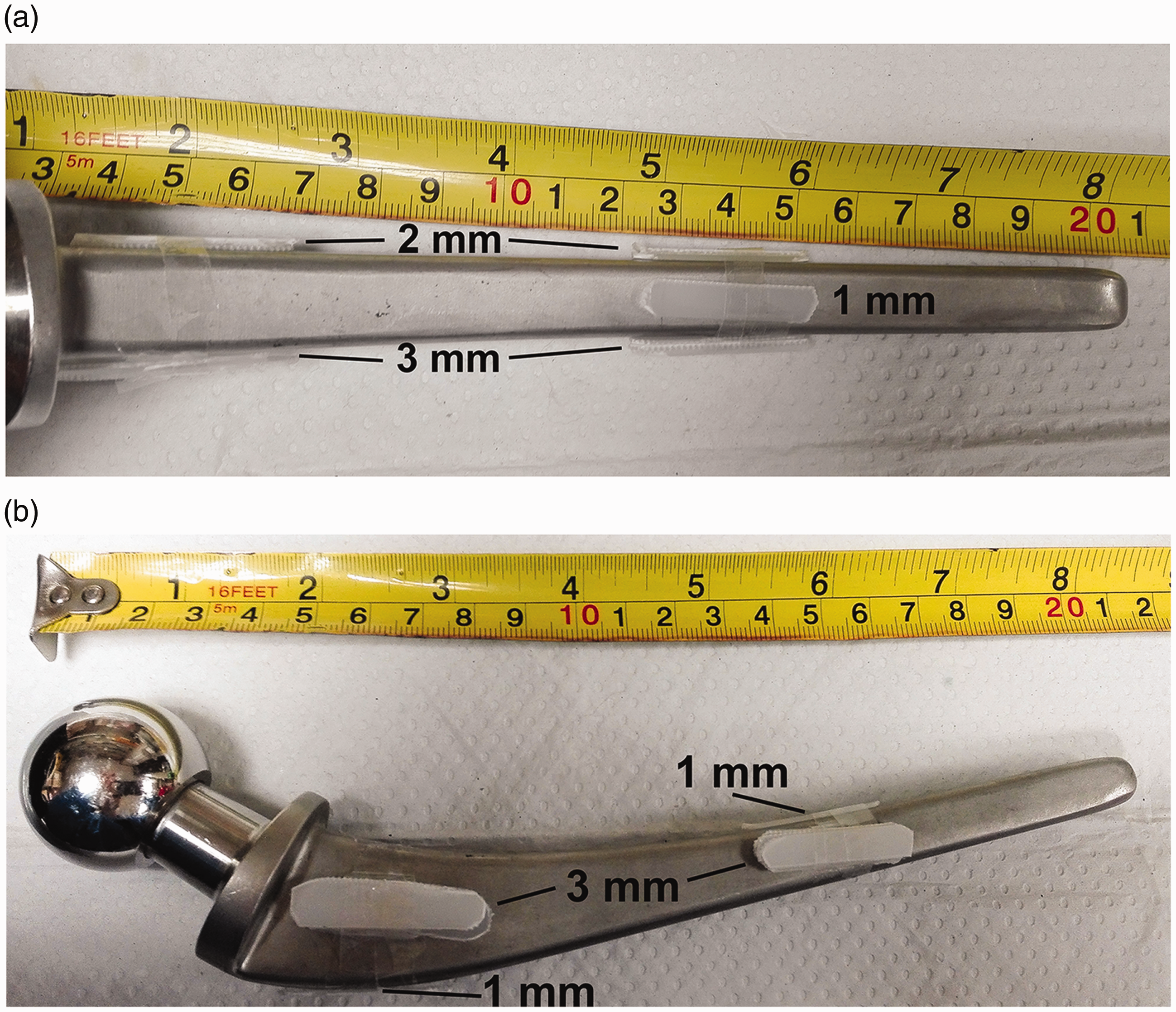
Paraprosthetic spacers to simulate lytic bone lesions when encased by clay.
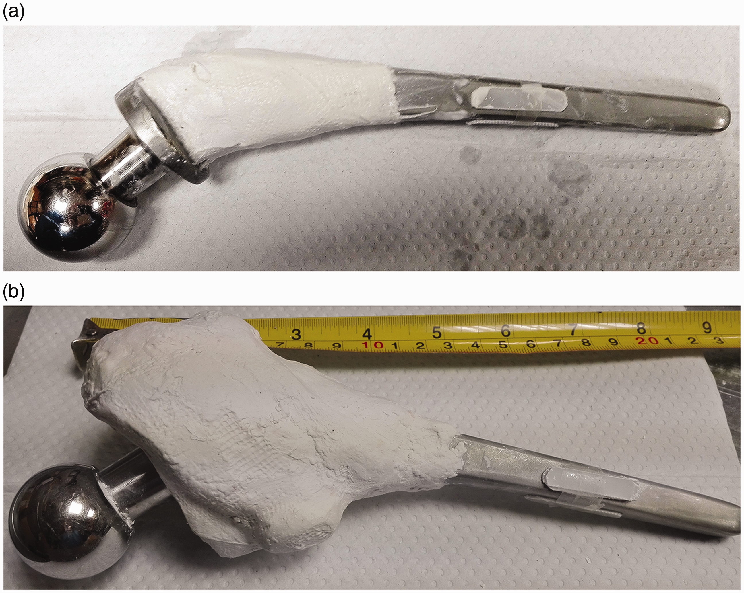
Encasement of the femoral implant with layers of plaster.
The lateral surface remained blank for comparative purposes. Figure 1 shows the configuration of the strips. The 1-mm strips were mounted on the proximal and distal medial surface, the 2-mm strips on the proximal and distal anterior surface, and the 3-mm strips on the proximal and distal posterior surface.
A bone in the shape and with imaging properties of a human femur was made using two different materials. Modelling clay (DAS, Fila SpA, Milan, Italy), having a HU of about 1207 HU, was used to mimic compact bone, and plaster of Paris bandages (Gypsona, BSN Medical Ltd., Hull, UK), with a value of 455 HU, were used to mimic cancellous bone (16).
First, the proximal implant with polystyrene strips was wrapped in the plaster of Paris bandages over a length of approximately 10 cm. The bandages were moistened and wrapped around the implant, taking care not to detach the polystyrene strips from the prosthesis (Fig. 2) The thickness of the plaster layer varied gradually from 1 mm at its distal edge to 50 mm at its proximal edge. The material was then allowed to fully set overnight.
The whole implant, including the plaster of Paris, was then embedded in the modelling clay, simulating the compact bone. This layer was made to be relatively thin proximally (approximately 1 mm), where it covered the “cancellous bone.” Distally, it was made thicker (approximately 5 mm) to mimic mid-shaft compact bone. Distally, the clay extended approximately 2 cm beyond the tip of the implant in order to create a medullary canal with the same diameter as the prosthesis (Fig. 3). Posteriorly, a minor trochanter was mimicked using the same clay.

Clay layer.
The acetabular component of the THR was placed in natural real bone. A calf acetabulum was used for this, as its size is similar to a human acetabulum. After obtaining the acetabulum from a local abattoir, all soft tissue was removed from the bone. To make it durable and prevent spoiling, organic components were removed by simmering the bone with a biological washing detergent (approximately 20 g) in a slow cooker for about one day. Afterwards, the bone was rinsed thoroughly to remove all soft tissue and detergent remnants and was then left to dry for two days at room temperature (17).
Drill bits of 1–5 mm in diameter were used to create 21 lytic bone lesions on the inner surface of the acetabulum (Fig. 4). On the ischial surface, five lesions of 3-mm depth were created using drill bits of 1, 2, 3, 4, and 5 mm. On the iliac surface, eight lesions were created, four pairs of 1 and 2 mm in diameter to a depth of 1, 2, 3, and 4 mm. Eight lesions were also created on the pubic surface, four pairs of 3 and 4 mm in diameter to a depth of 1, 2, 3, and 4 mm (Figs. 4 and 5). All defects were then filled with epoxy adhesive to avoid air locks and simulate the soft tissue in such bone defects.
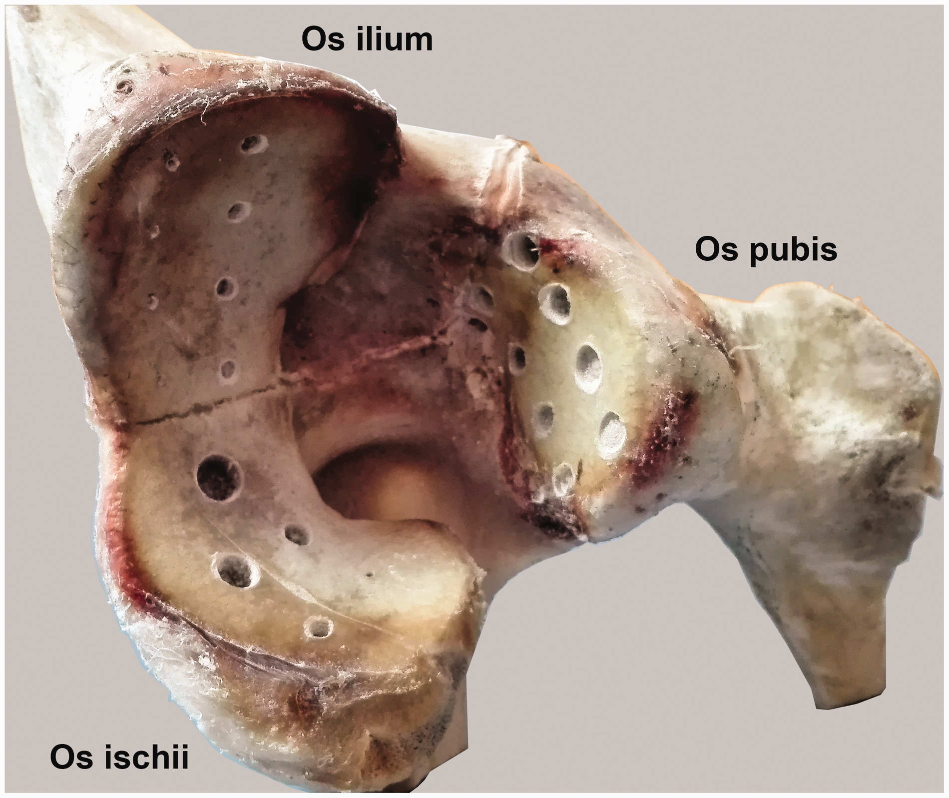
Acetabulum defects.
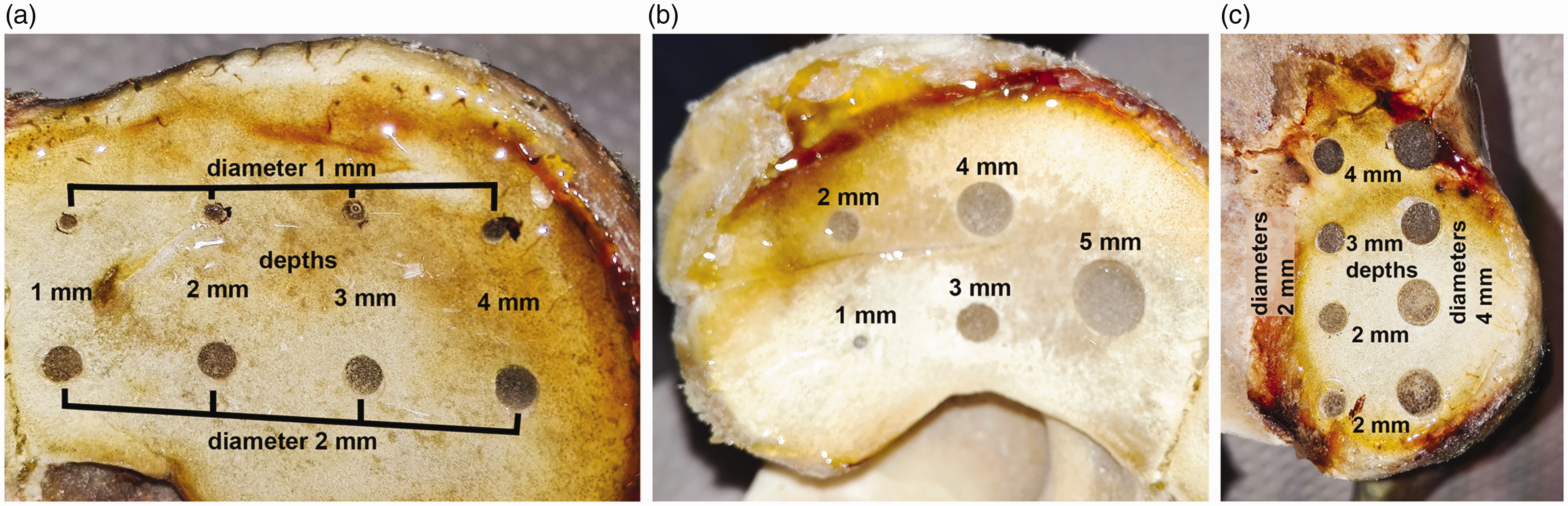
Acetabulum defects in detail: (a) os ilium; (b) os ischium; and (c) os pubis.
The metal backing of an acetabular component of a total hip prosthesis was then placed in the acetabulum and fixed in the pubic bone near the synchondrosis between the pubis and ilium using a stainless-steel cortical screw, similar to its position in a human patient (Fig. 6). Once the metal backing was fixed, the polyethylene liner was pushed in place.
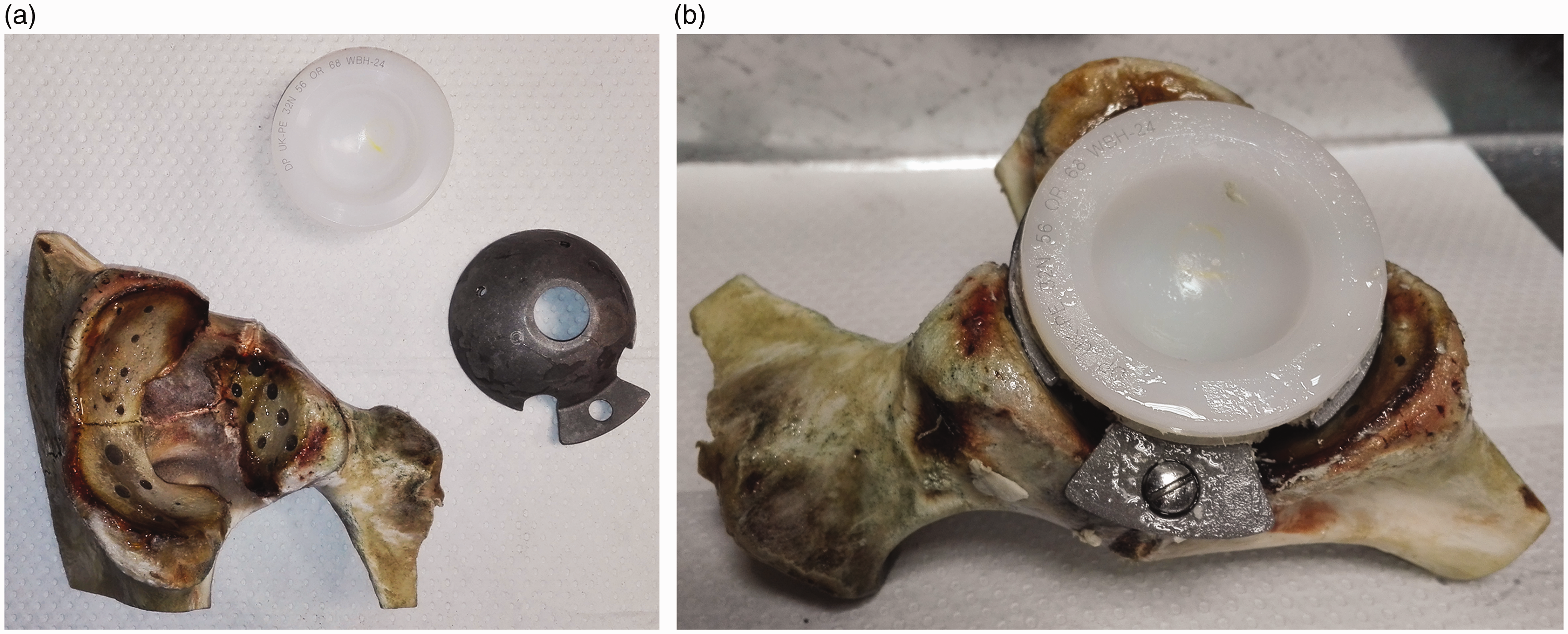
The acetabulum preparation: (a) before assembly and (b) after assembly
The model femur and acetabulum, with the implanted components, were placed in a transparent Perspex box (320 × 150 × 150 mm) made of 10-mm thick transparent polymethylmethacrylate (PMMA) sheets (Figs. 7 and 8). Finally, the model was half-embedded in epoxy resin (approximately 150 HU (13–15)) in order to hold the components in place and to seal the implant phantom surface and protect it against moisture. This radiodensity was comparable to that of the soft tissue which surrounds the hip. Sealing the whole phantom with resin would have resulted in significant weight increase. Instead, when used in practice, the Perspex box would be filled up with tap water, which also has a radiodensity similar to soft tissue (16) and is ubiquitously available and uniform (Fig. 9).
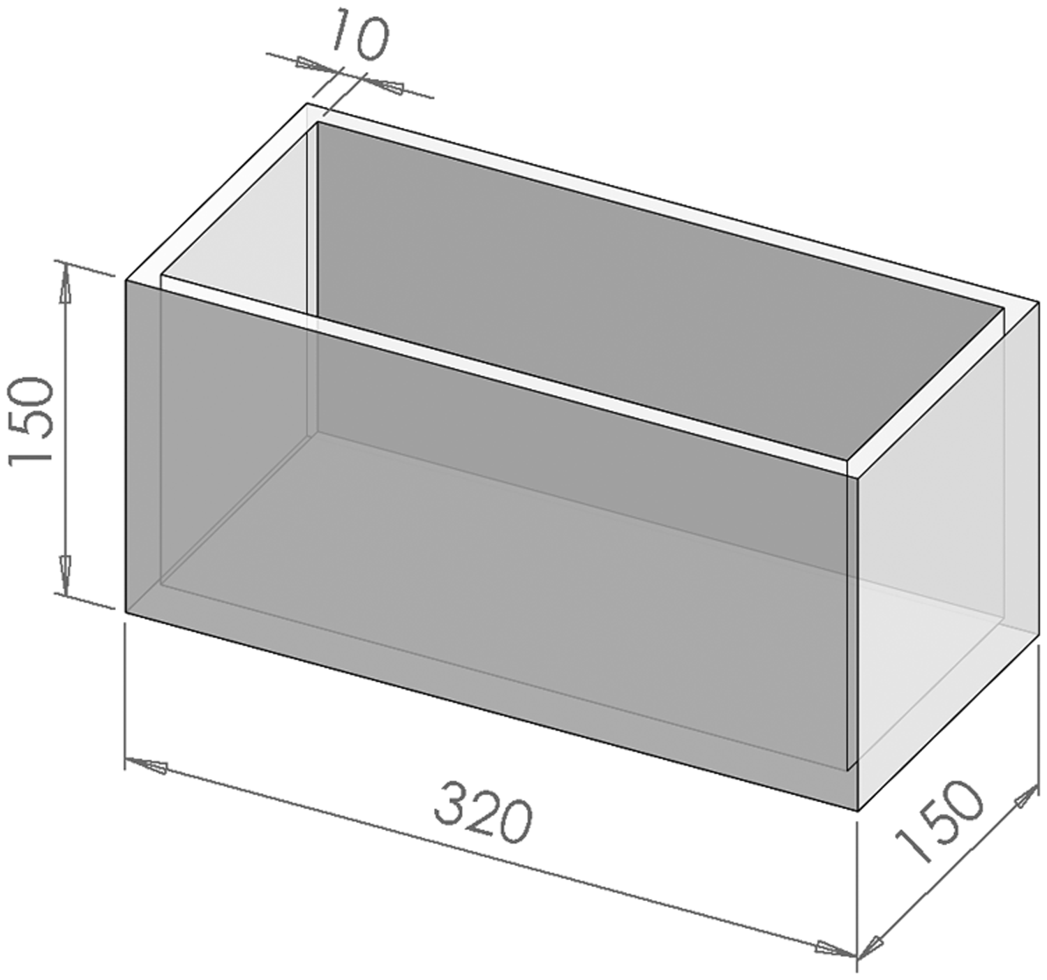
The Perspex box.

The finished phantom views from (a) above and (b, c) the sides.
The phantom was then imaged using a CT scanner (Aquillion 1, Canon, Japan) to assess if it was fit-for-purpose. The Perspex box was completely filled with tap water (approximately 0 HU; Table 1) before placing it in the CT scanner and obtaining images. Three different software algorithms, namely bone, SEMAR (the proprietary artefact reduction algorithm), and a soft tissue algorithm, were used to reconstruct the image. Equal bone window settings (approximately 340 mm in width and 380 mm in length) were used for each reconstruction.
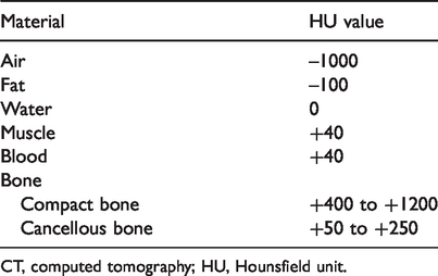
CT, computed tomography; HU, Hounsfield unit.
Results
The above-described phantom build resulted in a mechanically and temporally stable hip implant phantom. The acetabular component was embedded in real bone with multiple periprosthetic defects allowing the assessment of CT scanner performance in a phantom closely simulating a real hip implant.
The femoral component was embedded in a bone substitute with the placement of several bone defects.
The CT phantom is portable and can be used for the purposes outlined in the introduction, that is the assessment of different CT scanners and scan protocols.
Figure 9 provides a CT scan of the hip phantom filled with water on a Canon Aquilion 1. It exemplifies the method of the assessment of periprosthetic bone lesions. The image reconstruction has been performed with three different software algorithms: bone; SEMAR (the proprietary artefact reduction algorithm); and a soft tissue algorithm. The display shown is at equal bone window settings (approximately 340 mm in width and 380 mm in length). A bone lytic defect is visible on the dorsal aspect of the acetabular component. The depiction of this varies across the algorithms and allows for direct comparison. Similarly, the quality of depiction of adjacent bone varies and can be comparatively assessed. SEMAR, an artefact reduction software algorithm, is shown to introduce distortion and blurring in the immediate vicinity of the implant.

CT scans: (a) bone algorithm; (b) SEMAR+; and (c) soft tissue algorithm. The arrow points to an artificial bone defect. SEMAR reduces streak artefact compared to the other algorithms but introduces blurring and distortion.
Discussion
The present study aimed to develop an easy-to-handle, transportable, stable, and low-cost phantom that allows radiologists to assess the quality of CT images of bone lesions around metallic orthopedic implants. By using the phantom, different CT scanners can be assessed, and further optimization of orthopedic implant imaging protocols can be realized. This was achieved by combining an acetabular component of a hip replacement, placed in natural bone, with a femoral component, placed in an artificial bone, and by replicating the anatomic structure. In both types of bone, we produced either localized (lytic) or diffuse (linear) bone lesions, typical of the type commonly seen around hip replacements (11,18). Although both are adjacent to the metal replacement, the two types of defects may pose different challenges to CT scanners and their image reconstruction algorithms.
Our CT phantom complies with the relevant AAPM guideline (9) and with the relevant design criteria proposed by the Standards committee of the ISMRM (10). Some earlier phantom designs used fresh human cadaveric bone and therefore do not comply with the criteria of durability, simple handling, and shipping as proposed by the ISMRM (5,19). Other earlier designs, such as that by Pauwels et al. (6), used PMMA and different types of metal, thus complying with the proposed ISMRM criteria. However, that phantom did not address a specific clinical problem in the manner suggested by the AAPM guideline. The proposed method of phantom construction—based on an implant, a preserved bone, or material to make a bone-equivalent and a method to create clinically relevant bone defects—should be universally applicable and similar phantoms can be constructed for other parts of the skeleton. For instance, based on the experiences from the present study, a simplified knee phantom has been constructed by some of the authors (20).
In order to ensure that the phantom challenges CT scanner capabilities, the metal implant was chosen to have a high attenuation. With a higher implant density and thickness, the X-ray beam is attenuated more, and more marked beam hardening, photon starvation, and streak artifacts occur (17). A stainless-steel metal alloy hip prosthesis was chosen for this purpose. A material such as titanium, which is also used for hip prosthesis, would produce fewer artifacts than, for example, cobalt–chromium or stainless-steel alloys (6).
Ideally, the authors would have used human bone in combination with a hip prosthesis. However, human tissue is subject to the Human Tissue Act and not normally available for such purposes. The integration of the femoral implant into the femur and creation of femoral bone lesions also would not have been straightforward. Nevertheless, because natural bone should be the best substitute for human bone, we chose to use an animal acetabulum for part of our phantom. The animal acetabulum should have the similar size and anatomic structure to the human acetabulum. On these criteria, a calf acetabulum was deemed appropriate because its dimensions are virtually identical to those of an adult human acetabulum (5,21).
For the femoral component, use of a calf femur was considered. However, bone fixation as described in the result section leads to brittleness making implant fixation more difficult. This could be achieved with bone cement but, in addition, it would have been very difficult to place defined defects into the femoral cavity. Therefore, the authors decided to artificially recreate the femur using material with a similar attenuation to real bone. Cancellous bone has typically attenuation values of 50–250 HU, whereas the compact bone has values of 400–1200 HU (Table 1). The research before the building of the phantom showed that the materials are suitable for this application. Only the modelling clay is slightly to dense. However, both materials made it relatively easy to replicate the bone geometry.
Ideally the material which replaced human soft tissue, such as muscle and fat, should have an attenuation between −100 and +40 HU (Table 1). The epoxy adhesive in the bone lesions of the acetabulum’s inside surface and the epoxy resin in the Perspex box have a value of around 150 HU (Table 1). The value slightly exceeds the ideal value range. However, the epoxy resin surrounded the bones and fixed them centrally in the watertight Perspex box.
Using the resin in this way kept the complete structure relatively light and allowed the box to be filled with tap water (approximately 0 HU; Table 1) at sites of testing to ensure simulated soft tissue around the complete bone. Tap water has a similar attenuation to human soft tissue. Water can be added to the phantom just before using it and drained after every use. Water is cheap, ubiquitous, and uniform, and has also been used in other studies (5). Encasing the entire phantom in epoxy resin would make it much heavier. Covering the phantom only partly will also allow placing additional structures next to the phantom for further research, such as the wires for fixation of the greater trochanter after a trochanteric osteotomy or cerclage wires. Such additional structures may give additional artefacts and increase the difficulty of imaging. The user can use this to perform tests under more challenging conditions.
Care must be taken when casting the resin, encasing the implant bone combination, because the resin contracts when curing. If the resin is cast too thick, the contraction causes cracks in the resin. Besides being unsightly, this may lead to air pockets when filling with water or water retention after draining the water. Cracks can be prevented by successive application of thinner layers, allowing each layer to cure completely before applying the next layer.
Some studies use phantoms that are further abstracted from the clinical scenario. However, these phantoms do not allow the assessment of anatomical detail, especially next to an orthopedic implant (4).
In conclusion, building a durable yet flexible CT phantom for the validation of CT scanner performance in the assessment of orthopedic implants is described in detail and discussed as a simple, easy-to-use method to validate CT image quality.
Footnotes
Declaration of conflicting interests
The author(s) declared no potential conflicts of interest with respect to the research, authorship, and/or publication of this article.
Funding
The author(s) disclosed receipt of the following financial support for the research, authorship, and/or publication of this article: The materials were obtained by the Robert Jones and Agnes Hunt Orthopaedic Hospital, Oswestry, UK.
