




Abstract
This article described a backstepping flux observer and a backstepping control strategy applied to the wind energy conversion system based on synchronous generator. The proposed control technique is developed for both converters: the stator-side converter and the grid-side converter. The stator flux is recovered by the backstepping flux observer, and simultaneously, we introduce stator resistance variations to test the robustness of nonlinear backstepping control strategy. Then, MATLAB simulation works show high performances in terms of tracking, stability, and robustness against parameter variations.
Keywords
Introduction
Wind energy conversion systems (WECSs) based on the permanent magnet synchronous generator (PMSG) have been increasingly used. This is due to several factors the most important one is the absence of the gearbox between the PMSG and the turbine, it minimizes the cost and the maintenance frequency.
Besides, compared to induction generators, the PMSG is characterized by the high power to inertia ratio and the ease of control (Mahersi et al., 2013b). Several control strategies have been studied to control the synchronous generator (Dominguez and Imbaquingo, 2015; Ladide et al., 2014; Mahersi et al., 2013a). The vector flux–oriented control (FOC) strategy is widely used to control the PMSG (Akin and Bhardwaj, 2013; Cimpoeru, 2010). However, the traditional proportional–integral (PI) controllers cannot perfectly solve the problem of coupling between the rotor speed and the stator currents. The FOC technique cannot offer stability and high precision on speed control. Therefore, diverse nonlinear control techniques have been developed such as sliding mode control (SMC; Mahersi and Khedher, 2014; Zhang et al., 2012) and the backstepping control (BC; Chen et al., 2015; Qiao et al., 2012). In this article, we concentrated on nonlinear BC technique. It has been studied and developed to control the induction machines (Khemiri et al., 2012a; Trabelsi et al., 2010b) as well as the PMSG (Lagrioui and Mahmoudi, 2011; Mahersi and Khedher, 2016).
The backstepping design is based on a recursive nonlinear controller by considering some of the state variables as “virtual controls.” The overall nonlinear system is divided into small linear subsystems; each subsystem outputs represent the control inputs for the next subsystem. All control stages are based on the Lyapunov theory (Morawiec, 2013). The BC is commonly used due to its efficiency and insensitivity to parameters variations, and it reduces the hardware complexity.
The speed and current are considered available for feedback but the stator flux is inaccessible for measurements. Thus, it is necessary to integrate a flux observer on the design control in order to make the stator flux known for feedback on one hand and to reduce the cost on the other hand. In this trend, diverse research works are devoted to the concept of an adaptive flux observer taking into account parameter variations, such as Kalman filtering technique (Akin et al., 2004), sliding mode flux observer (Bullo et al., 2011), and backstepping flux observer (BFO; Nademi et al., 2008). The latest is one of the most efficient flux observers in the literature (Trabelsi et al., 2010a). In fact, the design of the observer is based on the backstepping algorithm, so that the prediction errors of the flux components are considered as the state variables of the system in order to adjust the tracking errors between the prediction errors and its reference trajectories. The BFO take into account the parameter variations, that is why the online estimation of the resistance is required to guarantee the stability of the whole system with the application of the Lyapunov theory.
In this article, our study will focus on the synthesis of the adaptive BFO inserted into nonlinear BC strategy design of the WECS based on the PMSG. The article is organized as follows: section “Modeling of the WECS” recalls the modeling of WECS based on the PMSG. Sections “SSC control” and “GSC control” deal with the development of the BC strategy for the stator-side converter (SSC) and the grid-side converter (GSC), respectively. Then, the formulation of the BFO with the estimation of the stator resistance is presented. Finally, the adaptive nonlinear approach is tested with dynamic simulation using MATLAB/Simulink; the results are illustrated and discussed in section “Simulation results.”
Modeling of the WECS
The studied system is composed of three-bladed wind turbine, a PMSG, two power converters, a DC-link capacitor, and a grid filter. The stator of the generator is connected to grid through a full-scale voltage source converter. Two control strategies are applied to the SSC and the GSC. Figure 1 presents the design of the WECS based on the PMSG.
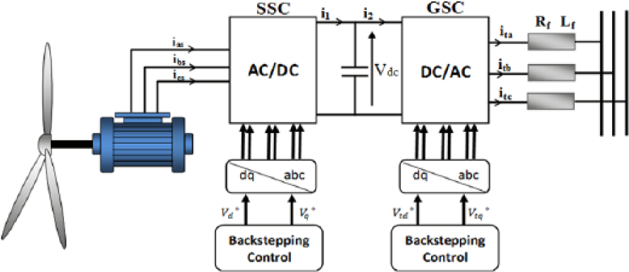
Structure of the wind energy conversion system based on the PMSG.
Turbine model
The wind turbine transforms the wind energy to a mechanical energy. The equation describing the mechanical energy conversion system is given as

where the mechanical torque

So that, the power extracted from the wind turbine is written as

PMSG model
Under assumptions commonly used in AC machine modeling, electrical equations of the PMSG expressed in a (d, q) reference frame are given as (Meghni et al., 2016)

The reference frame is linked to the rotor flux vector, so the stator flux components are expressed as

The electromagnetic torque is linked to the current by expression (6)

The stator active and reactive powers can be written as follows

SSC control
The basic idea of BC is to decompose the nonlinear control design problem into various design steps. Each step provides references for the next design step (Hamidaa et al., 2012). For the PMSG control design, the BC can be achieved by two successive steps.
State model of the system
Taking into account equations (4) and (5), the state model of the system can be presented as
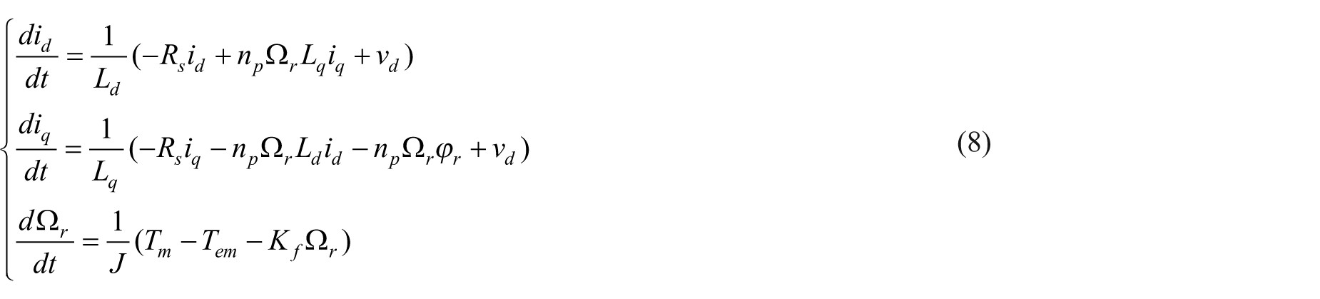
Assuming that vector control conditions are verified (Rahman et al., 2003), the direct current component is maintained at zero. This results in the electromagnetic torque being directly proportional to the quadrature current component; furthermore, the stator flux linkage
In that way, the resultant PMSG state model can be expressed as (Roy et al., 2015)

BC design
Step 1. Computation of the reference stator current
The speed tracking error can be defined by

The speed error dynamic can be presented as

To reduce the speed tracking error to zero, the current components are identified as the virtual control elements. Using the stability theory, the Lyapunov function is defined as

The derivative of

where
The Lyapunov function becomes

Step 2. Computation of the reference stator voltage
Let us consider the current tracking errors are expressed as follows

Using equations (14) and (15), equation (11) becomes

From equations (8) and (14), the derivative of the current tracking errors can be expressed as

To determine the stator voltage references, a new Lyapunov function based on the speed tracking error and current component errors is defined as

By differentiating the second Lyapunov function, one easily obtains

By substituting equations (16) and (17) in equation (19), the derivative can be expressed as follows

where

The derivative of the Lyapunov function is considered definite negative if

Thus, one can easily obtain the following d–q voltage references

where k1 and k2 are the positive parameters selected to stabilize the system.
The bloc scheme of the BC strategy applied to the SSC is presented in Figure 2.
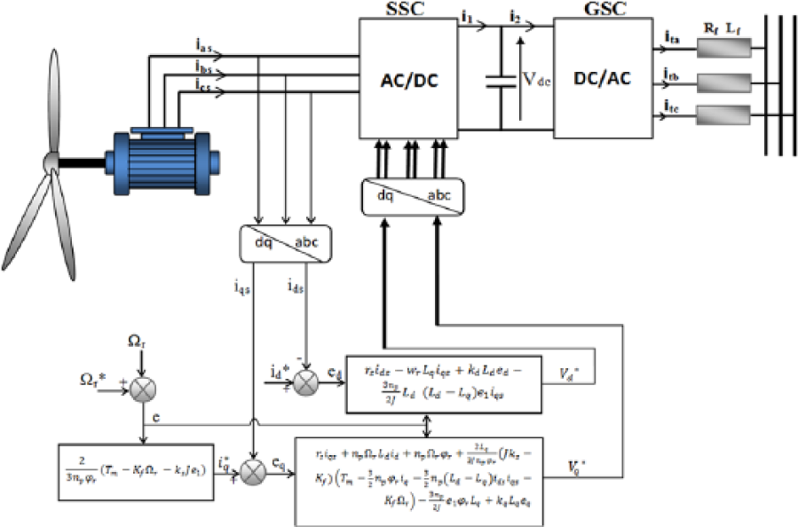
Bloc scheme of the backstepping control strategy applied to the SSC.
GSC control
The GSC is connected to the grid by an intermediary line characterized by a resistance Rf and an inductance Lf . It keeps the DC-bus voltage constant and controls the power transmitted to the grid.
State model description
The grid-side equations are expressed in the (d, q) reference frame as

where ωg is the grid pulsation.
The active and the reactive powers exchanged to the grid are linked to the current components by the following expressions

In this session, we adopt the conditions of the vector control strategy; thus, the direct axis of the reference frame is oriented to the quadrature grid voltage vector, we obtain
Consequently, the state model defined in equation (24) becomes

and power expressions (25) are reduced to

One can easily conclude that active power transmitted to the grid dynamics depend on the quadrature current component control, while the reactive power is related directly to the direct current component.
BC design
The grid current errors are defined as

The derivative of the above equations gives

In order to generate the references of line voltages, we have to define the Lyapunov function related to the grid current errors. It can be written as

Referring to equations (26) and (29), the derivative of equation (30) is expressed as

To insure the condition that the Lyapunov function is definite negative

such as
After satisfying conditions mentioned above, the derivative of the Lyapunov function becomes

DC-bus voltage control
The main role of the DC bus is to allow the energy transmission between two converters of different frequencies. The DC-bus voltage can be expressed as follows

where
The DC voltage is controlled via a PI controller in order to maintain the voltage constant. This controller generates the reference current


Bloc diagram of DC-bus voltage control.
Neglecting losses in the resistance of the filter and in converters, we can write the expression of the power delivered to the grid as follows

While, Q*, the reference of the reactive power is set to zero in order to guarantee the system operation with power factor equal to 1.
The current component references

The bloc diagram of the BC strategy applied to the GSC is showed in Figure 4.
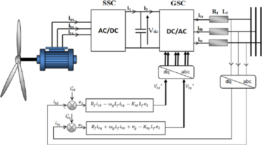
Bloc scheme of the backstepping control strategy applied to the GSC.
Adaptive BFO
A BFO is proposed to calculate the stator flux components. Only the stator flux and the stator resistance are replaced by their values created by the BFO. Using equation (5), one can conclude that stator flux components depend directly on stator current components. Hence, the flux observation requires the observation of the stator current components.
The BFO can be formulated as (Belabbes et al., 2006)

where

where e1 and e2 are the stator current observer errors. The prediction error dynamic is given by the following equation

BFO design
The observer is based on the backstepping technique, thus it is accomplished by two steps.
Step 1
We define the integral of the currents prediction errors as follows (Galeazzi et al., 2013)

Then, the tracking errors of the prediction errors are expressed as follows

The observer’s dynamics are based on the exponential convergence, so that the expressions of the references of the prediction errors are written as

Step 2
Substituting equation (43) in equation (42), we obtain

Thus, the control inputs are expressed by the following equation

and

Stator resistance estimation
The BFO takes into account the variations of the stator resistance, so that, the latter has been estimated via the Lyapunov function written as (Khedher et al., 2007)

where q is a constant positive gain
The derivative of the Lyapunov function is given by

To satisfy the Lyapunov condition and make the function definite negative, we have to adjust the expression of the stator resistance adaptation as follows

The stator resistance variations are presented in Figure 5.
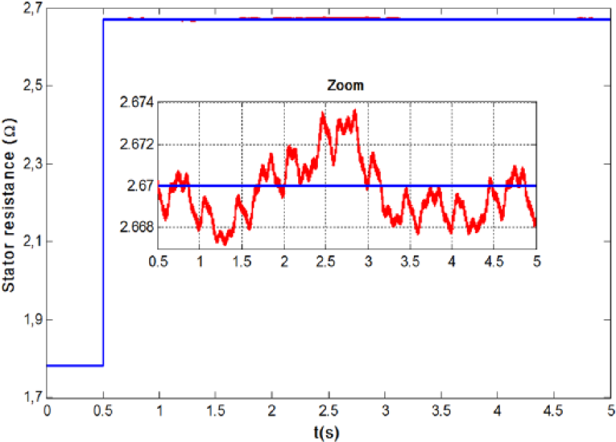
Stator resistance variations: reference and estimated values.
Figure 6 shows the whole structure of the control system with BFO.
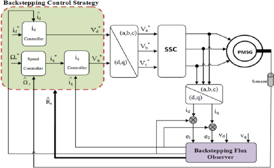
Configuration of the proposed SSC control strategy with BFO.
Simulation results
The overall WECS design is implemented on the MATLAB–Simulink interface, and it is simulated to investigate performances offered by the BC strategy applied to the SSC and the GSC with an adaptive BFO. Parameters of the turbine and the PMSG are presented in Appendix 1.
All simulation studies are achieved with the same DC-bus voltage equal to 790 V and the same wind speed modeling as the following sinusoidal function

The wind profile represented in Figure 7 shows two velocity peaks; the first peak registered at 0.9 s and the second one at 5.1 s.
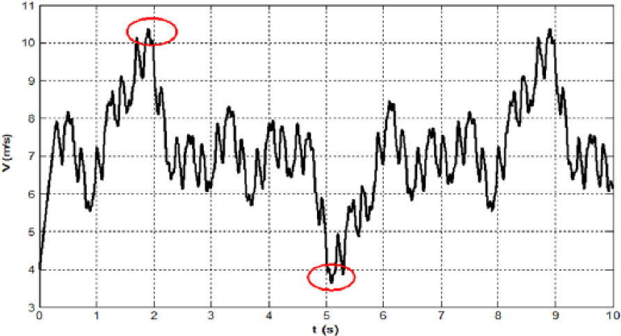
Wind speed profile.
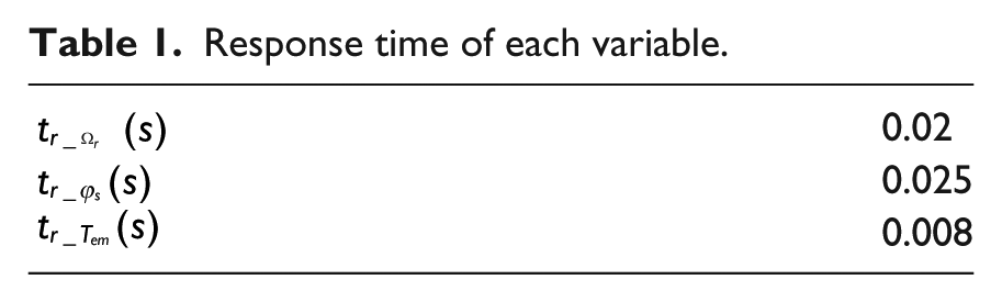
First, we focus on the response time of the rotor speed, the stator flux, and the torque as presented in Table 1. One can easily conclude that the speed, torque, and flux have quick responses when both converters are controlled by the BC strategy.
Response time of each variable.
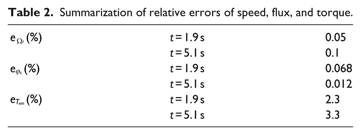
Second, we investigate, in Table 2, relative errors of state variables under BC. In fact, errors of the speed, flux, and torque are defined at two different times of peak (at t = 1.9 s and t = 5.1 s).
Summarization of relative errors of speed, flux, and torque.
Generally, the error of a variable “

In our study, “
From Table 2, we can conclude that all errors of the speed and the flux are small. So that, Tables 1 and 2 show high performances in precision, tracking, and robustness of the WECS based on the PMSG under BC strategy.
Subsequently, we present responses of the rotational speed, the electromagnetic torque, the stator flux, the DC-bus voltage, the active power, and the current transmitted to the grid in Figure 8. As shown in these figures, all estimated variables follow its references trajectories perfectly even with several fluctuations of the wind allowing small tracking errors.
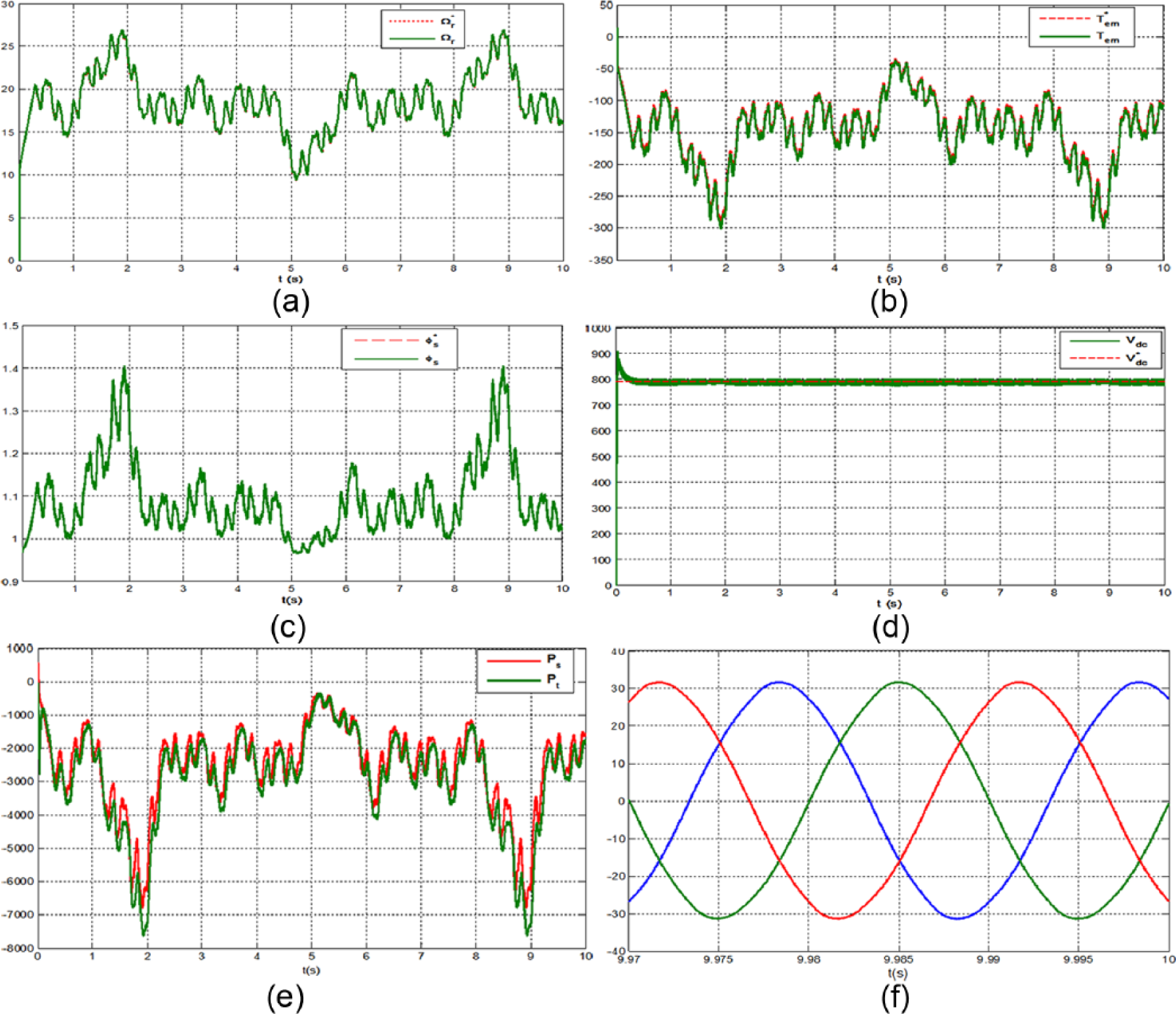
Simulation results under BC strategy: (a) rotational speed (rad/s), (b) electromagnetic torque (N m), (c) stator flux (Wb), (d) DC-bus voltage (V), (e) active power (W), and (f) grid current (A).
The mechanical speed, illustrated in Figure 8(a), records a low value when the wind speed is decreased at t = 5.1 s which confirms the correspondence between the rotational speed and the wind speed.
In addition, one can note that the electromagnetic torque is affected by the fluctuations of the wind speed as shown in Figure 8(b). Figure 8(d) shows the DC-bus voltage profile, and it converges rapidly to its reference value at 0.02 s. It can be seen that the BC strategy offers good results when applied in the GSC.
Also, the stator active power and the active power delivered to the grid are affected by the variations of the wind speed as investigated in Figure 8(e). Figure 8(f) shows a sinusoidal profile of grid currents and having constant frequency equal to 50 Hz.
Finally, in order to exhibit good results obtained with the BFO, we have studied the WECS response under the proposed control strategy with stator resistance variations. We have introduced a sudden increase in the stator resistance at t = 0.5 s. The corresponding simulation results are presented in Figure 9.

Simulation results of the BC strategy under stator resistance variations: (a) zoom of the speed, (b) zoom of the torque, and (c) zoom of the flux.
Hence, as shown in Figure 9(a), few variations can be seen in the rotational speed profile when the resistance is increased at t = 0.5 s. The zoom of the electromagnetic torque presented in Figure 9(b) proves the robustness of the control strategy, in fact within the resistance increase, the torque has overshoots to the normal profile but it returns after about 1 s and follows its normal trajectory. In addition, the stator flux is insensitive to the resistance variations as seen in Figure 9(c); the flux follows its reference trajectory with a few oscillations not affecting the system control. As a review, the BC strategy with the BFO is characterized by its robustness against stator resistance variations proving the stability of overall system.
Conclusion
An adaptive BFO for BC strategy applied to the WECS based on the PMSG is developed. The BC technique is designed to control both the converters: the SSC and the GSC. Due to the unavailability of the stator flux for measurement, an adaptive flux observer based on backstepping algorithm is investigated. An adaptive mechanism of the stator resistance has been introduced to prove the robustness of the system controlled via BC strategy. Despite the consecutive fluctuations of the wind speed, all cases of control present high dynamic performances in tracking and precision. Hence, results show perfect tracking responses and robust characteristics against stator resistance variations.
Footnotes
Appendix 1
Declaration of conflicting interests
The author(s) declared no potential conflicts of interest with respect to the research, authorship, and/or publication of this article.
Funding
The author(s) received no financial support for the research, authorship, and/or publication of this article.