



Abstract
This article presents theoretical calculations of using a plasma actuator in a wind turbine for increasing its regulating ability. Calculations were done taking into account the pressure difference caused by an ozone layer. A series of calculations were carried out based on the QuickField software with the use of calculations of elastic deformations for determination of the influence on the resultant lift force. Distribution of the dielectric strength was calculated that is required for estimation of the ionization area. Vector diagrams were presented which show the influence of the plasma actuator at different sides of a wind turbine blade on the resultant lift force. The equation describing the influence of the plasma actuator was derived. Investigations carried out in this article have shown that the maximum regulating effect is about 25%. It should be noted that the position of the plasma actuator on the blade also influences the value of the lift force. Therefore, regulating properties of wind turbines are improved. Theoretical calculations were validated experimentally at the National Renewable Energy Laboratory in Denver. Note that the main advantages of the plasma actuator as the part of a wind turbine are simplicity and the possibility of increasing regulating properties of a wind turbine.
Introduction
Alternative energy is one of the most dynamically developing branches of modern energy. Research and development of new technical tools and solutions for improving the regulating capacity (or capacity factor) of wind turbines is also growing rapidly. These are increasingly being included in new wind turbine installation requirements. It is important to note that the need to increase the regulating capacity of wind turbines determines the operational reliability. Figure 1 displays the two different ways that the lift curve can be adjusted. It depicts a graph showing the behavior of the lift coefficient (CL) with respect to angle of attack (α) changing the aerodynamic properties of the wind turbine blades. Figure 2 shows a plot of the lift force with respect to the wind turbine blade angle of attack, comparing the improved range control capability versus the standard mode regime.
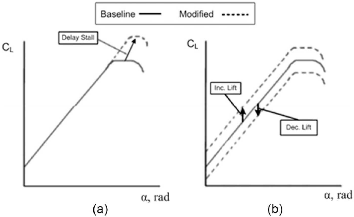
Adjustments in lift curve due to flow control techniques: (a) Delay Stall devices and (b) Inc. Lift/Dec. Lift devices (Ketchman and Velkoff, 1968).
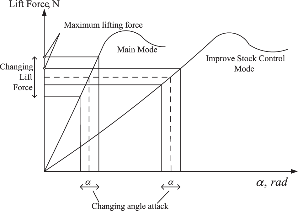
Lift versus the angle of attack in the context of increased regulating capacity adjustment.
Research to improve the maintenance of the generator speed has been conducted by numerous authors (Jafari et al., 2014; Morren et al., 2006; Taghizadeh et al., 2014; Valsera-Naranjo, 2011). Eduardo Valsera-Naranjo and others consider a method to deal with grid frequency deviation. The method is based on reserving a percentage of power extracted from the wind turbine. The results show that the proposed pitch control can contribute to power stabilization (Valsera-Naranjo, 2011). Morren et al. (2006) consider the influence of distributed generation units on primary frequency control.
A recent development in the field of aerodynamic flow control is that of plasma actuators (Figure 3) which were first developed in the late 1960s by Ketchman and Velkoff (1968). However, only in recent years (mid 1990s until today) did plasma actuators undergo considerable research and development; thus, the first commercial applications are yet to come into realization (Pechlivanoglou, 2012).
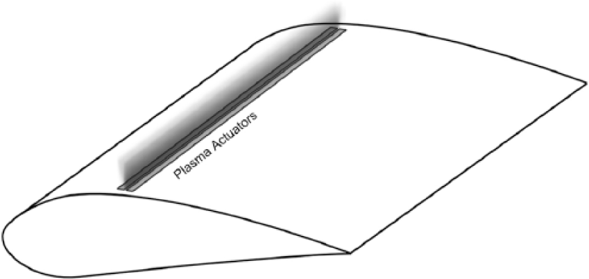
Wing with plasma actuator.
Due to the limited implementations of the plasma actuator technology in current products and aerodynamic applications, the available information regarding the reliability and operation characteristics of such applications is virtually non-existent.
This article presents theoretical investigations of the plasma actuator. Section “The concept of plasma actuator” of this article describes the principle of operation and investigations of other researchers who obtained experimental results. Section “Simulation and implementation results” includes the mathematical formulation of the influence of the plasma actuator on the lift force and calculations of electric field strength distribution. In section “Conclusions,” the main conclusions and results of investigations are given.
The concept of plasma actuator
A known issue with the plasma actuator configurations is their sensitivity toward Reynolds number (Re) variations and more specifically their reduction in effectiveness with the increase in the free-stream velocity (Van Dam et al., 2008). Eisele et al. (2011) investigated the operation of plasma actuators on wind turbine airfoils at a wide range of Reynolds numbers and found that the effect of all the investigated plasma actuators vanished at Re > 105. The energy conversion efficiency is also another operational parameter which highly depends on the actuators design and undergoes further investigation. Currently, plasma actuator systems have low efficiency and very high thermal losses. Additionally, the effects of environmental conditions need to be further investigated to examine the possibility of further implementation of plasma actuators on wind turbine blades. More specifically, the plasma actuators would be required to operate effectively and reliably under rain, hail, and ice and tolerate dust and contamination and lightning strikes (Pechlivanoglou, 2012).
Plasma actuators can be used in various types of flow control and flow modification applications depending on their type and positioning. The use of plasma actuators in an intermittent mode allows for the excitation of Tollmien–Schlichting instabilities in laminar flows, and thus triggering transition and achievement of stall delay. Other types of actuators, such as the plasma wall jet actuators, are able to create plasma sheets, vertical or at angle with the wall surface, thus achieving effects similar to vortex generators (Corke et al., 2008; Van Dam et al., 2008). Shear flows can also be manipulated by plasma actuators via triggering Kelvin–Helmholtz instabilities (QuickField, n.d.).
The application of these principles in airfoil flow control is currently under extensive investigation. The results for low and medium Reynolds numbers are positive, while the effectiveness of these solutions at high Reynolds numbers is significantly reduced (Van Dam et al., 2008). With respect to wind turbine applications, plasma actuators are under extensive research (Eisele et al., 2011; Rodríguez et al., 2007) and their applications in this field seem to be promising. Apart from the apparent application in substitution of the popular passive vortex generator solution, there is also the possibility to utilize them as means of drag and vorticity reduction at the blade root region. Recent experiments by Pechlivanoglou and Eisele have shown that the existence of plasma actuators could reduce the drag due to the Karman vortex shedding behind a bluff body and at the same time generate lift. Such a bluff body is the cylindric root of wind turbines blades where the application of plasma actuators is currently investigated.
The DC surface corona discharge actuator consists of two wire electrodes mounted flush on the surface of a dielectric profile (Figure 4(a)). When a high DC voltage (>10 kV) is applied, a corona is formed around the smaller diameter wire (usually the anode) and an electric wind is created tangential to the surface between the two electrodes. The electric wind is capable of modifying the boundary-layer airflow profile. Figure 4(b) displays a visualization of low-velocity airflow along a flat plate. If the actuator is off, the smoke remains horizontal. When the actuator is active, flow above the anode is entrained toward the surface from the outer layer, causing the smoke to be drawn to the surface and then accelerated in the discharge region. The advantage of this device is that it requires a simple power supply; however, the design is limited to use in an electric wind velocity of only a few meters per second (Da Rosa, 2012).

(a) Schematic view of drive DC corona discharge and (b) 2D visualization of controlled airflow along the flat plate (Cooney, 2009).
Simulation and implementation results
Electric field strength produced by a flat plate is determined by the following equation (QuickField, n.d.)

The finite element method (FEM) in QuickField was used to analyze the electrostatic field (Ketchman and Velkoff, 1968). Electrostatic problems are described by the Poisson equation for the scalar electric potential U. The equation is as follows (QuickField, n.d.)

Electric field strength is given by the following expression

The electric charge of an ozone particle in the electrostatic field is given by

In the plasma, an ozone particle is surrounded by other charged particles. Owing to Coulomb (electrostatic) attraction, plasma particles prevail nearby the considered particle that has an opposite charge related to the charge q. They weaken (or screen) the particle field in the plasma. As is known, a potential ϕ of a charge q field is decreasing with the distance r in the plasma faster than in a vacuum

A Debye screening length D is determined by

Equation (6) allows for the utilization of the calculation of lift force under plasma actuator operations and its influence on components under examination.
Figure 5 shows a cross section of the airfoil. When airfoil flows act as an aerodynamic force, they can be divided into two components: the lifting force and resistance. The lifting force acts on the airfoil perpendicular to the direction of flow leakage rate (υr). The resistance force coincides with the direction of the velocity vector free stream flow. Figure 6 depicts the lift (dFL) and drag (dFD) forces, as well as the plasma actuator action according to its location on the blade surface. The angle between the direction of flow and speed free stream is α.
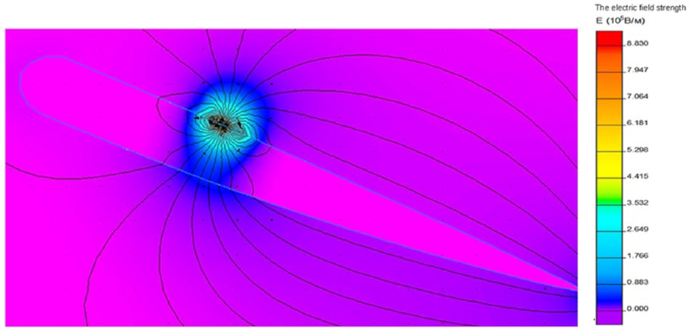
The result of the calculation of the distribution of the electric field on the surface of the blade under the influence of the DC surface corona discharge.
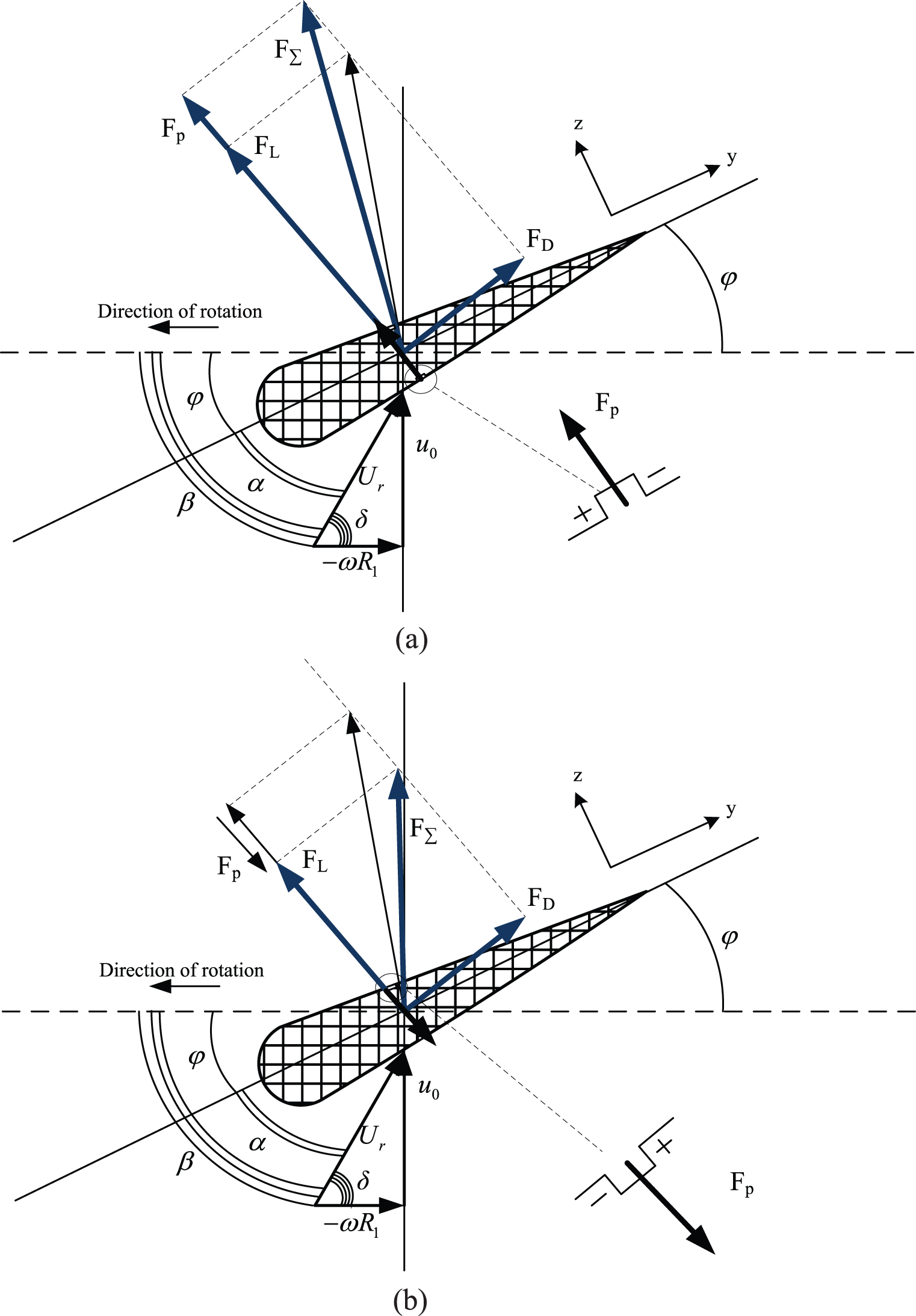
Vector diagram of forces and airflow rate on airfoil cross section: (a) with increasing lift force and (b) with limited lift force.
Lift (dFL) and drag (dFD) forces are determined by Rodríguez et al. (2007)

The resultant relative velocity defined through its direction δ and its modulus Ur, which is determined by the rotational speed ω through
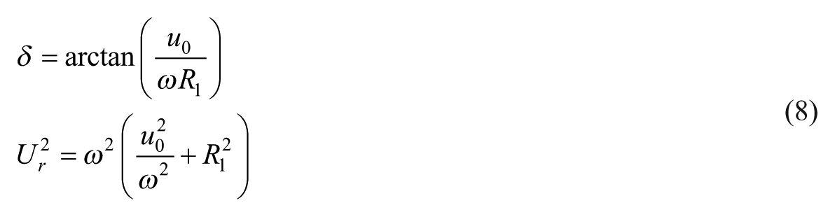
Calculating the component p makes it possible to determine the amount of lift. The wind speed given by the boundary condition is constant. For calculations of mechanical tension, wind speed is formulated numerically through pressure, described as (Ketchman and Velkoff, 1968; Oertel, 2004)

The pressure difference caused by gas ionization depends on temperature and electric field strength

The pressure difference may be also given by

Consider (8) and derive the equation for u1

An additional load acting on a wind turbine blade is expressed by

According to the Wiedemann–Franz–Lorenz law, which makes a relation between the thermal conductivity, the electrical conductivity and the temperature for molecules of an ionized ozone, the following expression is obtained (Aldo V. Yes. Rose, 2010)

Using the similarity method for problems of aerodynamics and mechanical strength, mechanical field calculations are carried out, where pressure increment produced by ionized area of a wind turbine blade is taken as initial data (Cooney, 2009).
The software package QuickField (n.d.) was used again; this time to model the influence of the DC surface corona discharge on wind turbine blades.
Figure 5 depicts the calculation results of the electrostatic field, on which a visible area of a high concentration of lines of force on the surface is causing a corona discharge. Ionized gas creates extra pressure and, in turn, affects the lifting force.
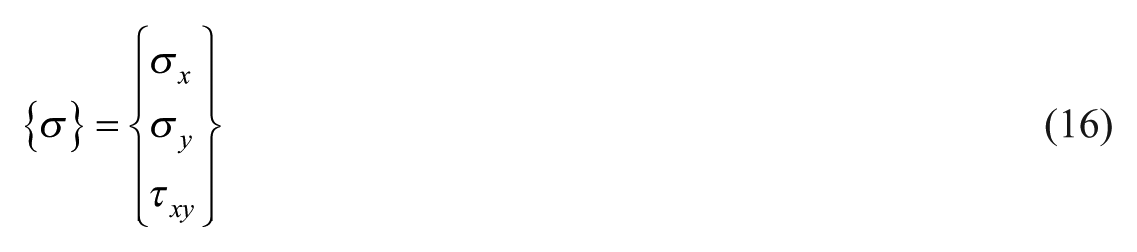
Figure 6 shows the calculations of mechanical deformations performed by usage QuickField. This software allows solving problems of the theory of elasticity in terms of plane stresses, plane deformations, and axially symmetrical stress distribution with isotropic and orthotropic materials. In two-dimensional formulation, the displacement field is assumed to be completely defined by the two components of the displacement vector δ at each point (QuickField, n.d.)

The corresponding stress is defined as
The equation for volume force density is given by
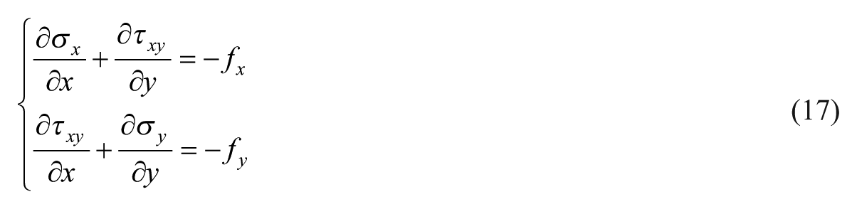
Calculations of the fy component enable determination of the lift force.
Wind speed, being the constant value, is given by a boundary condition. In terms of stresses, wind speed is formed through the pressure parameter according to the following equation

Calculations of the mechanical deformations were conducted in QuickField. Figure 7 shows the representation of the flux field calculation result of mechanical deformations that affect the wind turbine blade in contact with wind flow.
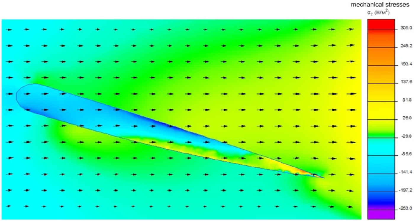
The result of the calculation of the mechanical stress distribution.
Figure 8 shows the calculation results based on the blade lift versus angle of attack, which illustrates the effect of increasing the regulating capacity of the wind turbine blade lifting force using a DC surface corona discharge on its surface.
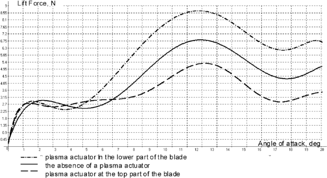
Comparative characteristics of the wind turbine blade lift versus the angle of attack.
The significant advantages of the plasma actuators in the field of mechanical structure (e.g. small size and robust construction) lead to easy and effortless integration on wind turbine blade structures. The integration process involves a simple adhesion step where the plasma actuators, in the form of stripes, are glued on the blade surface. The only elements that need to be properly integrated are the actuator power cables. The overall power requirement of such systems is very low (Berg et al., 2007; Cooney, 2009).
Conclusion
Investigations described in this article show significant influence by the plasma actuator on the lift force. The regulating effect on the airfoil increases the effective range of operation by up to 25%. Calculations of dielectric strength distribution for estimation of the ionization area and determination of the pressure difference on the basis of the ionized gas temperature are also presented in this article.
A mathematical model of DC surface corona discharge was used based on experimental studies conducted in the United States. On the basis of this mathematical model, it is shown that this DC surface corona discharge, in comparison to a conventional pitch-regulated wind turbine, will increase the available regulating capacity to change the angle of attack, which ensures reliable operation of the wind turbine in high wind load conditions. With the wind turbine in power-limited mode, the presence of a plasma actuator would minimize the need for low blade angle of attacks. Power corona discharge technology will provide access to the rated power of the wind turbine in less time, as shown in the simulation results.
Theoretical investigations presented in this article are supported by experimental results.
Footnotes
Appendix 1
Declaration of conflicting interests
The author(s) declared no potential conflicts of interest with respect to the research, authorship, and/or publication of this article.
Funding
The reported study was supported by RFBR, research project No. 16-38-00147 mol_a.