
Abstract
In this article, a comprehensive model is developed to study the performance of a hybrid wind–diesel energy storage system. Energy storage system exchanges both real and reactive power with the wind–diesel system to improve both frequency and voltage. For obtaining pre-disturbance steady-state scenario of the system, a modified load flow algorithm is proposed which calculates induction machine slip and other initial conditions, in addition to the results obtained with conventional load flow. A compact model is developed by integrating network model, energy storage system and machine equations along with the associated control systems. For frequency estimation concept, centre of inertia is utilised. Energy storage system is modelled as a controllable current source. Complete modelling is carried out in MATLAB/Simulink environment. Simulations are carried out for load disturbance as well as wind perturbations to demonstrate the efficacy of the proposed scheme.
Keywords
Introduction
Isolated power systems have experienced a fast development in the areas where grid connectivity is not feasible. These systems are installed at places with abundant renewable energy sources, like wind, and are often integrated with the existing diesel unit to increase the system reliability (Das et al., 1999; Kusakana and Herman, 2014). A good application of such standalone system is that generated power can be supplied to near load centres which eliminates the requirement of long transmission lines (Kim et al., 2013). The control of power quality in such systems is however a challenging task; any disturbance like variation in generation and loading condition can cause havoc on the system performance (frequency and voltage) because of low system inertia (Rehman et al., 2012). An important requirement of standalone system is to maintain constant frequency and voltage. Frequency and voltage variation depends on the difference between demand and supply of real and reactive power, respectively (Das et al., 1999; Kaseem and Abdelaziz, 2014). Frequency control of an isolated wind–diesel system using energy storage under load disturbance has been reported, but voltage control has not been touched, also effect of wind disturbances has not been considered (Kouba Nour et al., 2016). In the study of Jeffries et al. (1996), dynamic response of a wind–diesel system has been reported but without any energy storage system (ESS).
The mismatch in active power can be taken care by fast-acting energy storage devices and their power conditioning system. Different energy storage devices are available in the market like pumped storage hydroelectric systems, battery ESS, redox flow batteries, superconducting magnetic energy storage (SMES) systems, super capacitors and flywheel ESS (Mitani et al., 1988; Sebastian, 2017). This article deals with the modelling and simulation aspects of a hybrid wind–diesel system with energy storage for power quality improvement. ESS is modelled as a controllable current source which injects both active and reactive components of current into the system enabling both frequency and voltage control. Network model is developed using MATLAB function available in the Simulink library and is integrate with the machine and ESS model along with their control systems to form a compact model.
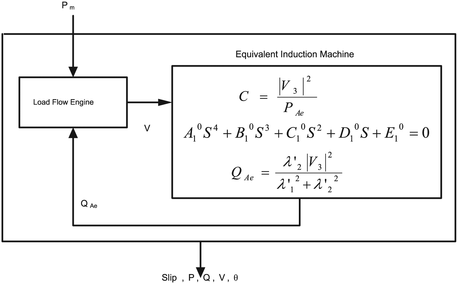
System considered comprises induction machine, so conventional load flow algorithm is not applicable. A modified load flow algorithm is developed which calculates the initial value of slip for induction machine along with the conventional load flow results. System considered comprises two synchronous generators, so to estimate the system frequency concept, centre of inertia (COI) is used (Ortega Milano, 2016).
Wind energy conversion system (WECS) is modelled using a squirrel cage induction generator where eight induction machines are represented by a single equivalent machine (Lone and Mufti, 2004). Two synchronous generators of equal rating with automatic voltage regulators (AVR) and speed governor are used. Loads are represented by admittances, and capacitor bank used for reactive power compensation of induction machine are modelled by equivalent admittances. Block diagram of the system is shown in Figure 1. ESS is installed at bus number 3 where induction machines are connected. Modelling of wind–diesel system, network modelling, energy storage, modified load flow are discussed, and simulation results obtained are shown in figures.
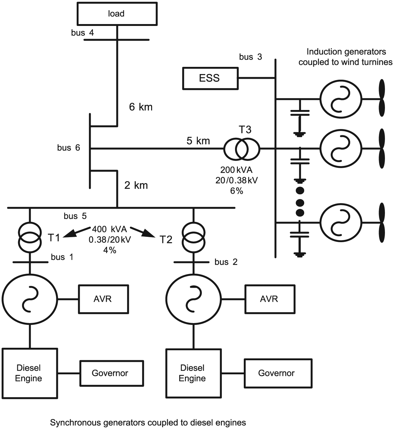
Block diagram of hybrid wind–diesel system.
Modelling of wind–diesel system
Modelling of wind turbine model
The operation of the machine depends on the sign of the torque and slip (negative for generator mode and positive for motor). The mechanical model is determined by the electromechanical equation known as swing equation

Modelling of induction generator
Induction machine is modelled by a Thevenin’s equivalent circuit of a voltage

Rotor equations are


Torque developed by the induction machine is given in equation (5)

where


To reduce the number of differential equations, it is assumed that the wind generators operating under the same wind conditions are replaced by an equivalent single machine. The parameters of a single equivalent machine are then given by the following relations

Diesel engine and speed governor
Diesel engine is modelled by a first-order transfer function model with time constant TD in which the small delay involved between actuator oil injection and production of mechanical torque is neglected (Stavrakakis and Kariniotakis, 1995). Both the synchronous generators are coupled with IEEE type 1 AVR (Stavrakakis and Kariniotakis, 1995).
Modelling of synchronous generator
Synchronous generator is modelled using stator equation in algebraic form and rotor equations in differential form as shown in equations (9) to (12)


where
Load, capacitor bank and transmission line modelling
When active power (PL), reactive power (QL) and voltage Vt is known, loads can be modelled as admittance given by

Capacitors which are required for reactive power compensation of induction generators are modelled by incorporating their reactance Xc in network admittance matrix. Similarly, knowing the transmission line characteristics (RT, LT, CT) per unit length, they are converted into the line admittances and are incorporated into the network admittance matrix (Serdar et al., 2015).
ESS as current source
Connection of an ESS to a typical power system bus is shown in Figure 2 where PESS and QESS are, respectively, the active and reactive powers injected by ESS, V is the bus voltage and IESS is the current injected by ESS.
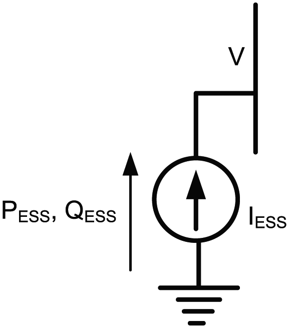
Current source representation of ESS.
Basically, when an ESS is integrated with an alternating current (AC) system through a suitable power conversion system, it can be controlled to exchange active and reactive power with the system in four quadrants of P–Q plane. The active power, reactive power supplied by the ESS, the voltage of the bus to which ESS is interfaced and the current injected by storage system on AC side are related through the following equation

Equation (14) in DQ component from the study of Hiyama et al. (2005) turns out to be

where VD, VQ are the direct and quadrature axis voltages of the bus where ESS is connected. PESS and QESS are the active and reactive powers delivered/absorbed by ESS and are used to calculate the currents injected by energy storage as shown in Figure 3. ESS active and reactive power output (PESS and QESS) are the outputs of ESS controlled converter. ESS converter is represented by a first-order time lag compensator (Wu et al., 2012) whose transfer function G(s) is given by equation (16)

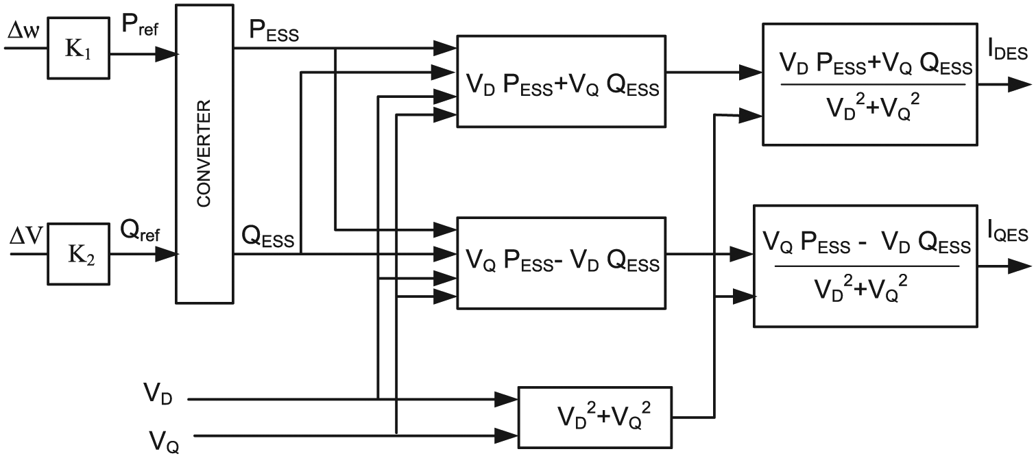
Current injected by ESS.
Pref and Qref shown in Figure 3 are proportional to the deviation in frequency (∆ω) and voltage (∆V), respectively (Ngamroo et al., 2009), and are given by equations (17) and (18)


Solution of network, machine stator equations and incorporation of ESS
In order to reduce the complexity of the system and make the modelling of the system simple, order of the admittance matrix is reduced to the number of generators in the system. In this article, we have considered three machines with two synchronous generators connected at bus 1 and a single equivalent induction machine connected at bus number 3. ESS is also connected at bus number 3 as a controllable current source which acts as a sink/source of both active and reactive power. The order of the reduced bus admittance matrix in this article is three because three machines are considered. Network equation for hybrid system relating the bus bar voltages with the injected currents in the synchronous reference frames is given by equation (19)

where n = 3
In DQ component (synchronously rotating reference frame), one can write the above equation as
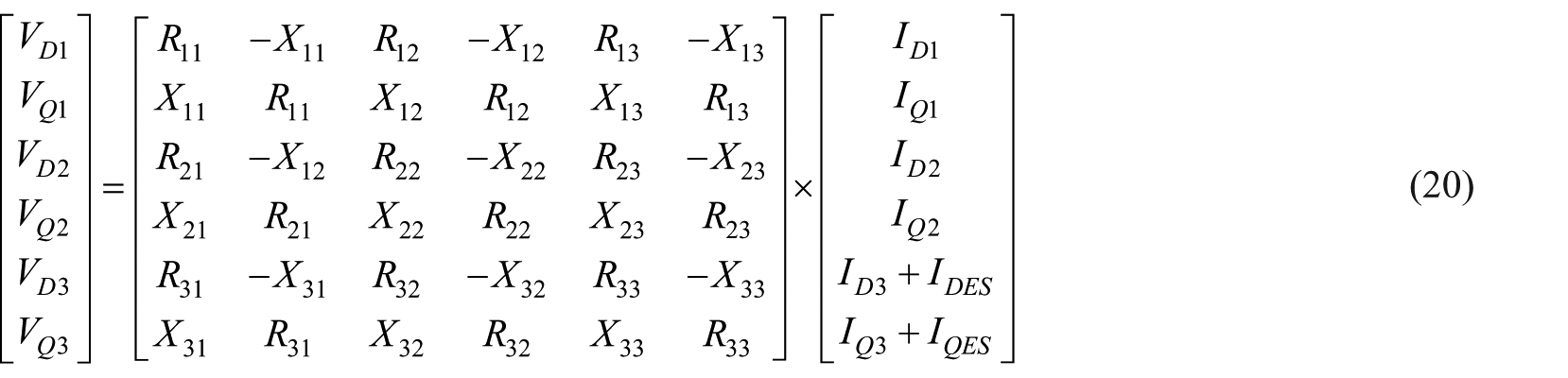
Representing equation (20) in matrix form gives equation (21)

where
Equation (9) can be converted into synchronously rotating reference frame for both the synchronous generators as shown in equation (22)
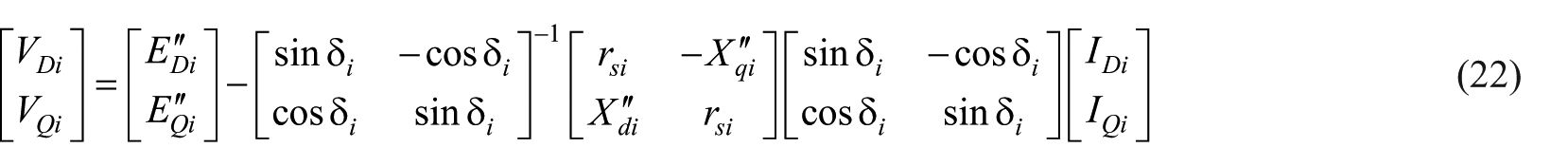
where i represents the number of synchronous generators in the system. Substituting equations (22) and (9) in equation (20), we get equation (23) as shown

where
In this article, the frequency of the system is estimated using the concept of COI, where frequency computation is carried out using rotor speed and inertia constant of the connected synchronous generators in the system using equation (24), where G represents a synchronous generator set, ωj is rotor speed and Hj is inertia constant (Mufti et al., 2017; Ortega Milano, 2016)

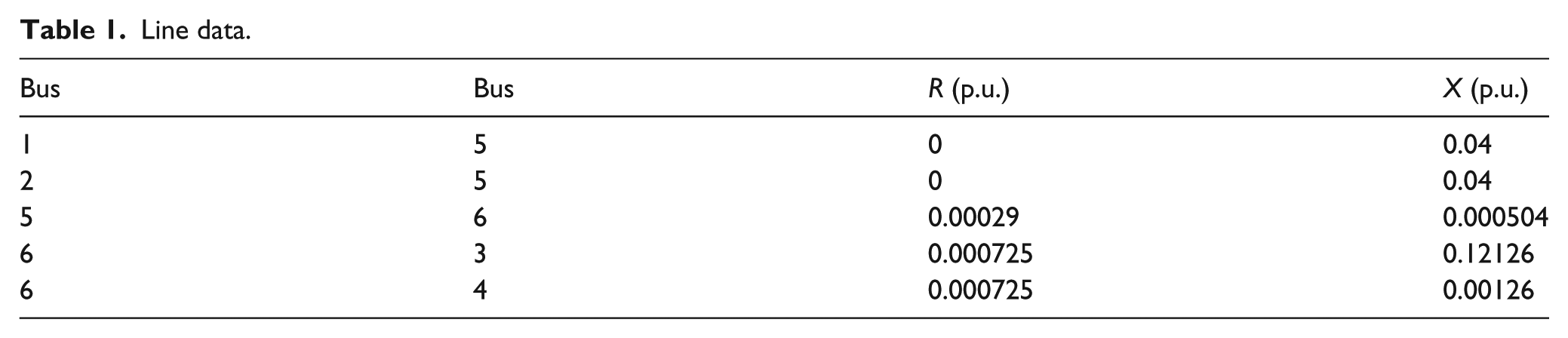
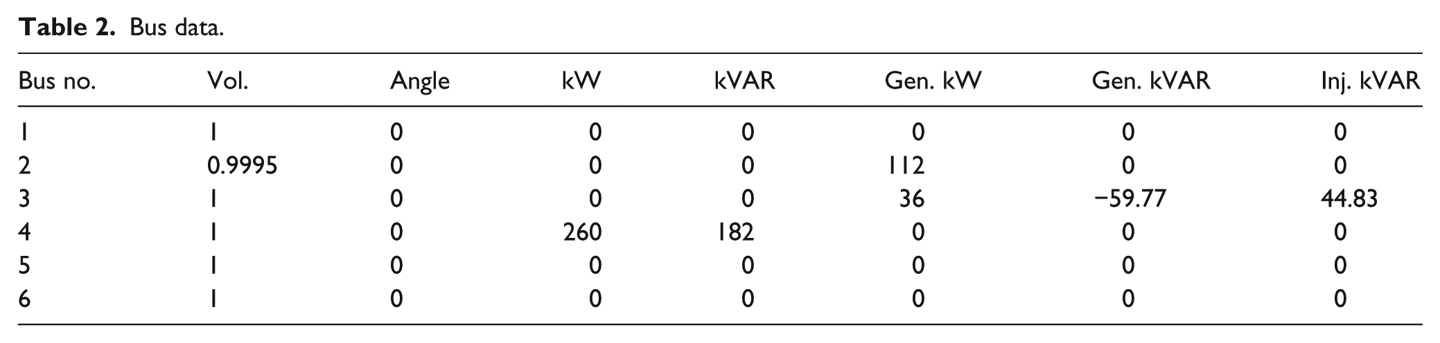
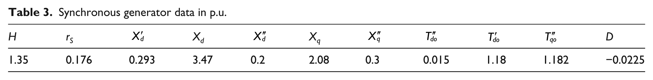
System base is assumed to be 400 kVA and frequency is 50 Hz. The data pertaining to various lines, buses, synchronous generators, IEEE type 1 AVRs, diesel engines, equivalent induction generator and ESS are given in Tables 1 to 7.
Line data.
Bus data.
Synchronous generator data in p.u.
Automatic voltage regulator data in p.u.
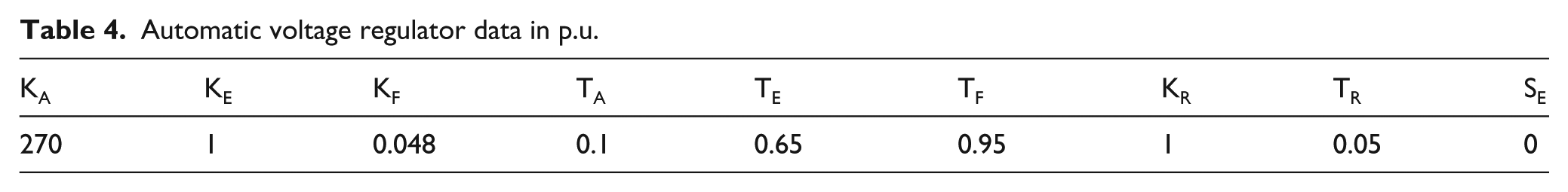
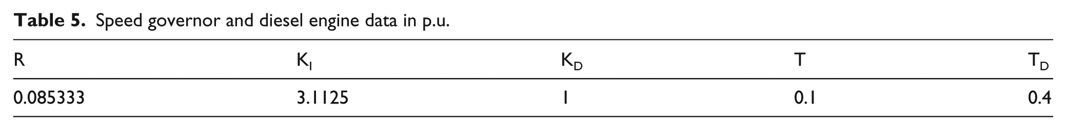
Speed governor and diesel engine data in p.u.
Induction generator data in p.u.

ESS data.
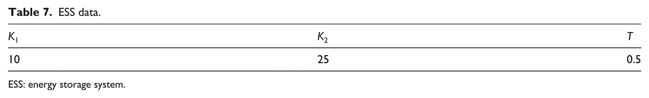
ESS: energy storage system.
Modified load flow analysis
To create a steady-state scenario for wind–diesel system, the wind power (Pm) production is considered to be known to the management service of the wind energy conversion power station and to the services of diesel power station. Turbines are considered as generating units with active power positive and reactive power negative in load flow analysis. Newton Rapson method is applied to solve the load flow because of its good convergence properties. Load flow program interacts with a routine, so that in addition to normal load flow results, the initial slip of equivalent induction machine is also obtained. Some details of the routine regarding the slip and other initial condition computation of induction machine are obtained as following.
First, the rotor differential equations of induction machines are considered and their derivatives are set to zero for obtaining steady state. After solving these equations along with equations (7) and (8), the following equations for active power, reactive power and slip are obtained


The roots of equation (26) are calculated and among the real ones, the one with the maximum value is chosen to be the value of induction generator slip but with negative sign. Initial value of voltage is not known because the reactive power should be inputted to the load flow program. To solve this, first C is calculated for V3 = 1 p.u. The value of C is substituted in equation (26) to obtain the value of slip, which is then substituted in equations (13) and (25) to obtain QAe which is fed to load flow program, and results are obtained. Generally, the value of voltage is different from 1 p.u.; the new value of QAe calculated on the basis of new voltage, obtained from the load flow results, is a better approximation. The algorithm for load flow analysis of hybrid power system comprising both synchronous and induction machines is shown in the flowchart as shown in Figure 4.
Flowchart for modified load flow engine.
Initial conditions for dynamic analysis
The steady-state values of the state variables for a multi machine model are computed by systematically solving the load flow equations of the model including synchronous as well as asynchronous machine and then computing the other algebraic and state variables. For steady-state analysis, all the derivatives of the state variables are set to zero in the differential equations, which after solving give the initial value of the state variable. The initial values of the state variables thus obtained are given in Table 8.
Initial conditions of three-machine six-bus system.

Simulation studies
The load flow results are shown where in addition to normal load flow results, initial value of slip of induction generator is also obtained.
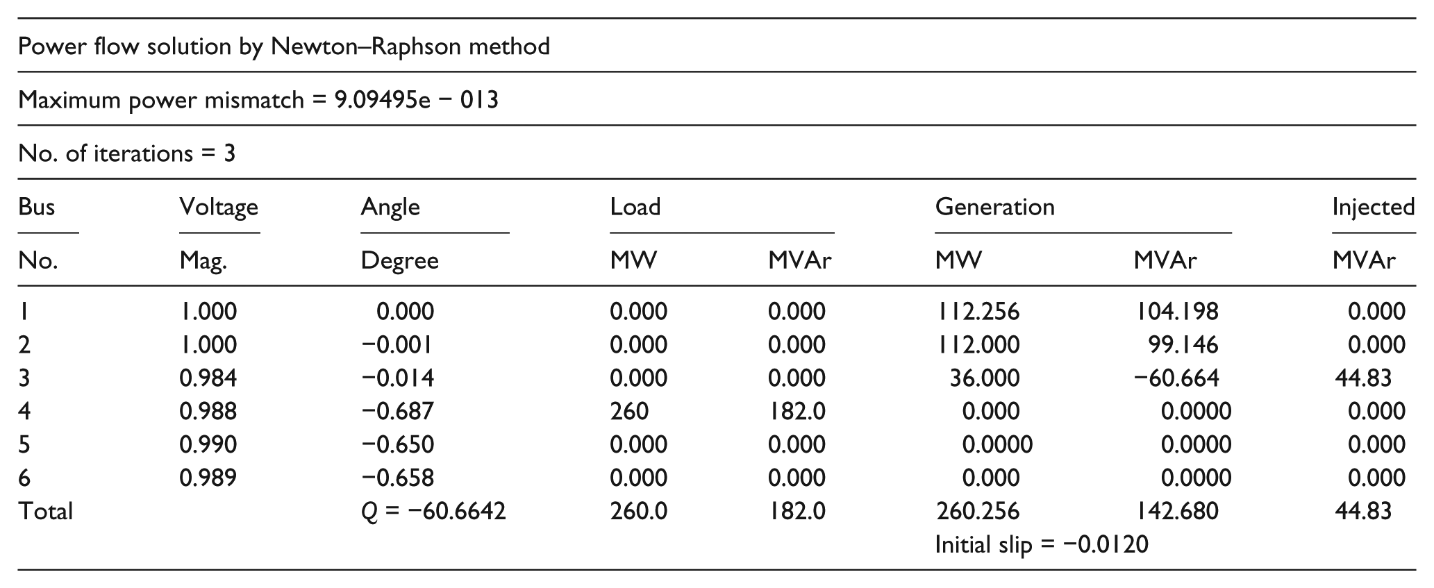
Before the onset of disturbances, the system is considered to be in steady state – power supplied by wind turbines is 36 kW, and the total load is 260 kW and 182 kVAR. System frequency is nominal, that is, 50 Hz, and voltages at various buses are as shown in load flow results given above. Results of load flow are used for calculating bus admittance matrix Ybus. To make calculations easy, order of bus admittance matrix is reduced from 6 to 3 using Kron’s reduction technique. This gives reduced bus admittance matrix Yred.
System is subjected to two types of disturbances, that is, load disturbance and wind gusts. In the first case study, a load disturbance of 10% (both active and reactive) is introduced into the system at time t = 0+ sec. Time before t = 0 s, system was assumed to be in steady state, that is, frequency deviation is zero. The results of reduced bus admittance matrix for nominal load (Yred1) and for a load disturbance of 10% (Yred2) are shown as

The frequency deviation of the synchronous generators with a load disturbance (both active and reactive) of 10% is shown in the form of wave in Figure 5 (with and without energy storage). With the change in load, bus admittance matrix changes. Pre-disturbance load of the system is assumed to be 260 kW and 182 kVAR. At time t = 0+ s, load is reduced to 234 kW and 163.8 kVAR which increases the frequency (Figure 5) and voltage (Figures 6 and 7). At time t = 10+ s, load is increased back to 260 kW and 182 kVAR. This decreases the frequency as well as voltage of the system. Again at time t = 20+ s, load is reduced resulting in rise in frequency and voltage. Figures 5 to 7 show that there is a considerable reduction in frequency and voltage deviation using ESS. Figure 8 shows the currents, that are injected by ESS under load disturbance where currents injected by ESS changes under load disturbance. Figure 6 shows the variation of voltage at bus 3 where equivalent induction machine is connected, and Figure 7 shows the variation of voltage at bus 1 where synchronous generator is connected. All the figures demonstrate that better results are obtained by incorporating an ESS in the system. Since there is no AVR at induction generators’ bus, a reactive load disturbance of step type in the system will result in a steady-state voltage deviation at induction generators’ bus as depicted in Figure 6. However, at a synchronous generator bus, the presence of an AVR results in zero steady-state error in voltage, as shown in Figure 7.

Frequency response of system under load disturbance.

Voltage at bus number 3 under load disturbance.
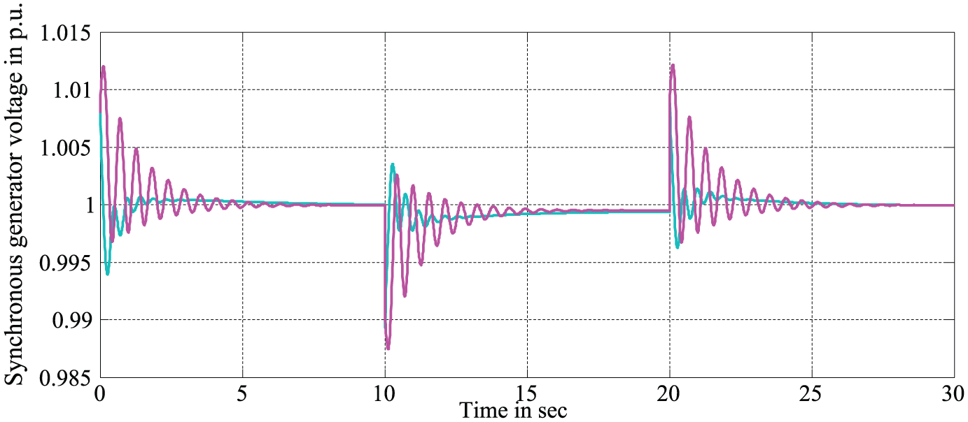
Voltage at bus number 4 under load disturbance.
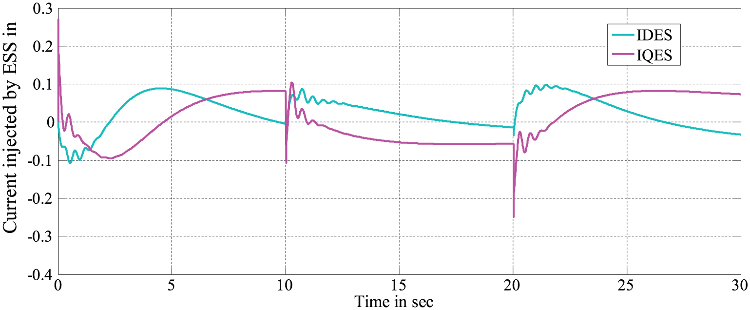
Current injected by ESS under load disturbance.
In the second case, system is subjected to continuously varying wind gust for a time period of 14 s. Figure 9 shows the randomly varying wind turbine torque because of wind gust, and the frequency response is shown in 10. Figure 10 shows that with the ESS, the frequency deviation of the system under wind gust is reduced considerable. Figure 11 shows the currents injected by ESS where both DQ components of current are shown. Figure 12 shows the voltage at bus 3 with and without energy storage, while Figure 13 shows the synchronous generator voltage with and without energy storage. Results shown in Figures 10, 12 and 13 clearly establish the effectiveness of ESS in improving the supply quality. It can be inferred that maximum deviation and oscillatory nature of system frequency and voltages are considerably reduced with the ESS. Figure 11 shows the D and Q components of current injected by ESS. The fluctuations in these variables are the result of continuous active and reactive power exchange of ESS with the wind–diesel system under the turbulent wind conditions, to bring about significant improvement in the system dynamic performance.
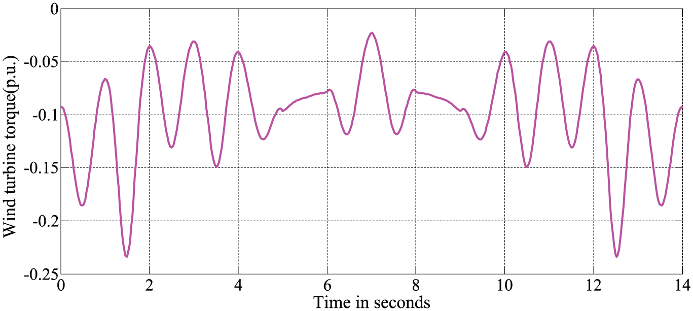
Wind turbine torque under wind gust.
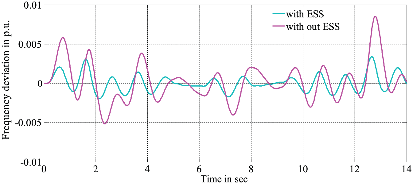
Frequency deviation of system under wind gust.
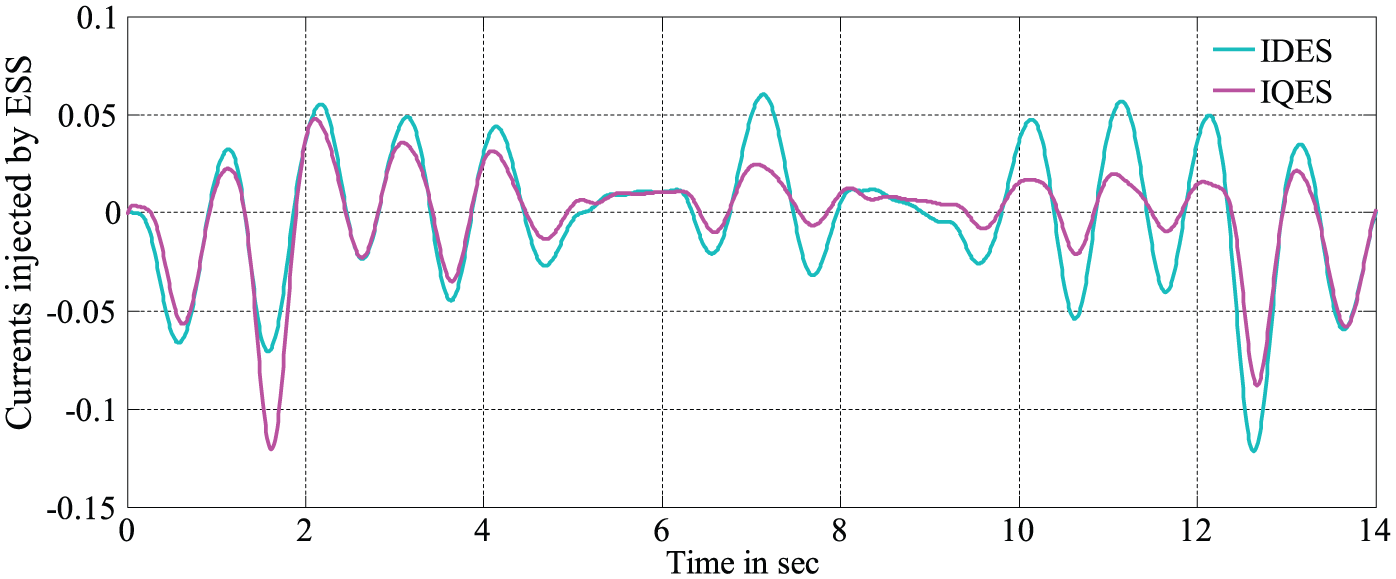
Current injected by ESS under wind gust.
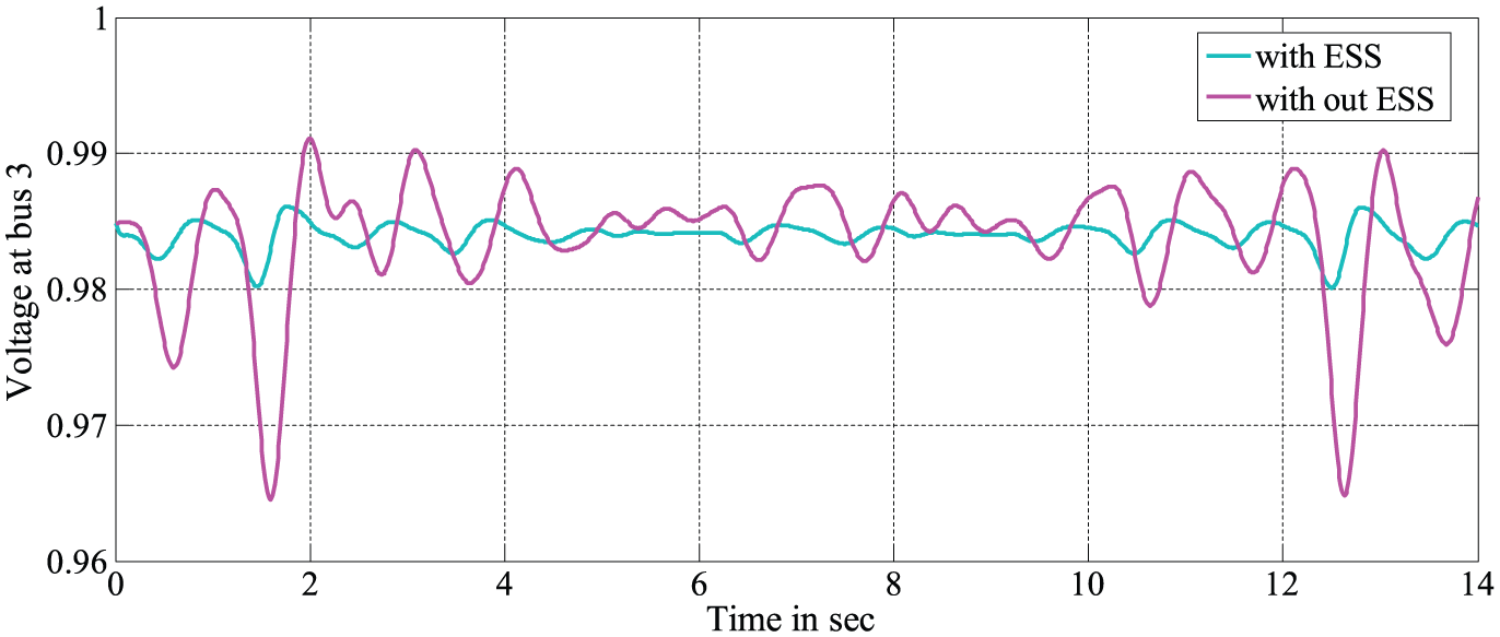
Voltage at bus 3 under wind gust.
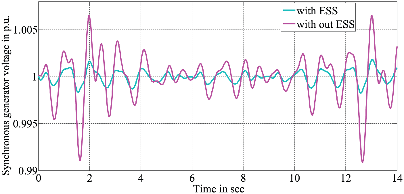
Synchronous generator voltage under wind gust.
Figures 5 to 7, 10, 12 and 13 reveal that in both the case studies, the maximum deviations in frequency and voltages as well as their oscillatory behaviours are considerably reduced when ESS is introduced at induction generators’ terminal bus.
Conclusion
A comprehensive MATLAB/Simulink model of a hybrid wind–diesel storage system is developed. ESS is modelled as a controllable current source which injects/absorbs both real and reactive components of current into the system. Modified load flow program for calculation of initial value of slip for induction machines has been developed. The performance of the compact model comprising machine model, ESS and network model is tested for both wind as well as load disturbance. Comparison of the simulation results obtained for the system with and without ESS demonstrates that improved power quality results are obtained by incorporation of ESS. The comprehensive model developed can easily accommodate the detailed dynamics of any type of ESS.
Footnotes
Appendix 1
Declaration of conflicting interests
The author(s) declared no potential conflicts of interest with respect to the research, authorship and/or publication of this article.
Funding
The author(s) received no financial support for the research, authorship and/or publication of this article.