
Abstract
In this article, a comprehensive model for power quality assessment of a standalone wind-diesel-superconducting magnetic energy storage system is developed using firing angle control scheme of superconducting magnetic energy storage unit. A four-quadrant operation of superconducting magnetic energy storage unit is proposed where firing angle of superconducting magnetic energy storage converter is controlled depending upon active and reactive power demand of wind-diesel system, under various disturbances. Superconducting magnetic energy storage is designed as a controllable current source capable of reducing both frequency and voltage deviations simultaneously. For continuous control of superconducting magnetic energy storage unit, a regulating variable is formulated which forces the superconducting magnetic energy storage current to return to its nominal value after handling a disturbance in order to handle a new disturbance. Frequency of the system is estimated using the concept of centre of inertia. System performance is assessed for disturbances of higher magnitudes. Complete modelling is carried out in MATLAB/Simulink environment, and simulation results demonstrate that the scheme gives expected results under load disturbance and wind perturbations.
Keywords
Introduction
Renewable energy sources are widely being used because of their outstanding advantages over conventional energy sources. Among all the renewable energy sources, wind energy conversion system (WECS) is the most popular and fast growing. WECS-based power systems are most suitable for habitations which are not grid connected or where power is supplied from diesel-generating units. The integration of wind power system with the already existing diesel-generating system increases the reliability of the power system and reduces the cost of fuel (Das et al., 1999; Kusakana and Vermaak, 2014). Integrating a WECS with a diesel-generating system is, however, a challenging task. Since the inertia is low, any disturbance in the system will cause electromechanical oscillations and deteriorates the power quality (Salih et al., 2014; Sheikh et al., 2009). Power quality problem can, however, be solved by incorporating a superconducting magnetic energy storage (SMES) unit as buffer storage. Advantage of SMES is that it is fast acting with almost zero self-discharge. The coil is kept at a very low temperature with the help of cryogenic coolers, so the ohmic losses are close to zero during the operation. System of this type can charge and discharge very fast and has the ability to absorb or deliver high quantities of power. Another important aspect of SMES is its long life and it has millions of charge and discharge cycles (Iqbal et al., 2009; Moschakis et al., 2005; Nielsen and Molinas, 2010).
SMES being a fast-acting device is capable of absorbing/releasing both active and reactive power by properly controlling the firing angles of the power conditioning system (Hsu, 2002). Due to change in wind speed and load disturbance, any variation in active and reactive power will interact with network, provoking frequency, and voltage deviation (Ali et al., 2005). SMES has been used in wind-based power system for stability enhancement with no emphasis on frequency and voltage deviation control. In the work by Hemeida (2010), frequency control of a two-area power system using fuzzy-based controller for an SMES unit is proposed but voltage control is neglected. In the work by Zargar et al. (2017a), a simple model for a generalised energy storage system is presented for simultaneous voltage and frequency control in a wind-diesel power system. Although energy storage system is modelled as a controllable current source, yet details related to switching control scheme are not considered for power conditioning system. In this article, an SMES unit is used for controlling both frequency and voltage deviations. Four-quadrant operational control for simultaneous active (P) and reactive (Q) power exchange of SMES unit with the wind-diesel system is developed. A detailed model of SMES unit along with its power conditioning system is described where SMES is modelled as a controllable current source which injects both active and reactive components of current into the system by suitably controlling the firing angles of the SMES converters. Also, a suitable regulating variable is chosen to ensure continuous control. Network model is developed using MATLAB function available in the Simulink library and is integrated with the machine and SMES model along with their control systems to form a compact model. System considered comprises two synchronous generators of equal rating with automatic voltage regulator (AVR) and speed governor, eight squirrel cage induction machines driven by wind turbines are represented by a single equivalent induction machine, loads are represented as admittances, and capacitor bank used for reactive power compensation of induction machine are modelled by equivalent admittances. Block diagram of the system is shown in Figure 1. SMES is installed at bus number 4 where load is connected. Modelling of wind-diesel system, network modelling, and SMES are discussed. Simulation results demonstrate the potency of the proposed scheme.

Block diagram of hybrid wind-diesel-SMES system.
Modelling of wind-diesel system
Modelling of wind turbine model
Mode of operation of induction machine depends upon the sign of torque and slip, that is, negative for generator and positive for motor. Swing equation which represents the mechanical model is given by equation (1)

Modelling of induction generator
Induction machine is modelled by a voltage source E′ behind stator resistance rs and transient reactance X′. Stator equations are expressed in synchronously rotating reference frames in a matrix form in equation (2) and rotor equations are given by equations (3) and (4)


Torque developed by the induction machine is given equation (5)

Voltage, current, active, and reactive power output are given by equations (6)–(8)


The parameters of a single equivalent machine are then given by the following relations

N is the number of induction machines used, which is 10 in this article.
Diesel engine and speed governor
Diesel engine is modelled by a first-order transfer function model with time constant TD (Stavrakakis and Kariniotakis, 1995), and IEEE type 1 AVR is used for both the synchronous generators (Stavrakakis and Kariniotakis, 1995).
Modelling of synchronous generator
Synchronous generator is modelled using equations (9)–(12)


Load, capacitor bank, and transmission line modelling
When active power (PL), reactive power (QL), and voltage (Vt) is known; load can be modelled as admittance given as follows

Capacitors for reactive power compensation and transmission line parameters such as resistance per unit length, capacitance per unit length, and inductance per unit length are converted into admittances and are incorporated into the network admittance matrix (Serdar et al., 2015).
Four-quadrant operation of SMES
Currents supplied by SMES unit (IDSMES and IQSMES) are calculated using the active and reactive powers supplied by SMES as shown in equation (14) (Hiyama et al., 2005)

VD and VQ are the direct and quadrature axis voltages of the bus, respectively, where SMES is connected.
PSMES and QSMES are the active and reactive powers delivered/absorbed by SMES and are used to calculate the currents injected by SMES as shown in Figure 2.
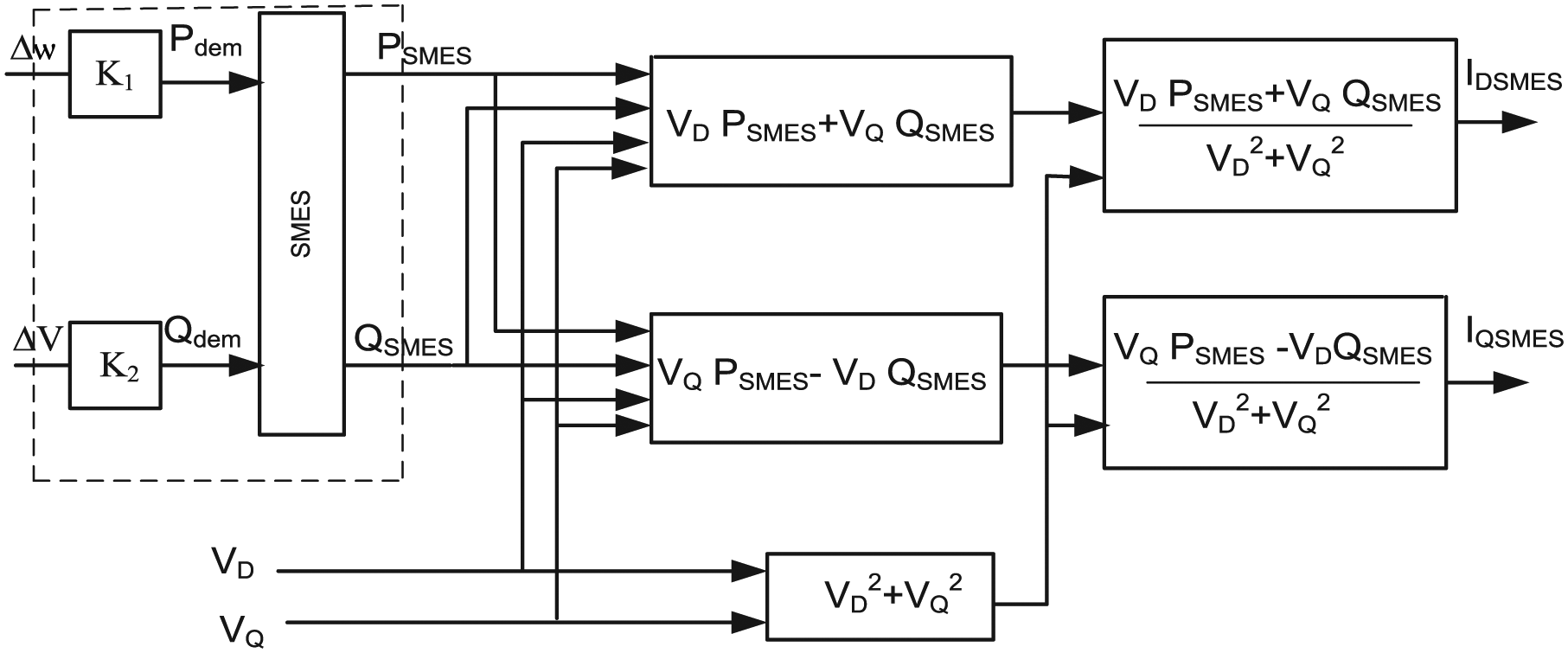
Current injected by ESS.
Pdem and Qdem shown in Figure 2 are proportional to the deviation in frequency (∆ω) and voltage (∆V), respectively (Ngamroo et al., 2009) and are given by equations (15) and (16)


Pdem and Qdem are actually the active and reactive power demands of wind-diesel system which are used to calculate the firing angles of SMES converter. In this article, two sets of gate turn-off thyristors (GTOs) are used as shown in Figure 3, where ∆-Y and ∆-∆ transformers make a 12-pulse arrangement. Direct current (DC) ripple voltage is reduced because the high side voltage and current in Y-∆/∆-Y transformers lead the low side voltage by 30° for positive sequence, and the high side voltage and current lag the low side by 30° for negative sequence. In Figure 3, P1, Q1 and P2, Q2 are the active and reactive powers of converters 1 and 2, respectively, and are related to Pdem and Qdem by the following equations


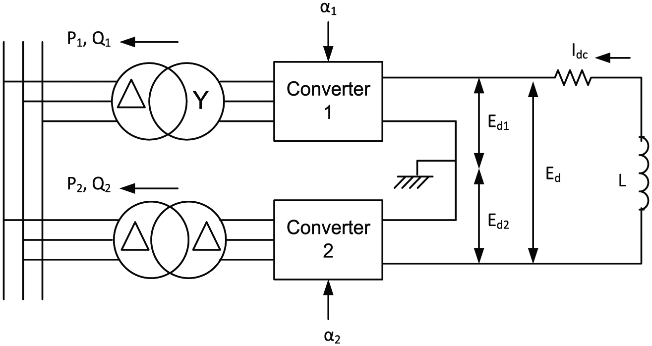
SMES with two converters.
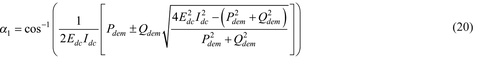
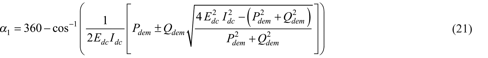
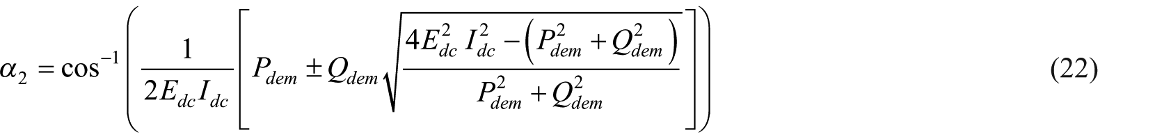
Since two sets of GTO converters are used, the possible regions of firing angles of the converter are from 0° to 360°. At first, the region where the (Pdem, Qdem) point lies is located using Figure 4. Next, the calculation of firing angles α1 and α2 is done using equations (20)–(23). In case Pdem = Qdem = 0, infinite number of the combinations of α1 and α2 exist and one of the solution is α1 = 90° and α2 = 270°. Using equations (20)–(23), four-quadrant operation of SMES is achieved. Figure 4 shows the control domains of GTO converters where the control domains are determined as follows:
Area I – use equations (20) and (23) with lower side complex sign.
Area II – use equations (20) and (22) with upper side complex sign.
Area III – use equations (20) and (23) with upper side complex sign.
Area IV – use equations (21) and (23) with upper side complex sign

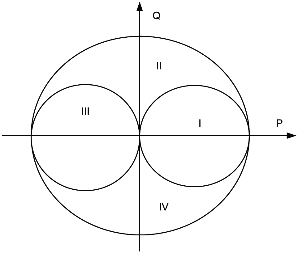
Power control domain of GTO converters.
Converter output voltage, SMES current, active, and reactive power supplied to SMES are calculated using the following equations (Ali et al., 2005)


Simulink model for calculating PSMES and QSMES is shown in Figure 5. IDSMES and IQSMES obtained from equation (14) are injected at bus number 4 as expressed by equation (28)

where


Simulink model for SMES active and reactive power.
In order to achieve continuous control of active power, a regulating variable y(k) is formed which forces the SMES current to return to its nominal value after handling a disturbance so that the SMES unit remains ready to tackle a new disturbance. The regulating variable ‘y’ is chosen to be a function of frequency deviation and SMES current deviation given by expression equation (31)

where the active power demand Pdem is proportional to frequency deviation, Ido is the nominal current of the SMES unit. The second term on the right-hand side of equation (31) is introduced to force the SMES coil current to return to its nominal value after dealing with a disturbance. The value of constant kc is properly chosen. The large value of kc will make SMES unit ineffective in reducing the frequency deviations. On the other hand, very small value of kc will not allow the SMES coil current to return to its nominal value (Zargar et al., 2017b).
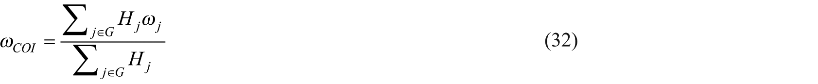
The frequency of the system is estimated using the concept of centre of inertia, where frequency computation is carried out using rotor speed and inertia constant of the connected synchronous generators in the system using equation (32), where G represents a synchronous generator set, ωj is rotor speed and Hj is inertia constant (Mufti et al., 2017; Ortega and Milano, 2016)
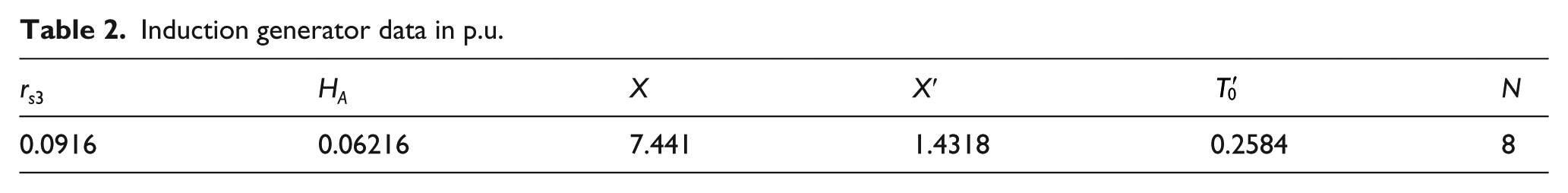
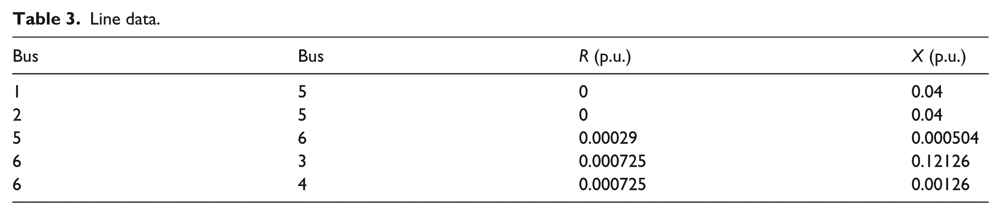
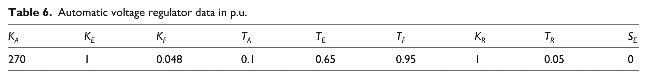
System base is assumed to be 400 kVA and frequency is 50 Hz. The data pertaining to SMES unit, equivalent induction generator, various line, buses, synchronous generators, IEEE type 1 AVRs, and diesel engines are given in Tables 1 to 7.
SMES data.

Induction generator data in p.u.
Line data.
Bus data.

Synchronous generator data in p.u.

Automatic voltage regulator data in p.u.
Speed governor and diesel engine data in p.u.

As shown in Figure 1, SMES unit is installed at load bus, that is, bus number 4. To reduce the computational time, order of the bus admittance matrix is reduced from 6 to 4, resulting in a reduced bus admittance matrix (Yred). Initially, the system is assumed to be in steady state with frequency and voltage deviations equal to zero. In this article, two types of disturbances are considered:
Load disturbance;
Wind perturbations.
In the first case, study system is subjected to a load disturbance (both active and reactive) at times t = 0 s, t = 20 s, and t = 40 s. At time t = 0 s, load is reduced by 10%; at time t = 20 s, load is increased to its rated value; and at time t = 40 s, load is again reduced by 10%. Reduced bus admittance matrices corresponding to load changes are shown as Yred2 and Yred1


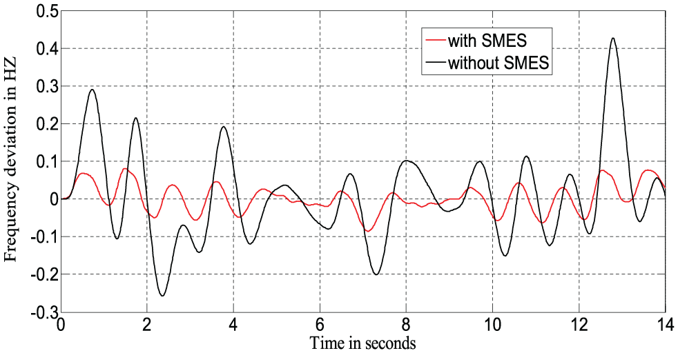
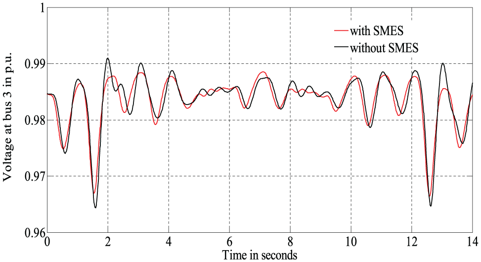
Pre-disturbance load of the system is assumed to be 260 kW and 182 kVAr. Frequency and voltage deviations because of load change are shown in Figures 6 to 9.
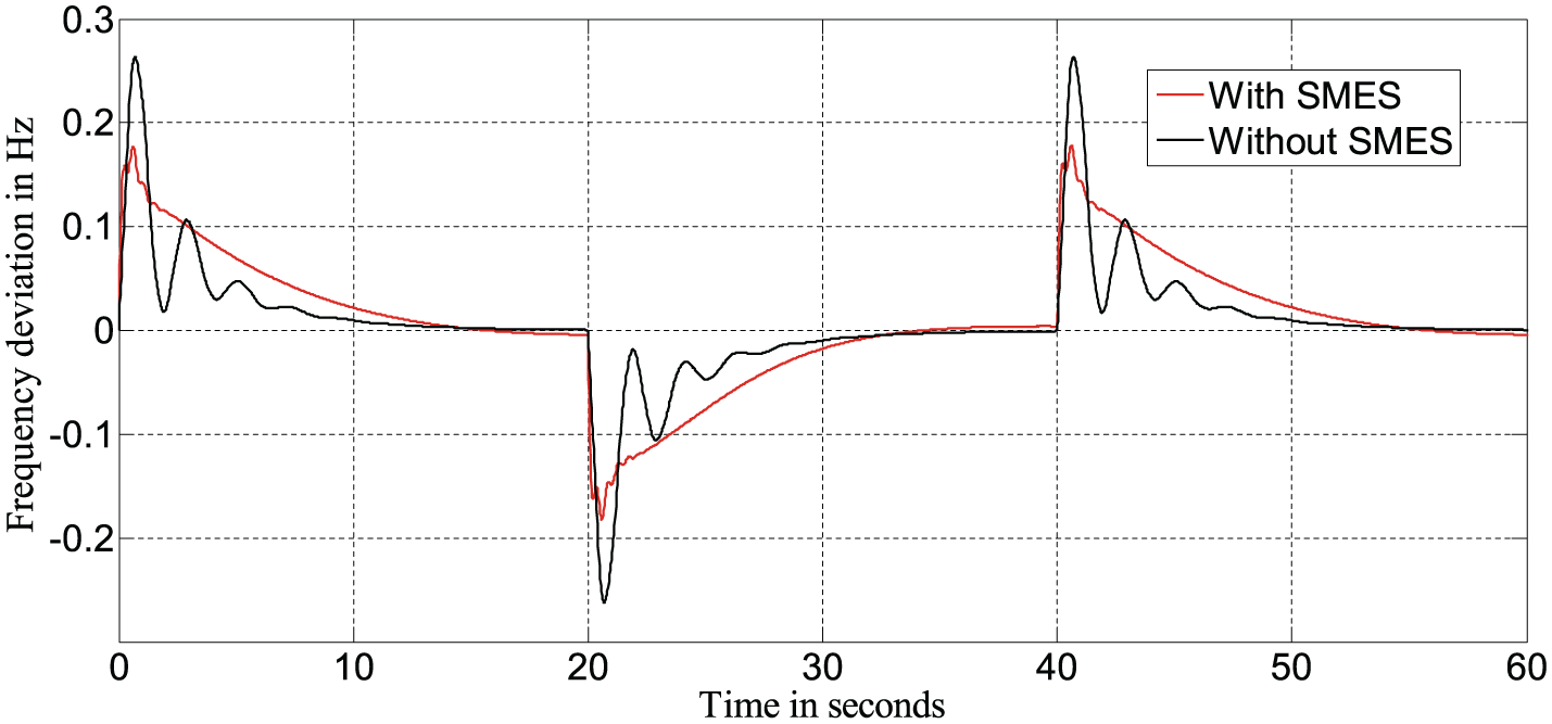
Frequency response of system under load disturbance.

Voltage at bus number 1 under load disturbance.
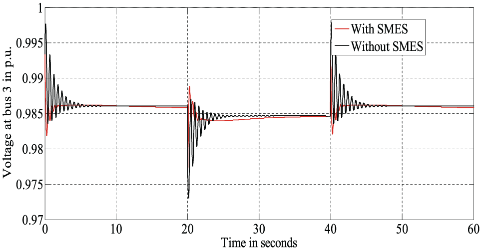
Voltage at bus number 3 under load disturbance.
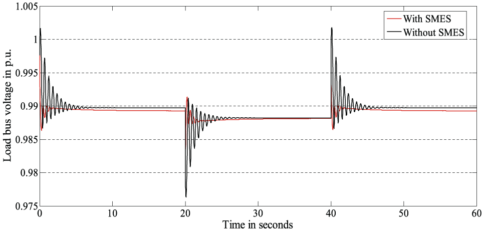
Voltage at load bus under load disturbance.
Variation of SMES current (Idc) and currents injected by SMES unit (IDSMES, IQSMES) are shown in Figures 10 and 11.

SMES current under load disturbance.
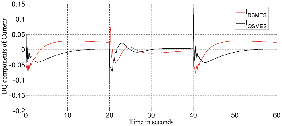
Currents injected by SMES under load disturbance.
In the second case, study system is exposed to a continuous wind perturbation of the form shown in Figure 12. Frequency and voltage deviations are shown in Figures 13 to 16.

Wind turbine torque under wind gust.
Frequency response of system under wind perturbation.

Voltage at bus number 1 under wind perturbation.
Voltage at bus number 3 under wind perturbation.
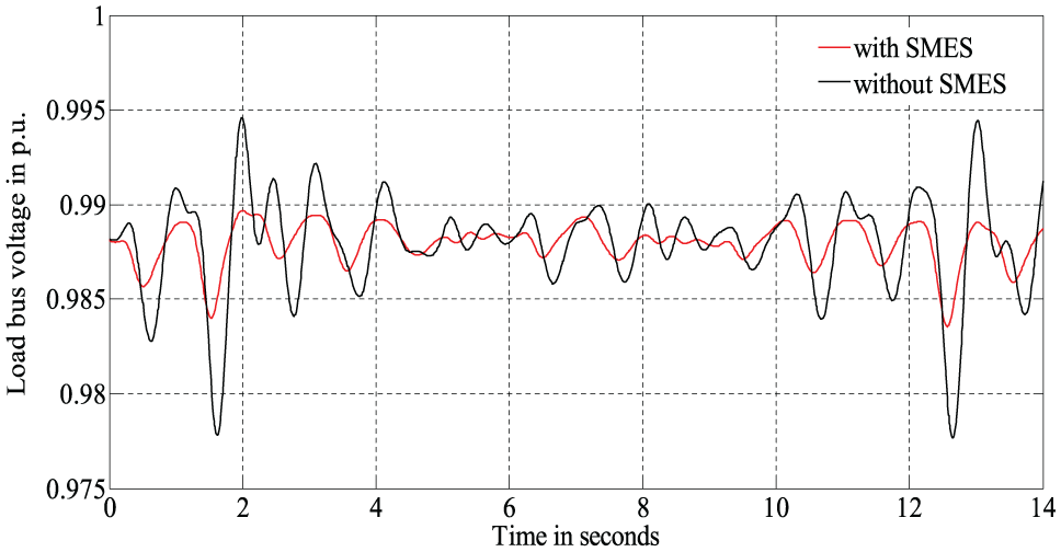
Voltage at load bus under wind perturbation.
Currents injected by SMES unit into the system are shown in Figure 17.

Currents injected by SMES under wind perturbation.
Results in these figures show the following:
Peak frequency and voltage deviations are reduced considerably both under load disturbance and wind perturbation. These figures also show that oscillations in frequency and voltages are damped out quickly by incorporation of SMES unit.
In case of wind perturbation, there is a significant improvement in voltage at load bus as compared to induction generator bus. It is because SMES unit is installed at load bus.
Figure 10 shows that the SMES current returns to its nominal value after handling a disturbance because of the regulating variable y(k). However, in case of wind perturbation, it is not possible because wind torque is continuously changing.
For time t = 0 s to t = 20 s, load is decreased by 10% which results in the rise in frequency and thus SMES unit should charge which is evident by the increase in SMES current during this time period. Between 20 and 40 s, load is increased to its rated value and thus SMES is discharging which is evident by the decrease in SMES current.
Figures 11 and 17 show the currents injected by SMES unit into the wind-diesel system.
Conclusion
A comprehensive MATLAB/Simulink model of a hybrid wind-diesel-SMES system is developed. SMES is modelled as a current source capable enough to keep frequency and voltage deviations to minimum. In case of load disturbance, frequency deviation is reduced by almost 37%, and for wind perturbation, frequency deviation is reduced by 82%. Apart from active and reactive power balance, continuous control is also achieved by SMES unit. The performance of the compact model comprising machines, load, and SMES is tested for both wind and load disturbance. Comparison of the simulation results obtained for the system with and without SMES demonstrates that improved power quality results are obtained by incorporation of SMES unit.
Footnotes
Appendix 1
Declaration of conflicting interests
The author(s) declared no potential conflicts of interest with respect to the research, authorship, and/or publication of this article.
Funding
The author(s) received no financial support for the research, authorship, and/or publication of this article.