




Abstract
Rolling bearings are universally adopted to serve as revolute joints in almost all mechanisms or machines, because they offer a convenient solution to the problem of minimizing friction and, simultaneously, providing a large load-carrying capacity at any kinematic regime, including slow or alternate rotations. However, in offshore wind turbines not only they reach large dimensions but also they move within strong electromagnetic fields created by the turbine generators. For example, considering the last amplification stadium epicyclic gearbox, they may serve to sustain elements rotating around floating shafts (planetary) which also move around a fixed principal shaft (solar). This article illustrates an original experimental test bench that simulates sliding and rolling contacts through which a test current is flowing. Unexpected and interesting results disclose how this particular field is challenging and how more investigations are still required to achieve an adequate and complete interpretation. The understanding of this phenomenon could give rise to modification to the composition and the microstructure of rollers and rings employed in offshore wind turbines.
Introduction
The behavior of a pair of tribo-elements with sliding and rolling contact has been extensively studied in literature as an important branch of Tribology. Both experimental and theoretical works have been dedicated to a huge amount of applications. In order to name a few of them, and only those which the authors have been involved into, it is worth noticing how the variety of the applications has been extended to very different fields, such as special transmissions (Belfiore and De Stefani, 2003; Belfiore et al., 2006a), gears (Belfiore, 2004; Belfiore et al., 2006b), metal forming (Belfiore et al., 2007), cold rolling (Bolt et al., 2010), and microsystems (Belfiore et al., 2014). However, more recently, the applications where an electric current is induced to flow through a pair of tribo-elements have received a certain attention in literature. The influence of current flowing through a contact is particularly evident in electric railway vehicles pantograph, where an arc discharge takes place on the contact strip, and in electric motor brushes. For these reasons, a certain attention has been paid to the behavior of such tribo-systems.
Since 1978, current flow through tribological contacts has been investigated on copper-graphite brushes at high speeds (160 m/s) and high current densities (870 A/cm2; Casstevens et al., 1978). Although the presence (or absence) of electric current flow appeared to have a limited impact on the measured wear rate, some interesting results have been found. For example, for the same speed, the positive brush appeared to be less exposed to wear than the negative one. Moreover, the contact electrical resistance appeared to be decreasing with increasing loads. The effects of current on friction and wear in powder metallurgy brushes have also been studied in another investigation (Feng et al., 2005), where, through scanning electron microscope (SEM) observations, current appeared to stimulate roughness and abrasion.
A tribo-tester with metal-impregnated carbon strip under electric current has been used (Hu et al., 2009) to simulate the working conditions of the pantograph wire, and SEM, energy-dispersive X-ray spectroscopy (EDS), and X-ray diffraction (XRD) have been used to analyze microstructure and phase composition. Results showed that locally temperature may increase beyond material melting point, inducing material transfer, melt, and sputter erosion. Other experimental activities performed on a pin-on-disk (Ding et al., 2009a) showed that spark or arc discharge is dominant when the pin is connected to the power supply cathode or anode, respectively, showing an interesting dependency on the nature of the electric charge. These results have been useful to reduce off-line discharge of pantograph-catenary systems. Strip-wire contact vibrations have been experimentally studied (Yang et al., 2015) by means of a block-on-ring tribometer under high-speed and high electric current density conditions. Results showed that while speed makes worse the vibrational state, the current allows the contact surface temperature between the strip and contact wire to grow faster, with subsequent increase in arc erosion and delamination.
Later, more attention to the effects of current flow in contact mechanics has been paid to understand more general properties of this phenomenon. In 2001, a tribo-test stand has been used to investigate about current flowing through carbon-graphite contact with up to 75 m/s sliding speed and 100 A intensity (Zhao et al., 2001). Using different values of load, sliding speed, and electrical current, and by examining debris at SEM, the tribosystem yielded significantly different results in terms of performances in friction and wear. In 2003, a pin-on-disk test, together with SEM and EDS analysis, has been used to assess bronze/Cu contact wear and friction under current flow, and the latter turned out to be rather affecting performances (Li et al., 2003). For example, the increase in electric current has been related to higher friction coefficient and wear volume loss. The creation of an electric arc has been related to higher values of induced heat and oxidation wear rate. Moreover, plastic deformation, adhesion, oxidation, and abrasive wear have been detected. In 2009, the influence of current flow and pin support stiffness on the results obtained in pin-on-disk experiments have been investigated on a stainless steel/copper-impregnated metallized carbon pair (Ding et al., 2009b). The interesting result consists in the fact that under large current flow, friction and wear increase as the stiffness increases and oxidative wear and arc ablation may occur. During dry sliding tests under direct current (Wei et al., 2010), the influence of steady magnetic fields may enhance oxidation and increase Fe2O3 concentration on the worn surface, as the magnetic field intensity increased. In fact, it has been shown that oxidation wear and adhesive wear may be stimulated by the presence of magnetic fields. Pure carbon strip/copper contact line has been investigated (Ding et al., 2012) under AC electric field and high speed, by means of a ring-on block. Current appeared to affect friction and wear with different influence, since current reduced friction but also increased the wear rate. Another investigation (Ding et al., 2013) based on a pin-on-disk test stand, with similar tribo–elements, showed that current had a moderate effect of increasing friction and pin wear. Furthermore, observation disclosed pits, due to arc ablation, and melted metal on the wear track. EDS also disclosed that arc and temperature induced oxidation wear, with material transfer. Other experiments have been performed on a block-on-disk-type (Huang et al., 2014) where Ti3AlC2 and low-carbon steel were used as tribo-elements with or without current at different sliding speeds and pressures. The aim is testing materials to be adopted as current collectors sliding against the contact wire of a high-speed railway. Results showed that friction increases with speed and current, while it decreases with normal pressure, while current showed no significant influence on wear. Other studies on steel-steel contacts (Aleutdinova et al., 2015) and on metal composites–copper (Aleutdinova et al., 2016) also showed that current has a certain influence on the surface layer strength.
Rolling contacts carrying electromagnetically induced current
More recently, the authors dedicated a specific work (Belfiore et al., 2016) to the analysis of rolling contacts in bearings employed in offshore wind turbines. In that contribution it was confirmed that, generally, microslipping appears cyclically both forward and backward and therefore an alternative standard wear test can be conveniently adopted.
The experimental tests have been carried out using a test stand consisting of a pin loaded against a reciprocating plate counterpart, both the pin and the plate being built in 100Cr6 Steel. Specifically, a Universal Micro Tribometer CETR UMT-3 has been modified in order to detect the damage on a sample with alternative sliding and also a little grade of rolling. The combined dynamic actions of the alternate motion of the holder, which sustains the sample by means of an elastic media, the tangential traction due to friction and the normal load applied through a spherical pin, induce a torque with periodic oscillations of amplitude and, consequently, alternative rotations on the sample. Therefore, the sphere-plane contact in the test stand is no more a translation, but it is characterized also by periodic relative rotations with small amplitude (about 1°).
Offshore wind turbines are characterized by the presence of a large generator which induces a electromagnetic field which is crossed by the bearings. Some of them belong to an epicyclic gear–drive and therefore are mounted on floating shaft. The situation appears as in Figure 1, where some short circuits may appear, for example, currents around the inner iI and outer iO rings, and also between two rollers.
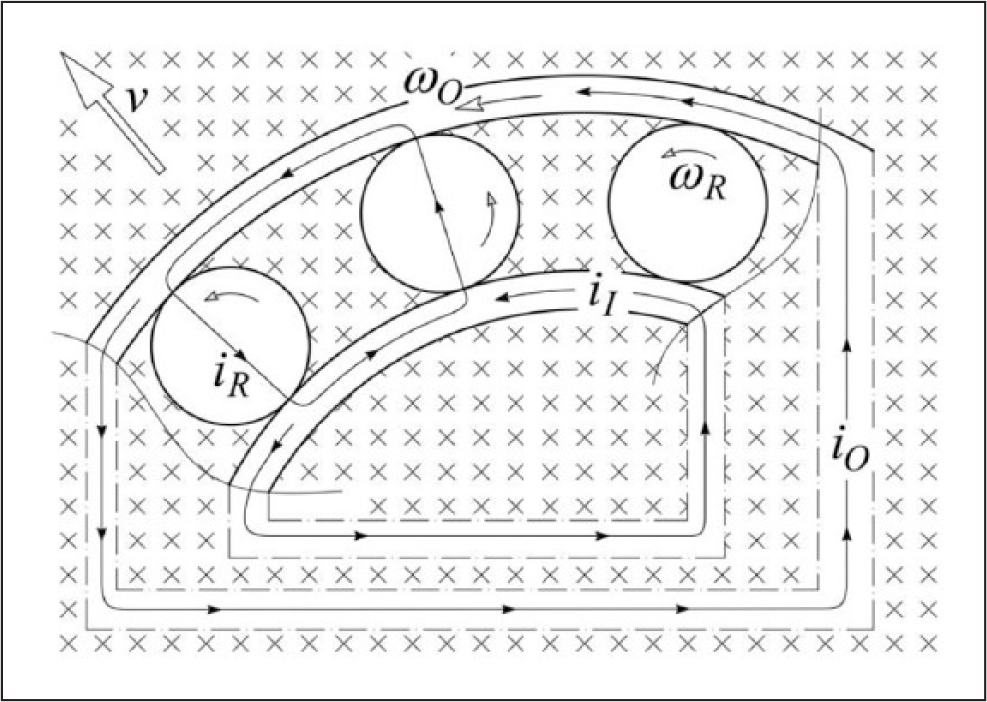
Schematic representation of the induced currents.
For this reason, some new tests have been carried out by letting currents flow through the sliding contact. In the new set of experiments, the applied load has been reduced with respect to the previous tests because we chose to lose a certain degree of acceleration of the test time in order to gain more similarity between the test stand and real system contacts. This is believed to be helpful to make the effects of current more evident with respect to the previous tests. Moreover, current flow in tribosystems has not received, up to now, the same attention in literature as the other standard tribosystems. As in the previous tests, Hertz formulae have been used to adjust the acceleration degree of the test due to pressure, because we had to take into account the spherical pin radius of the test stand and the real roller principal radii.
Results
Figure 2 shows a macroimage of the wear track due to the application of a 3 Hz alternate 8 N load for 2½ h, with 2 A current flowing through the contact. Wear (horizontal) is clearly visible on the surface across the grinding texture (vertical) although there are some irregularities in the middle of the track. In another experiment with the same test parameters, the current has been doubled (up to 4 A) and an interesting result was found, as illustrated in Figure 3. The inner irregularities now become an internal zone with virtually no wear. The latter seems concentrated on the external side of the track.

Macroimage of the test plate at 2 A with 8 N load and 3 Hz alternative cycling, after 2½ h (left-hand side).
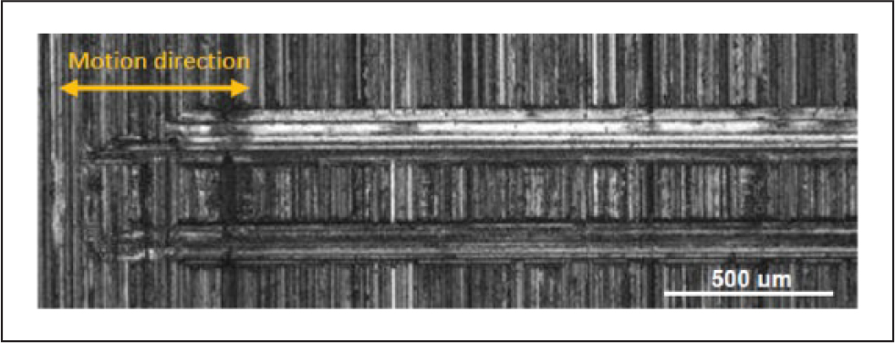
Macroimage of the test plate at 4 A with 8 N load and 3 Hz alternative cycling, after 2½ h (right-hand side).
For the sake of completeness, it is convenient to compare Figures 2 and 3 to Figure 4, which reports the SEM image of the wear track for the test without current flow at the same conditions (8 N load and 3 Hz alternative cycling). It is possible to note easily that only little wear scars are visible (in this image the direction of motion is vertically oriented). Scars are probably due to ordinary abrasive or abrasive/third-body particles or oxides.
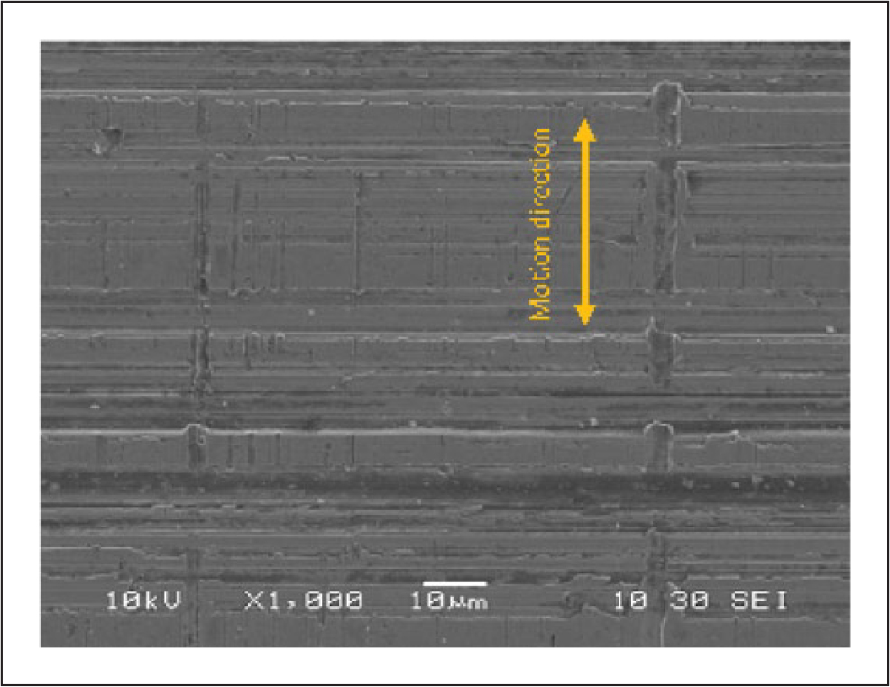
Macroimage of the test plate with 8 N load and 3 Hz alternative cycling, after 2½ h (right-hand side), with no current flow.
Discussion
It is not easy to interpret the results depicted in Figure 3 and so a deeper analysis has been conducted. A SEM-EDS characterization has been carried out. First, a transversal cross section of the sample has been obtained, after a metallographic preparation. Then, the EDS analysis has been carried out on three selected points of the cross section, as shown in Figure 5. Spectrum 3 refers to a point in the bulk, while Spectrum 5 to another point close to the surface of the analyzed cross section. Finally, Spectrum 4 has been obtained on a zone corresponding to a worn particle.
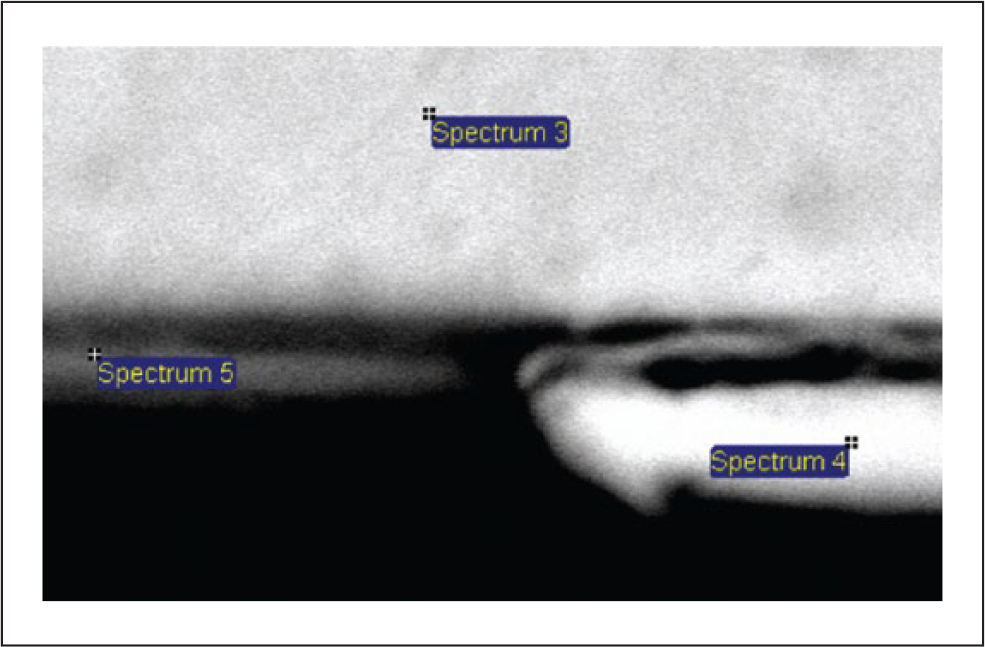
Area of application of EDS analysis (6 μm × 4 μm).
The EDS results are reported in Table 1. The area close to the Twin Tracks revealed a higher amount of oxygen and less chromium, compared with the bulk zone.
Results of EDS analysis in three zones near the border of the worn trace: bulk (3), worn particle (4), and close to the surface (5).

After all these activities, it is still difficult to give a reliable interpretation of the observed phenomenon, in a completely satisfying way. One possible interpretation could be based on the hypothesis that the combined action of current in the presence of oxygen develops severe wear, while the internal area, which is not exposed to the air during the ball alternate motion, remains protected and practically unloaded. However, it is still difficult to explain this behavior, while the presence of the twin track has been confirmed only in the presence of certain values of the current flow. Hence, more experimental tests are needed to understand how any single quantity affects the tribosystem.
Footnotes
Declaration of conflicting interests
The authors declared no potential conflicts of interest with respect to the research, authorship, and/or publication of this article.
Funding
The research leading to these results has received funding from the European Unions Research Fund for Coal and Steel (RFCS) research program under grant agreement no. RFSR-CT-20014-00018.