
Abstract
A prescribed-wake vortex model for evaluating the aerodynamic loads on offshore floating turbines has been developed. As an extension to the existing UMass analysis tool, WInDS, the developed model uses prescribed empirical wake node velocity functions to model aerodynamic loading. This model is applicable to both dynamic flow conditions and dynamic rotational and translational platform motions of floating offshore turbines. With this model, motion-induced wake perturbations can be considered, and their effect on induction can be modeled, which is useful for floating offshore wind turbine design. The prescribed-wake WInDS model is shown to increase computational efficiency drastically in all presented cases and maintain comparable accuracy to the free wake model. Results of prescribed-wake model simulations are presented and compared to results obtained from the free wake model to confirm model validity.
Introduction
Offshore wind turbines offer higher power production than onshore wind turbines due to their proximity to stronger, steadier coastal wind. Even small rises in local average wind velocity increase power output of turbines significantly. In many locations, however, the available shallow water locations for offshore wind development with fixed-bottom structures are limited, and therefore, floating support structures are necessary to access deepwater sites. Floating offshore wind turbines (FOWTs) have been at the demonstration phase for nearly a decade and are just beginning to become a commercial technology. Because the floating support structure has six additional degrees of freedom compared with a fixed-bottom structure, the rotor of an FOWT experiences larger structural motions and thus more complex aerodynamics due to unsteady and non-axial flow fields. To improve the understanding of FOWT behavior and design, a better understanding of the aerodynamics and performance is required.
Free wake vortex models (FVMs) are used widely to simulate the aerodynamic performance and loading of wind turbines (Keith, 1986; Shen, 2002; Zervos et al., 1988). FVMs are more accurate in calculating aerodynamic loading than other less physical models, such as the blade element momentum theory model (Madsen et al., 2010; Sørensen and Mikkelsen, 2001). Furthermore, the FVM is less computationally expensive than more intensive aerodynamic models, such as computational fluid dynamics (CFD) models (Sanderse et al., 2011). The efficiency and accuracy of the FVM makes it an ideal choice when modeling the aerodynamic loading of FOWTs. Sebastian and Lackner developed a lifting-line theory–based FVM code, WInDS, for the purpose of modeling FOWTs aerodynamics (Sebastian, 2012; Sebastian and Lackner, 2012a, 2012b). The research presented in this article focuses on recent additions to WInDS. By prescribing a time-varying platform motion for the FOWT, WInDS utilizes the FVM to calculate the unsteady aerodynamics experienced by FOWTs. This allows modeling of rotor-wake interactions caused by platform motion and their subsequent effect on induction and aerodynamic loading. However, for longer simulation times, the computational time of the FVM WInDS code increases by the power of n2 due to mutual induction in the Biot–Savart velocity calculations in the wake. This rapid growth in computational time motivates additions to the model that can reduce run time while preserving the physical accuracy of the unsteady aerodynamic calculations.
The use of prescribed-wake vortex models (PVMs) offers an efficient solution for reducing the run time of traditional FVMs. However, PVMs typically are applicable only to steady cases. Consequently, a PVM has been implemented into WInDS that is modified to incorporate the time-varying aerodynamic performance of the rotor into the wake advection model. The dynamic PVM implemented in WInDS uses wake velocity prescription functions in conjunction with a Forward Euler numerical integration scheme to progress the wake nodes forward in time. By prescribing the velocity of the trailing vortex nodes based on empirical equations derived by Coton et al., Biot–Savart mutual induction wake velocity calculations can be bypassed completely (Currin et al., 2008). This reduces simulation run time considerably. While PVMs have been applied to both horizontal-axis wind turbines (HAWTs) and vertical-axis wind turbines, research into the application of PVMs for FOWTs is lacking (Coton et al., 1994; Robison et al., 1995). This study investigates the implementation of a dynamic PVM in WInDS for the purpose of reducing computational time, while still accurately modeling unsteady aerodynamic rotor and wake behavior.
The following sections describe the wake velocity prescription functions and their role in WInDS, as well as the coordinate transformations used to expand the PVM to account for rotational motions of FOWTs. The NREL 5-MW rotor with the OC3/Hywind spar-buoy floating platform is simulated to test the performance of the model as it undergoes platform surge, yaw, and pitch. Then, results from the simulations of WInDS PVM and WInDS FVM are compared with each other. Various aerodynamic performance variables as well as wake node coordinates and angle of attack are compared between the models to test for validity of the WInDS PVM. Finally, the computational time of the simulations for both models is compared. The introduction of the WInDS PVM is shown to produce comparable results to those of the FVM but drastically reduced simulation run time.
The equations assume constant acceleration in the wake sections and continuity of flow. They have been tested within WInDS for their applicability to axial flow steady cases and cases including translational and rotational platform motion. For reference, the rotational degrees of freedom and coordinate system used for the WInDS PVM are shown in Figure 1.
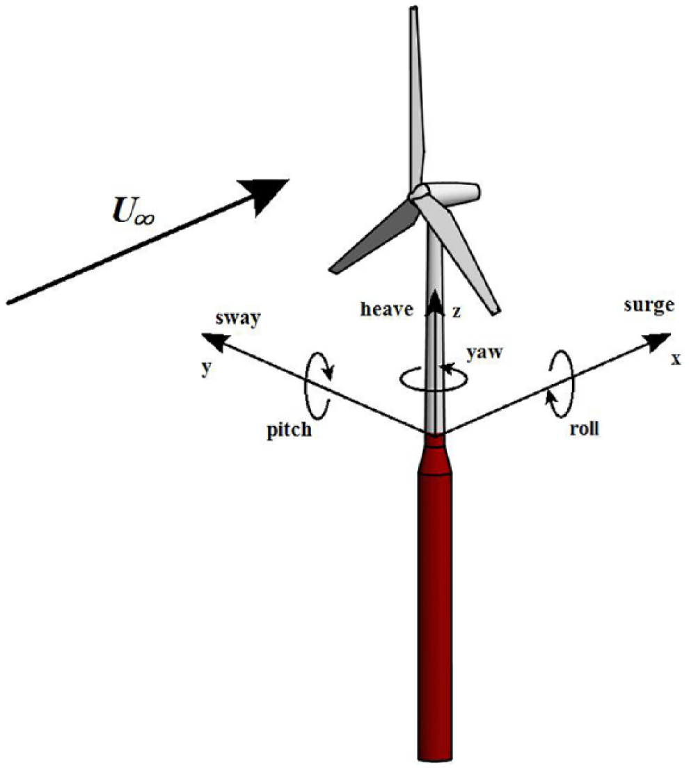
Degrees of freedom in the WInDS PVM model.
Implementation of the prescribed-wake model in WInDS
Traditional FVMs model trailing and shed vortex filaments in the wake. These vortices advect in time at the local velocity in the domain. This local velocity is influenced both by the freestream velocity and by mutual induction from the other vortex filaments, calculated via the Biot–Savart equation. The primary computational benefit of the PVM lies in its ability to bypass these Biot–Savart mutual induction velocity calculations, which are the main contribution to the computational cost of the FVM. While PVMs still use Biot–Savart calculations to determine the induction at the blade caused by all wake nodes, they use prescribed velocity functions to define the induced velocity of the wake nodes as the wake evolves in time. These prescription velocity functions thus replace mutual induction velocity calculations completely within WInDS.
The WInDS PVM is implemented with the same structure as the FVM except in how the model determines the local velocity at all wake nodes for the wake evolution. In the WInDS PVM, a Forward Euler numerical integration scheme is used to advect the wake in time, and the velocity used to advect the wake is directly calculated through the prescribed-wake equations. In contrast, in the WInDS FVM, this same velocity is calculated through Biot–Savart mutual induction calculations. The replacement of free wake model velocity calculations with the prescribed functions produces a substantial increase in computational efficiency.
The trailing node wake velocity prescription functions utilized in this research were developed empirically by other researchers for steady-flow cases but were then extended to yawed flow and found to be valid (Currin et al., 2008). The equations that follow in this section form the basis of the WInDS PVM and can model axial flow cases and cases that include translational platform motion. These equations are used in tandem with a rotational model to simulate cases in which the turbine is undergoing rotational platform motion.
The wake node velocity functions depend on axial induction at the time the node is released from the blade, a, the freestream velocity V1, and a wake velocity deficit function, F (Currin et al., 2008)
where r is the blade radius at the node station and R is the total blade radius. The value of axial induction, a, at the time of node release from the blade is initialized within the PVM model using blade element momentum theory for the second and third time-steps due to the time loop structure of WInDS. For all other time-steps, this axial induction is calculated directly based on the local relative velocity at each blade node.
The wake is divided into three sections according to wake age, and the velocity is prescribed accordingly. Each wake age time division is divided relative to the time in which the wake reaches its final velocity, and is measured in seconds. The velocity of trailing nodes in the X-direction is prescribed as follows (Currin et al., 2008)
where dt represents the change in time between the current time-step and the previous.
The trailing node velocities in the Y and Z coordinate directions depend on a near-wake velocity deficit function, Va, and axial induction at the time the nodes are released from the blade. The near-wake velocity deficit function is defined as follows (Currin et al., 2008)
A linear wake expansion is assumed and the far-wake is assumed to begin at 2 rotor diameters behind the turbine. Figure 2 depicts the linear wake expansion for the model and the corresponding variables used in the following equations. The freestream velocity is assumed to reach a value of U1(1–a) at the rotor plane and a value of U1(1–2a) at the beginning of the far-wake, which is modeled at 2 rotor diameters behind the rotor.
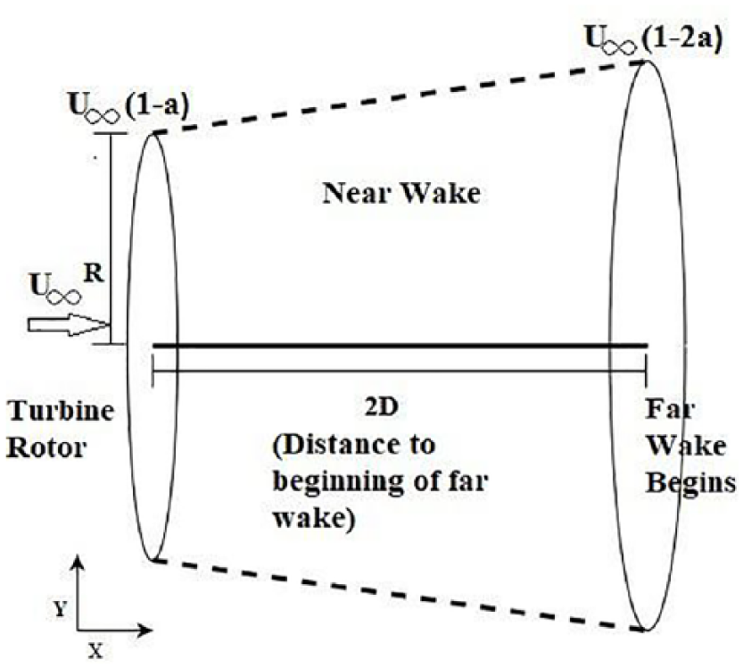
Linear wake expansion diagram with corresponding variables.
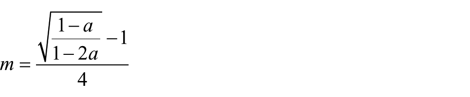
The Y and Z prescription velocities for the trailing vortex nodes also depend on the slope of the wake, m, which is calculated using the blade radius and axial induction
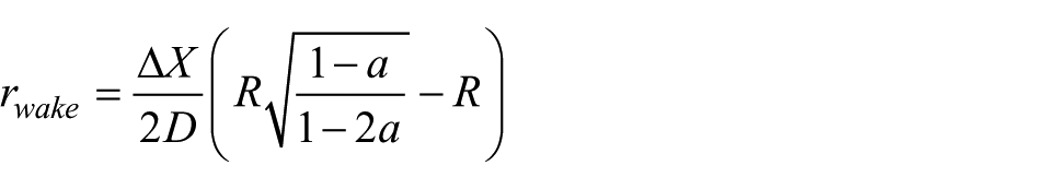
The Y and Z velocities also depend on the total wake radius for the time-step, rwake. rwake is modeled using the rotor diameter, axial induction, and change in trailing node X position as follows
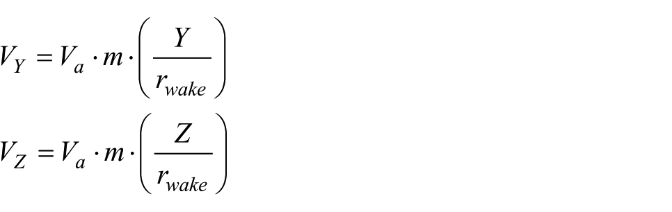
VY and VZ are modeled as follows using the Y and Z coordinate locations, wake slope, wake radius, and the near-wake velocity deficit function
The previous equations describe the implementation of the PVM within WInDS for steady cases, and their validity is confirmed for the case of axial flow in the following sections of this article. The previous equations, when incorporated into WInDS, are also capable of modeling dynamic wake behavior due to translational platform motions of the turbine in two ways: (1) the relative velocity at the blade nodes due to the platform motion is directly incorporated into the induction calculations, and (2) the position at which the vortex filaments are released into the wake depends upon the blade position, which depends on the platform motion. Thus, the axial induction is dynamic, and the subsequent wake advection incorporates these dynamic effects. These results are verified in the following sections. The next section describes the extension of the steady-case model to a model that can account for rotational platform motions of the turbine.
WInDS prescribed-wake model for rotational platform motion
While the equations in the previous section were implemented into WInDS for cases of translational platform motion and axial flow, additional modeling was required to expand the WInDS PVM to account for rotational platform motion. The application of Euler’s rotation theorem to the wake velocity components is used to model the additional wake perturbation caused by platform movements. This involves treating each wake node experiencing rotation as a rigid body rotating about a fixed axis. The rotational axis for each wake node corresponds to the axis about which the wind turbine is rotating, for each case of rotational platform motion.
After the PVM calculates the velocity at the wake nodes via the equations described in the previous section, it then transforms these velocity components using an Euler rotation matrix. The transformation of the wake velocity components is relative to the rotational motion of the turbine platform, which is prescribed for each time-step and is consequently used to transform the wake node velocity for each time-step. For example, as the turbine is rotated at an angle about its Z axis for a given time-step, the wake velocity coordinates of each node are transformed about their respective Z axis by an Euler transformation matrix of E, denoted below. Since the wake advection is calculated through the Forward Euler numerical integration of the wake velocity, it is not necessary to transform the wake domain itself to account for rotational platform motion.
Rotation angles are identified with standard Euler angle notation. The platform pitch angle and its Euler rotation matrix are denoted as Eϕ and E, respectively. Similarly, the platform yaw angle and its Euler rotation matrix are denoted as E∅ and E, respectively. The application of the Euler transformation theorem to the velocity components is shown below
The equations discussed in the previous sections describe the implementation and structure of the WInDS PVM. The next section presents simulation data from the WInDS PVM and compare it to simulation data from the WInDS FVM.
Results and discussion
In order to verify the WInDS PVM, four simulations (Cases 1–4) were run in the WInDS PVM and the WInDS FVM for 100 s each. The time-step frequency was set to 10 Hz for each simulation. Although WInDS is capable of modeling the effects of dynamic stall and tower shadow on turbine performance, these were neglected in favor of testing the basic functionality of the PVM. The long simulation length was chosen in order to fully observe the effect of transient flow conditions and platform motion on the wake evolution. The freestream velocity was kept at 9 m/s for each simulation, with a tip-speed ratio of 7. Case 1 was run without platform motion, that is, a steady case. The simulations including platform motion are cases 2, 3, and 4, which simulate platform surge, pitch, and yaw, respectively. For all cases of platform motion, the simulations were run using prescribed platform motion that are outputs from Fatigue Aerodynamics, Structures, and Turbulence (FAST) simulations for the NREL (aerolastic simulator) 5-MW rotor and the OC3/Hywind spar-buoy floating platform.
Case 1: steady case
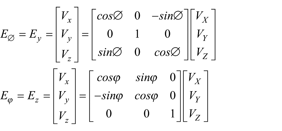
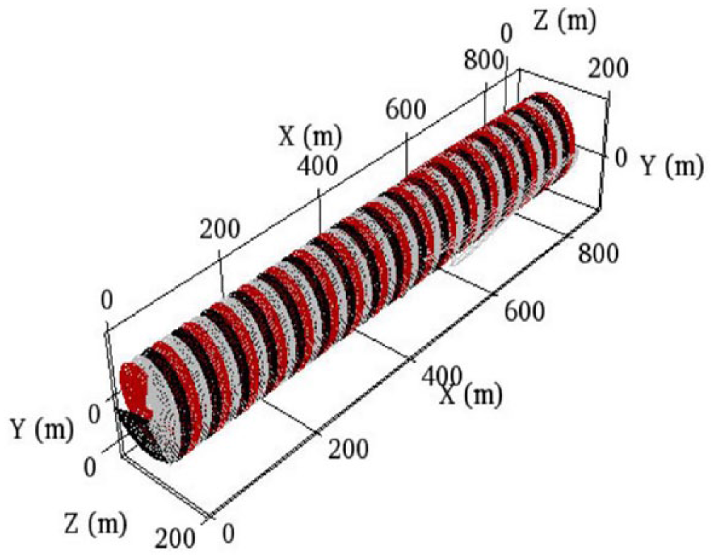
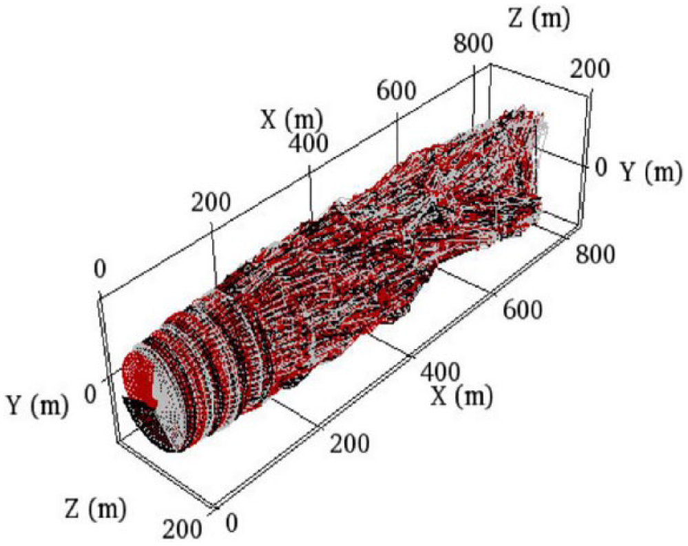
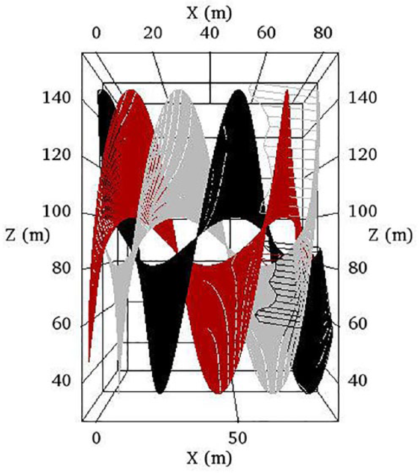
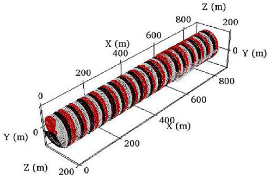
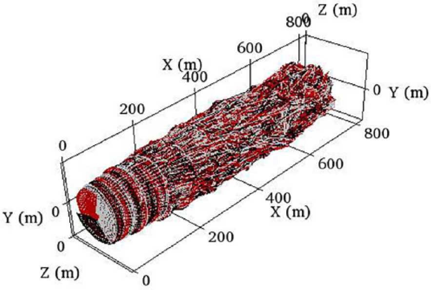
Figures 3 and 4 compare the wake produced by the FVM and PVM case 1 simulations. In the free wake case, tip roll-up can be observed, which is more physically realistic than the lack of tip roll-up in the prescribed case. The far-wake of the FVM case eventually breaks down and becomes unstable due to node interaction and mutual induction, while the far-wake of the prescribed case does not. This is evidence of the physical difference between the PVM and the FVM; mutual induction velocity effects are fully accounted for in the FVM while they are prescribed in the FVM. The similarity in the near-wake of the FVM and PVM simulations is evident. Since no platform motion has been introduced, the wake experiences no visible axial compression or expansion, which can be observed in the symmetry of the wake and uniform distance between each rotation of the nodes as they advect downstream. The wake of the FVM simulation is slightly more compact than that of the FVM due to the effects of mutual induction. Wake width and height are comparable in both simulations.
Visual of the wake produced by WInDS PVM—steady case.
Visual of the wake produced by the FVM—steady case.
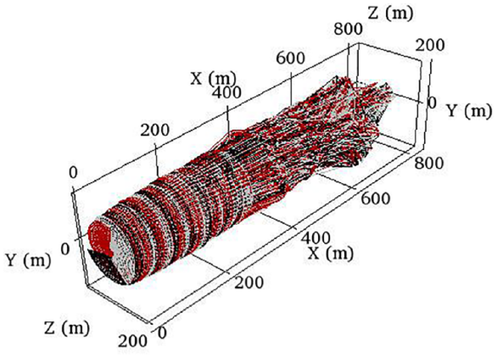
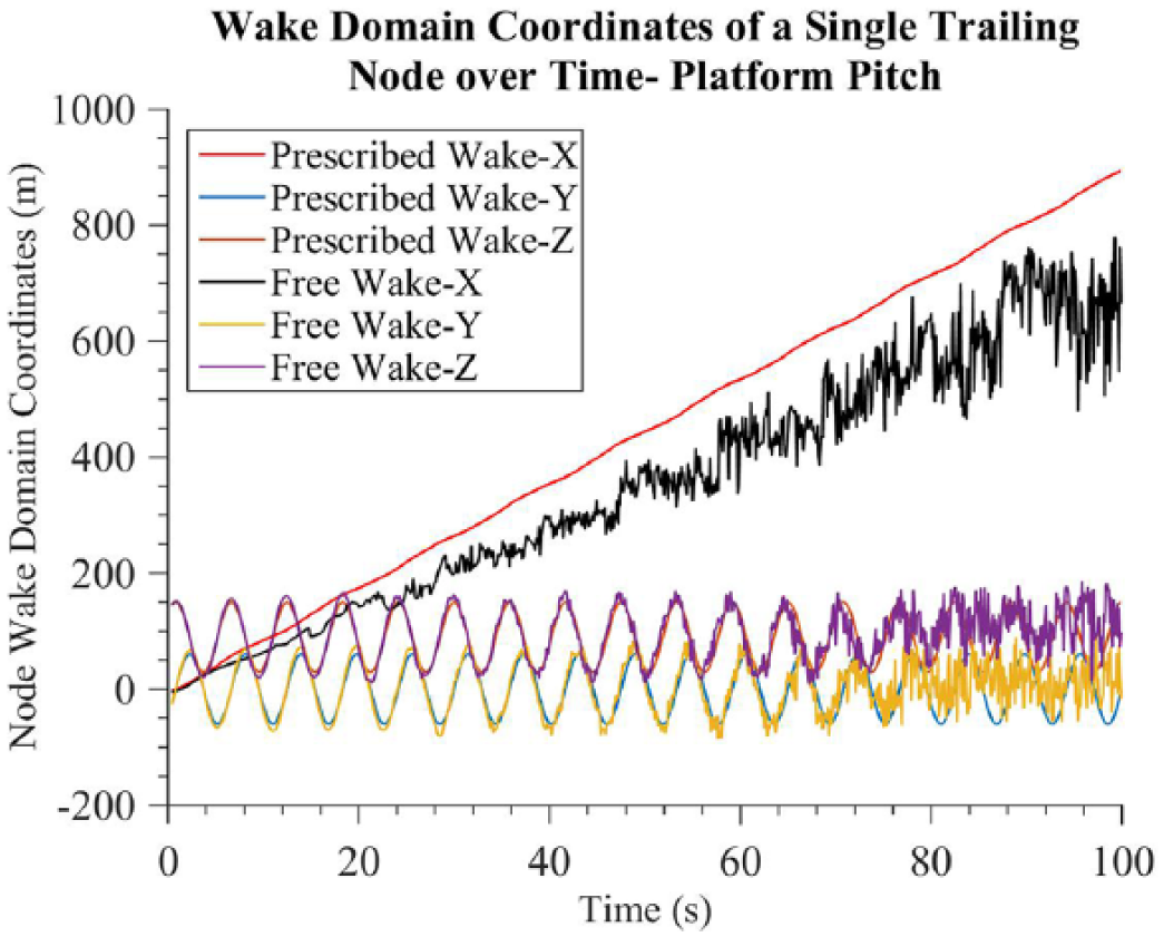
Figure 5 shows the comparison of the position of a single trailing node in the wake over time for case 1. The Y and Z wake coordinates in both simulations compare well as the node advects downstream. The instability of the far-wake of the FVM for the later time-steps is clear. Earlier in the simulation, the Y and Z coordinates of the node for the FVM and PVM are very comparable, while the X coordinates differ somewhat between the two models. In the PVM, the wake node advects in the X-direction more rapidly than the FVM case. The cause of this discrepancy is still under investigation and could likely be improved through tuning of the empirical constants in the PVM, which were developed for a different wind turbine model. Figures 6 to 8 show several performance variables: angle of attack, rotor power, and rotor thrust for the axial flow case. As time increases, the performance variables are observed to approach steady state. The difference in the steady-state performance values is likely due to the difference in the wake advection velocity and thus the wake node position, as shown in Figure 5. The wake induction on the rotor depends on the position of the wake nodes in both models, so differences between the models cause differences in the rotor induction and thus the angle of attack, power, and thrust. Again, tuning of the empirical constants in the PVM may result in more accurate wake advection and thus more similar performance variables.
Wake domain coordinates of a single trailing node over time—steady case.
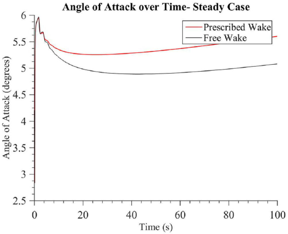
Angle of attack for a single blade over time—steady case.
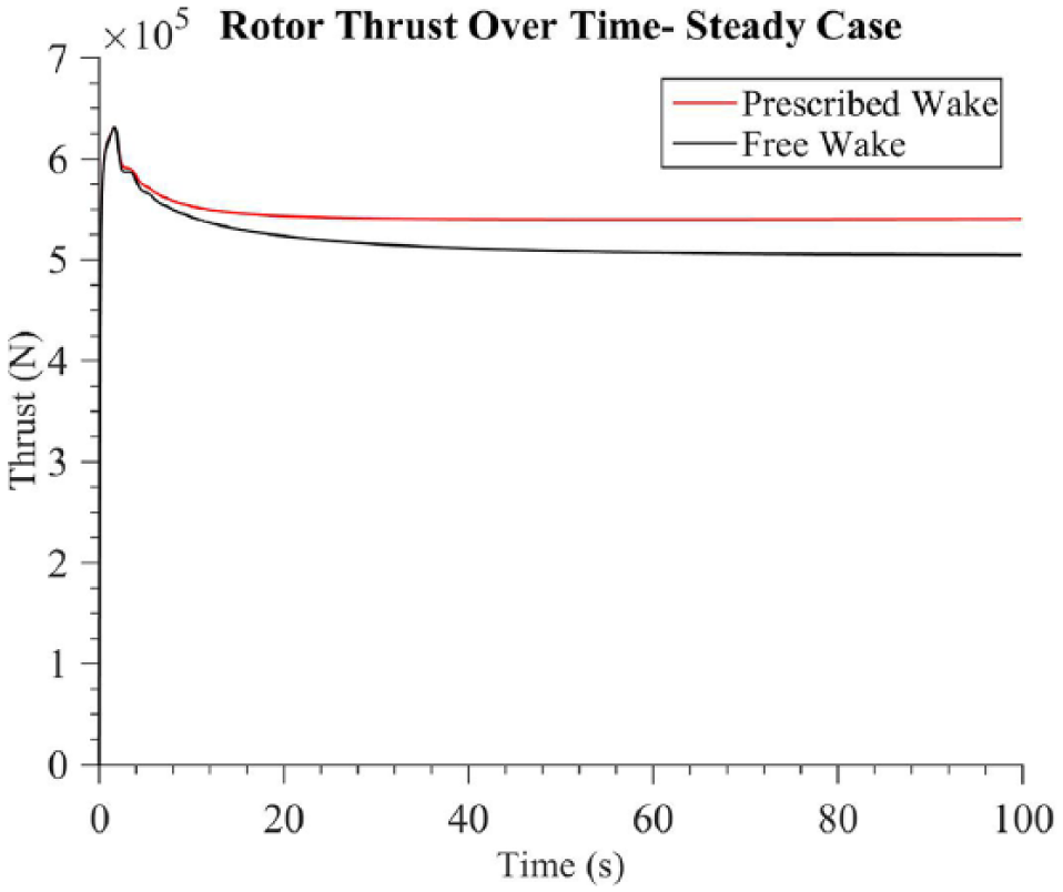
Rotor thrust over time—steady case.
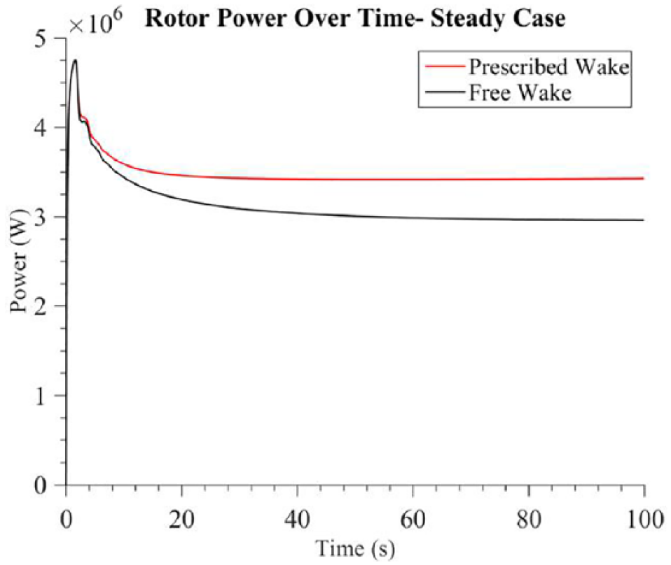
Rotor power over time—steady case.
Case 2: platform surge
Case 2 simulated the OC3/Hywind spar-buoy platform and NREL 5-MW rotor undergoing prescribed sinusoidal platform surge with an amplitude of 1 m at a frequency of 0.1 Hz.
Figures 9 and 10 show the wakes produced by both the FVM and the PVM. In both the PVM and FVM, axial compression and expansion of the wake due to platform motion are observed. However, because the value of surge amplitude in this case is relatively small (1m) compared to the turbine wake and dimensions, it is difficult to observe the axial effects of platform surge in the wake visualization of the PVM. In order to display axial compression and expansion in the PVM due to surge, Case 2a presents a shorter simulation run at a higher time-step frequency and with a higher surge amplitude of 3 m. Axial compression and expansion is visible in the wake evolution, and results from Case 2a are discussed further in this section.

Visual of the wake produced by WInDS PVM—platform surge.
Visual of the wake produced by the FVM—platform surge.
The additional unsteady forcing in the free wake model due to platform surge causes its far-wake to become unstable sooner than in the previous case of no platform motion. The prescribed-wake model again experiences no instability in its far-wake. The wake width and height of the PVM wake are again comparable to that of the FVM wake.
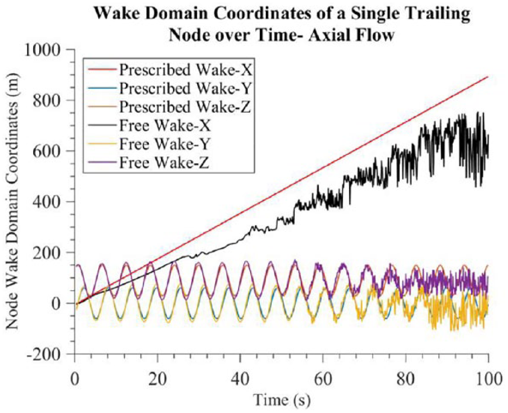
Figure 11 compares the position of a single trailing node in the wake over time for case 2. The earlier occurrence of wake instability, as seen in the rendering of the FVM wake above, is visible in the nodal position for the FVM results. Compared to the steady case, instability begins at approximately 20 s of simulation time, instead of 50 s in the steady case. The Y and Z wake coordinates in the FVM and PVM simulations compare well as the node advects downstream. On again, in the PVM, the wake node advects in the X-direction more rapidly than the FVM case, likely for the same reason as the steady case. Despite the difficulty to visualize axial expansion and compression in Figure 10, the impact of surge motion can be seen in the slight sinusoidal variation of X position in the PVM in Figure 11. This sinusoidal variation in the X-node position when compared to the linear X-node position of the steady case verifies the effect of platform surge on the PVM.
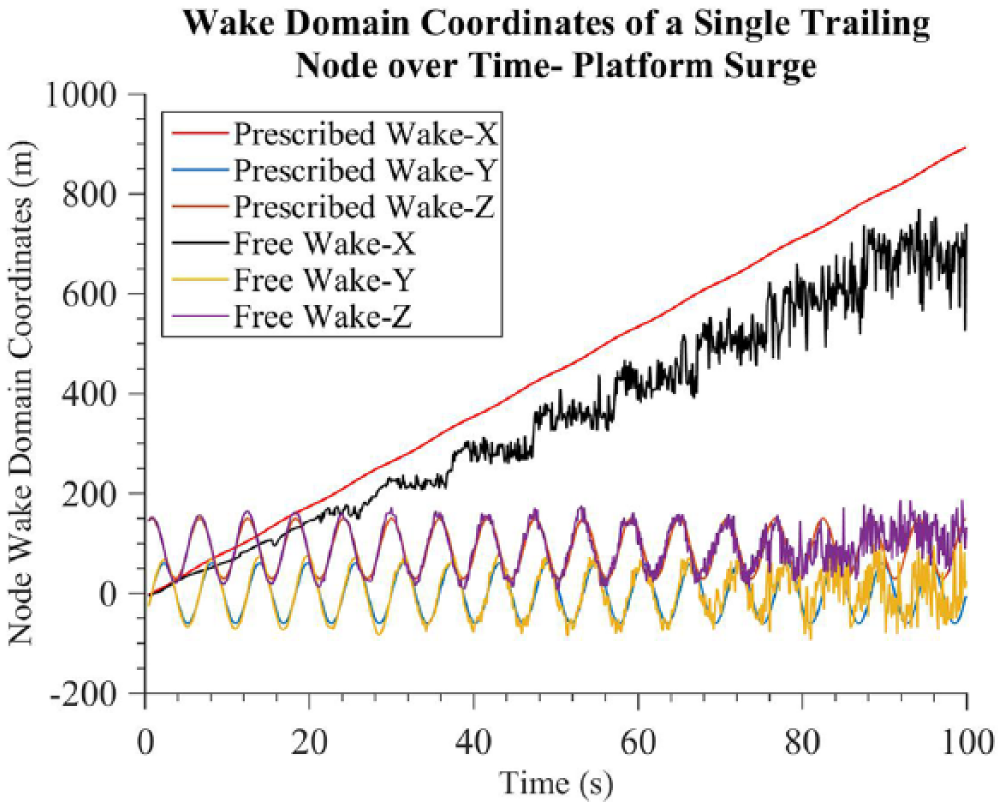
Wake domain coordinates of a single trailing node over time—platform surge.
Figures 12 to 14 show performance variables of angle of attack, rotor power, and rotor thrust for the surge case. As in the steady case, there is a mean offset between the FVM and PVM results, likely due to the difference in the downstream wake advection speed, as explained previously. Nonetheless, the results match well when comparing the impact of the unsteady platform surge motion, which introduces a sinusoidal signal on each of the performance variables. The amplitude, frequency, and phase of the variations match well between FVM and PVM, indicating that PVM is accurately capturing the unsteady aerodynamic effects in the model.
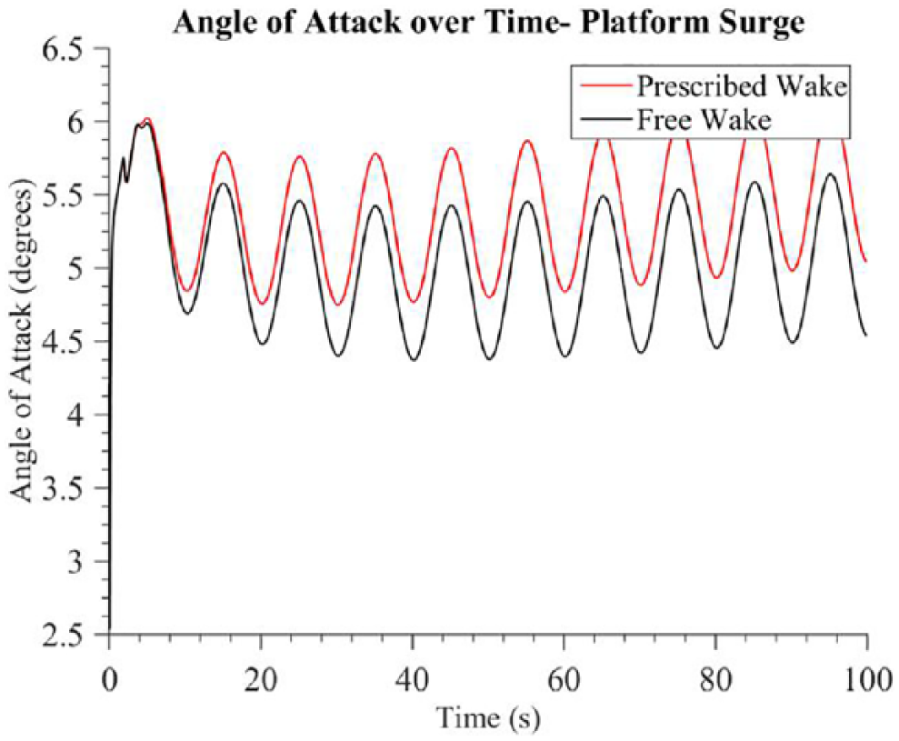
Angle of attack for a single blade over time—platform surge.
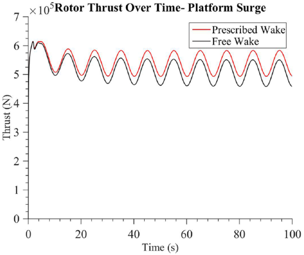
Rotor thrust over time—platform surge.
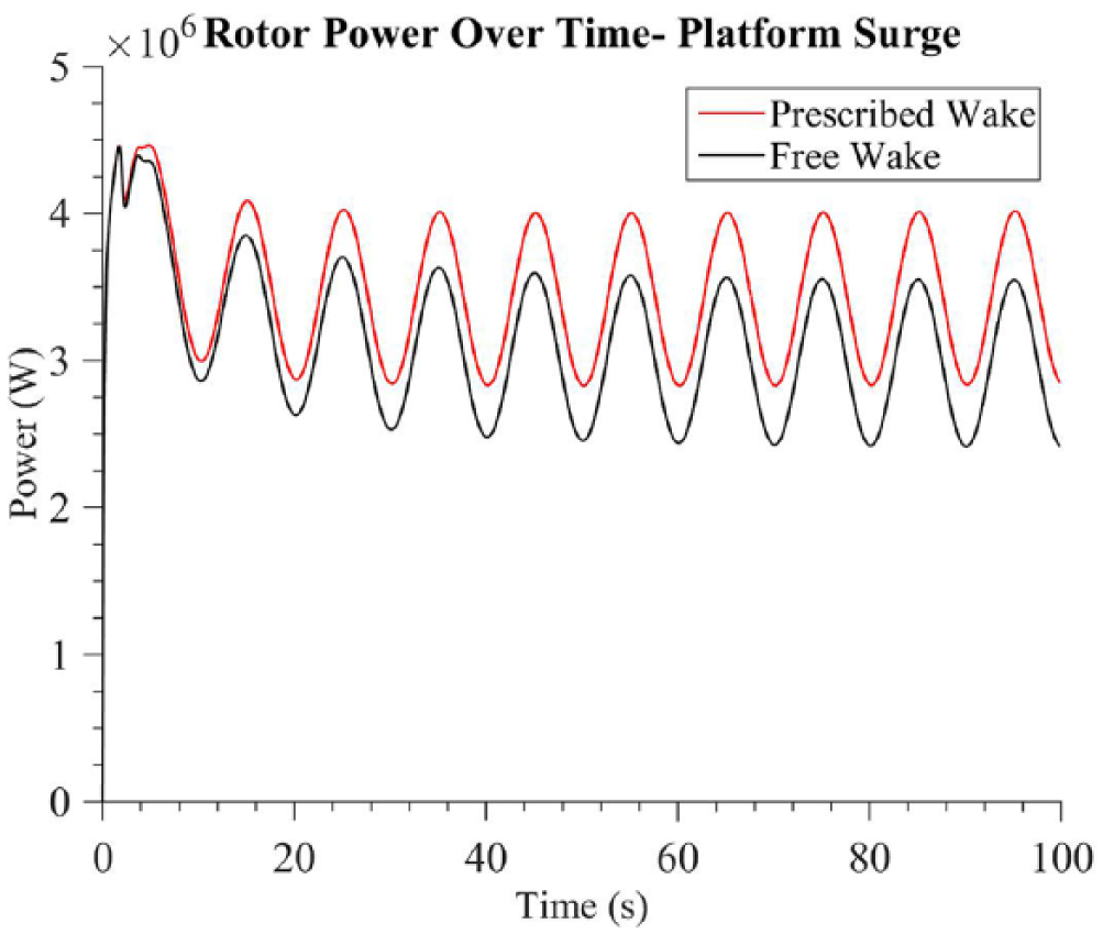
Rotor power over time—platform surge.
Case 2a: platform surge, increased surge value
An additional case was run to verify that wake expands and compresses with the introduction of platform surge. The simulation parameters were the same as Case 2, except the simulation time was 10 s, and the time-step frequency was 30 Hz. The platform surge was prescribed with a sinusoidal amplitude of 3 m at a frequency of 0.1 Hz. As seen in Figure 15, platform surge creates noticeable axial compression and expansion in the wake of the PVM when the value of platform amplitude surge is large enough, verifying again that unsteady platform motion directly impacts the wake structure in the PVM code.
Visual of the wake produced by WInDS PVM—platform surge, 10 s, time-step frequency of 30 Hz.
Case 3: platform pitch
Case 3 simulated the OC3/Hywind spar-buoy and NREL 5-MW rotor undergoing prescribed sinusoidal platform pitch motion with an amplitude of 1° at a frequency of 0.1 Hz.
Figures 16 and 17 show the wake structures produced by the PVM and the FVM. Similarly to the behavior of the surge case, the FVM wake experiences instability earlier than in the steady case. Perturbations in the wake structure of the PVM can be observed by the compression and expansion in the wake. It is also possible to observe the angled release of nodes from the blade as the rotor pitches. The wake of the PVM again advects downstream more rapidly than that of the FVM. Figure 18 compares the position of a single trailing node in the wake over time for Case 3. The earlier occurrence of wake instability, as seen in the rendering of the FVM wake above, is visible in the nodal position for the FVM results. The Y and Z wake coordinates in the FVM and PVM simulations compare well as the node advects downstream. On again, in the PVM, the wake node advects in the X-direction more rapidly than the FVM case. The impact of pitch motion can be seen in the slight sinusoidal variation of the X position in the PVM.
Visual of the wake produced by WInDS PVM—platform pitch.
Visual of the wake produced by the FVM—platform pitch.
Wake domain coordinates of a single trailing node over time—platform pitch.
Figures 19 to 21 show the performance variables for the PVM and FVM when undergoing platform pitch. Again, there is a small mean offset between the FVM and PVM results, likely due to the difference in the downstream wake advection speed. Nonetheless, the results match well when comparing the impact of the unsteady platform pitch motion, which introduces a sinusoidal signal on each of the performance variables. The amplitude, frequency, and phase of the variations match well between FVM and PVM, indicating that PVM is accurately capturing the unsteady aerodynamic effects in the model, as well as the rotational transformation described in the methodology.
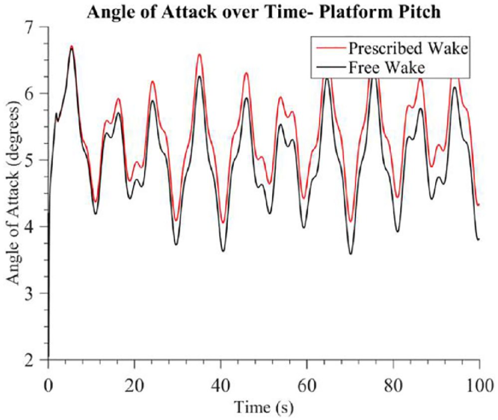
Angle of attack for a single blade over time—platform pitch.
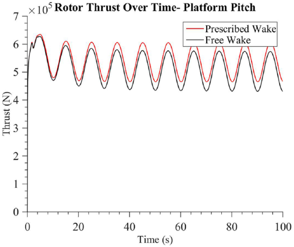
Rotor thrust over time—platform pitch.
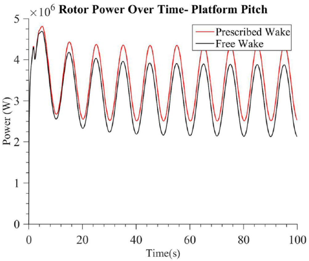
Rotor power over time—platform pitch.
Case 4: platform yaw
Case 4 was simulated by prescribing sinusoidal platform yaw motion with an amplitude of 5°at a frequency of 0.1 Hz. Figure 22 compares the position of a single trailing node in the wake over time for Case 4. Again, the Y and Z wake coordinates in the FVM and PVM simulations compare well, and in the PVM, the wake node advects in the X-direction more rapidly than the FVM case. The impact of yaw motion can be seen in the slight sinusoidal variation of the X position in the PVM.
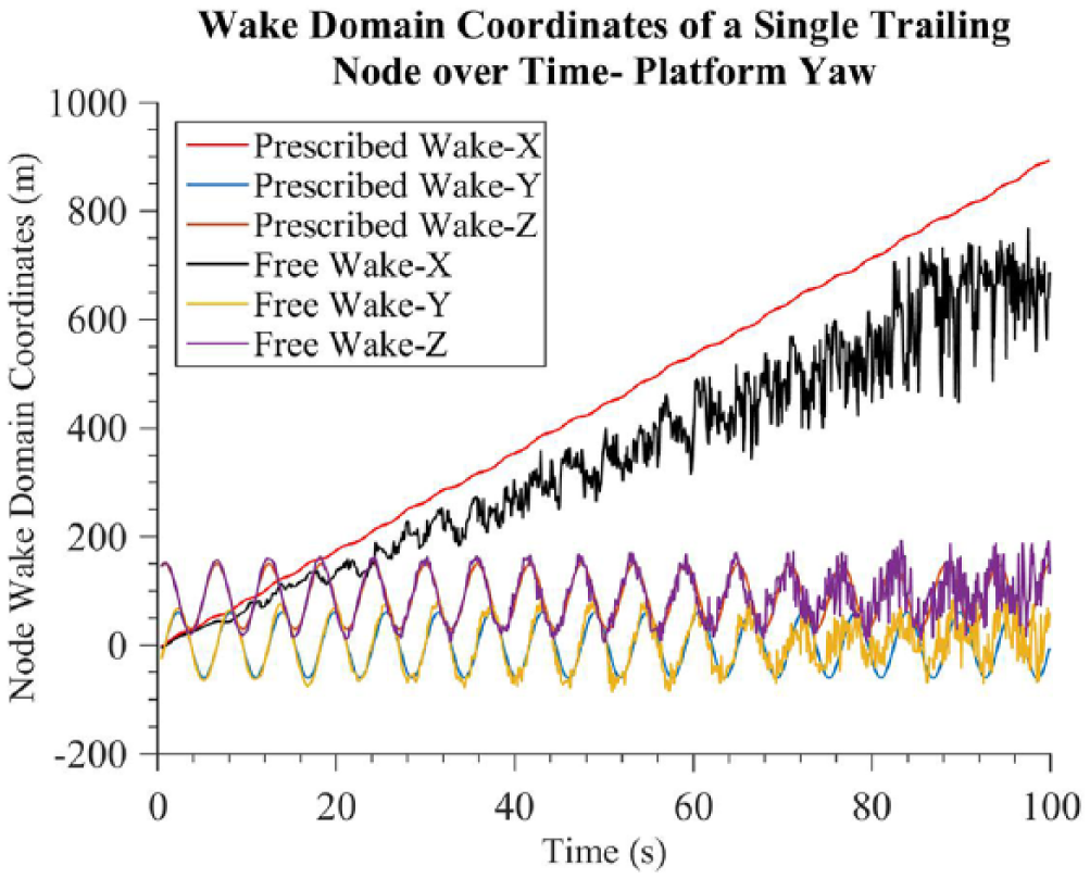
Wake domain coordinates of a single trailing node over time—platform yaw.
Figures 23 to 25 show the performance variables. Again, there is a mean offset between the FVM and PVM results, but the amplitude, frequency, and phase of the variations match well between FVM and PVM, indicating that PVM is accurately capturing the unsteady aerodynamic effects in the model, as well as the rotational transformation described in the methodology.
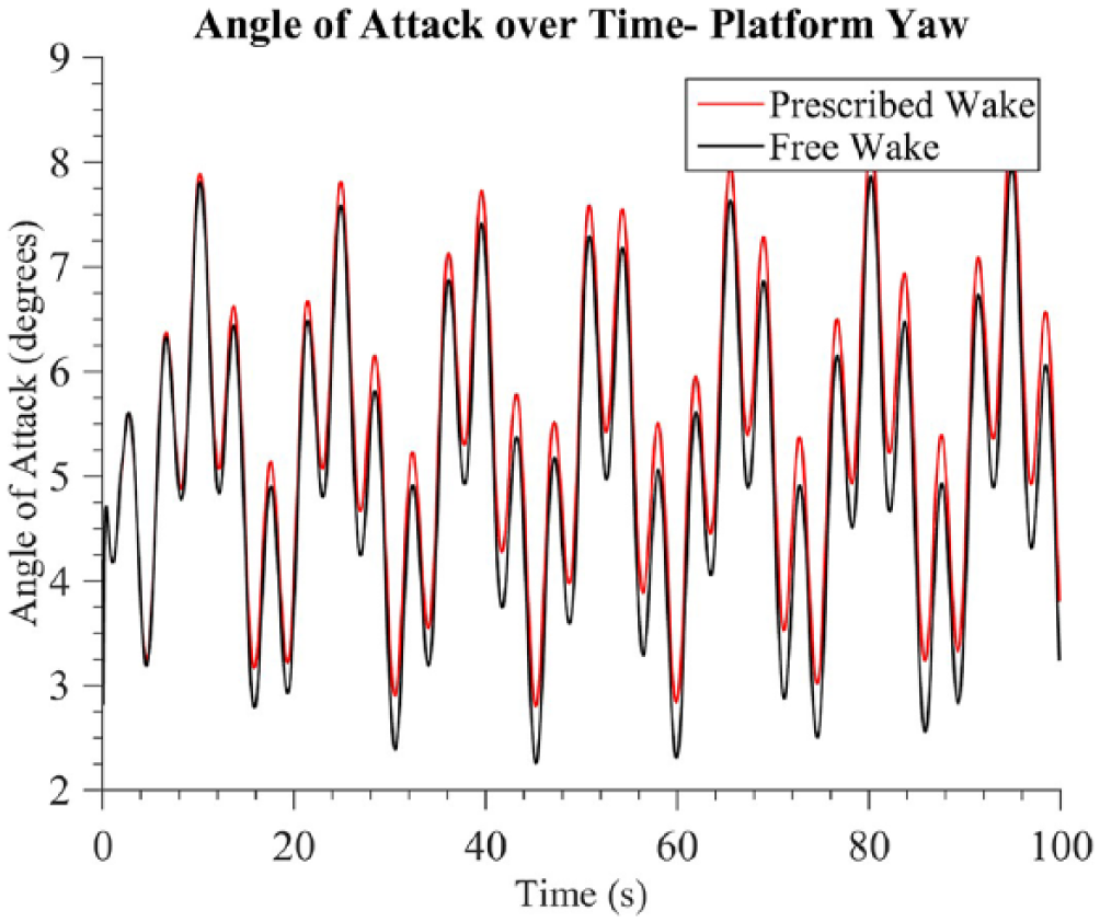
Angle of attack for a single blade over time—platform yaw.
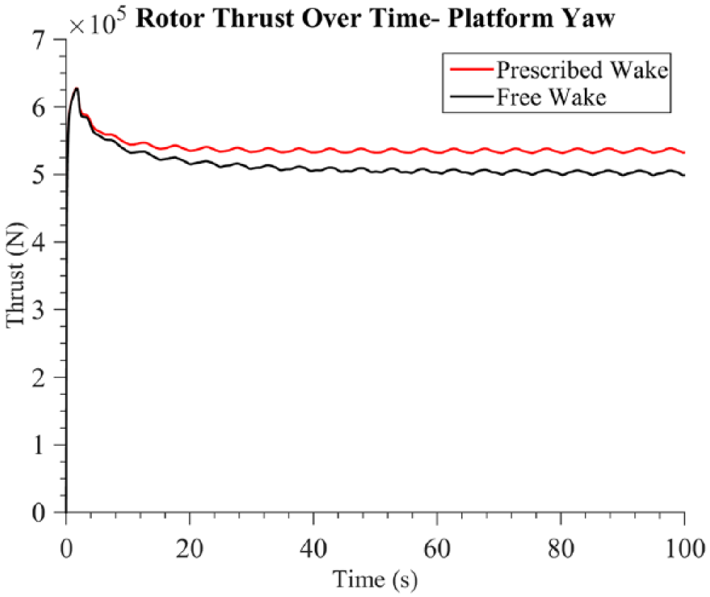
Rotor thrust over time—platform yaw.
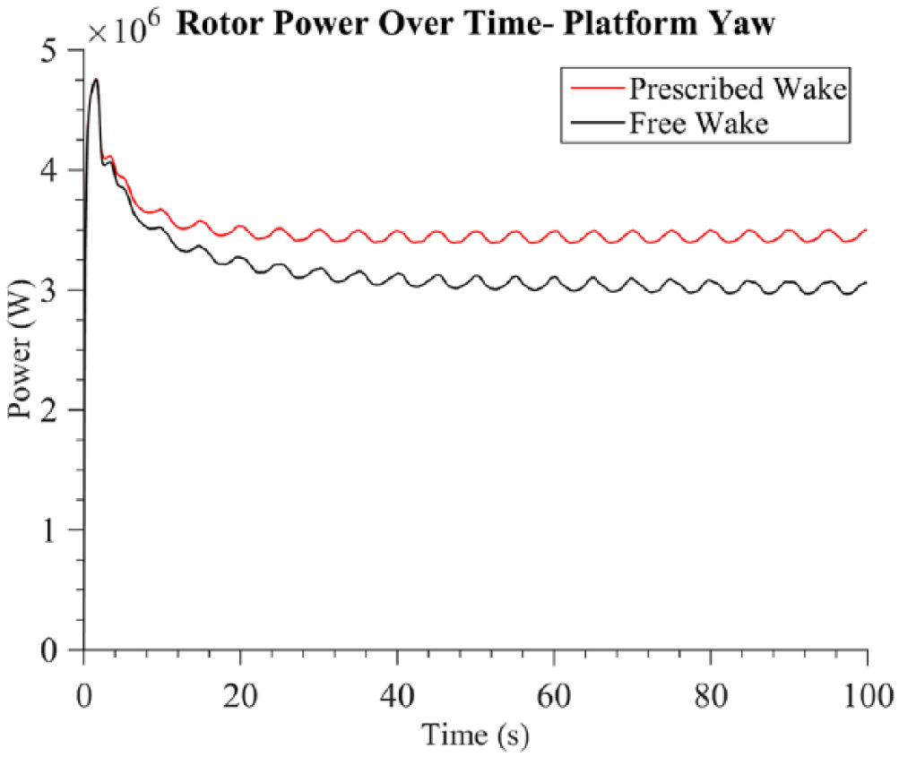
Rotor power over time—platform yaw.
Comparison of computational times between free and prescribed-wake models
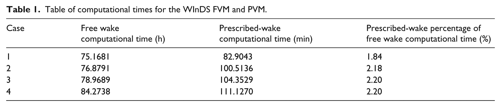
The previous section highlighted the simulated physical results of the PVM and FVM. The following table highlights the computational advantages of the implementation of the WInDS PVM. WInDS PVM is extremely computationally efficient when compared with the FVM simulations in all cases. The average simulation time of the PVM is around 2% of that of the FVM. Introducing platform motion to the PVM increases simulation time by 27% on average when compared with simulation time of the steady case (Table 1).
Table of computational times for the WInDS FVM and PVM.
Conclusion
A prescribed-wake model, modified to handle unsteady and rotationally varying rotor motion, was implemented into WInDS. The WInDS PVM was first tested for validity for a steady case with axial flow. The prescribed-wake model was then tested for its applicability to unsteady simulations including translational and rotational platform motion.
The results of the prescribed-wake model generally compare well with those of the free wake model, especially in terms of the Y and Z position of wake nodes, and the time-varying behavior of the performance variables. The main source of discrepancy is the wake advection velocity in the X-direction, which is larger for the PVM code, leading to a mean offset in the performance variables. Future work will investigate modifications to the empirical constants in the PVM that can lead to a better-matched downstream wake advection velocity.
Overall, the WInDS prescribed-wake model has proven to be fairly accurate for translational, rotational, and steady platform cases. It also yields a substantial decrease in computational time when compared to the free wake model. It provides a useful tool for analyzing the effect of unsteady platform motion on the aerodynamics of FOWTs.
Footnotes
Declaration of conflicting interests
The author(s) declared no potential conflicts of interest with respect to the research, authorship, and/or publication of this article.
Funding
This work is supported in part by the National Science Foundation under NSF award number (1460461). Any opinions, findings, conclusions, or recommendations expressed in this material are those of the authors and do not necessarily reflect those of the National Science Foundation.