
Abstract
In order to address the intermittency of offshore renewable energy sources, a novel form of compressed air energy storage integrated within a tension leg platform is proposed. The energy storage concept involves a hydro-pneumatic accumulator. The objective of this study was to investigate the variation in the physical and hydrodynamic characteristics of a hypothetical full-scale prototype of the proposed system. The design was developed so as to analyse the effect on said characteristics of the tension leg platform diameter and the inner diameter of the umbilical connecting the floating and seabed-mounted compressed air chambers. Results indicate that better hydrodynamic behaviour was observed for smaller diameter tension leg platforms, whereby the resulting motion became more restrained. Moreover, the dynamic characteristics were observed to indicate marginal improvement for increasing inner diameters of the pneumatic umbilical.
Keywords
Introduction
Generating power from the wind is one of the main alternatives to fossil fuels. To date, the vast majority of wind farms have been built onshore or in shallow water. However, stronger and steadier winds further offshore and vaster spatial availability have generated interest in floating support structures. In order to investigate the feasibility of such platforms, modelling and simulation are carried out. The National Renewable Energy Laboratory (NREL) in the United States developed a 5-MW baseline wind turbine (Jonkman et al., 2009) for the purpose of analysing floating wind turbine systems. A tension leg platform (TLP) for this turbine was designed by Matha (2009) and developed further by Bachynski and Moan (2012).
One of the main challenges of generating power from renewable sources is their intermittent nature, which, in many instances, results in the decoupling of the time of production from that of consumption. Hence, energy storage is of necessity. Compressed air energy storage (CAES) is one technology using compressed air to store energy and which is then heated and released through a turbine to generate power. Underwater-type CAES involves processes that make use of the hydrostatic pressure. The technology was first proposed by Seymour (1997) and has been developed further by Pimm et al. (2014) and Cheung et al. (2012) through the use of flexible balloon-like air accumulators.
An innovative underwater CAES system was proposed by Sant and Buhagiar (2016) where a near-isobaric compression process is accomplished using a liquid piston accumulator and exploiting the nonlinear relationship between pressure and volume during gas compression. Such a concept may be integrated into the geometry of a TLP, as illustrated in Figure 1. The conceptual system consists of a TLP anchored by means of a gravity foundation that also doubles as a liquid piston accumulator which is initially filled with air. During the energy storage part of the cycle, seawater is pumped into the seabed chamber compressing the air, and during the discharge cycle, the pressurised air expels the seawater through a hydraulic turbine to generate power. An additional volume of air is integrated with the floating component of the TLP. This serves to absorb pressure fluctuations and provide stabilising upthrust. The floating and seabed pressure vessels are connected via a pneumatic umbilical. The system has been patented (WO 2016/128962 A1) (Sant and Buhagiar, 2016).

The hypothetical full-scale prototype indicating the main components and their dimensions.
The scope of the work presented in this research was the hydrodynamic analysis of this conceptual system. The effect of varying the platform diameter and umbilical inner diameter on the time-response characteristics under regular wave conditions was investigated through a parametric analysis. This research work was accomplished using the hydrodynamic analysis tools included in the software package ANSYS® AQWA™.
Overview
The main parameters characterising the TLP design integrating the energy storage system are shown in Figure 1. The design involves a steel cylindrical pressurised air storage vessel of diameter
With regard to terminology, note that the rotor-nacelle assembly and tower are collectively referred to as the turbine while the vessel and fairleads constitute the platform (TLP). Together, the turbine and platform are referred to as the floater.
Both storage chambers would initially be filled with air at the same pressure. When fully charged, the anchor chamber would be pumped full of seawater, and thus the pressure in the platform vessel increases to a maximum pressure
In this analysis, the system was subjected to two metocean conditions: operation and extreme. Operation conditions represent a typical scenario with a rated wind speed,
In order to investigate the effect of variation in the TLP hull diameter
Design details
The details of the wind turbine are given in Table 1 together with the wind loads developed as identified in Figure 2. When operating at the rated wind speed, the rotor develops a thrust,
Properties and dimensions of the NREL wind turbine, gravity foundation (anchor) and mooring cables.

NREL: National Renewable Energy Laboratory; RNA: rotor-nacelle assembly; CoG: centre of gravity.
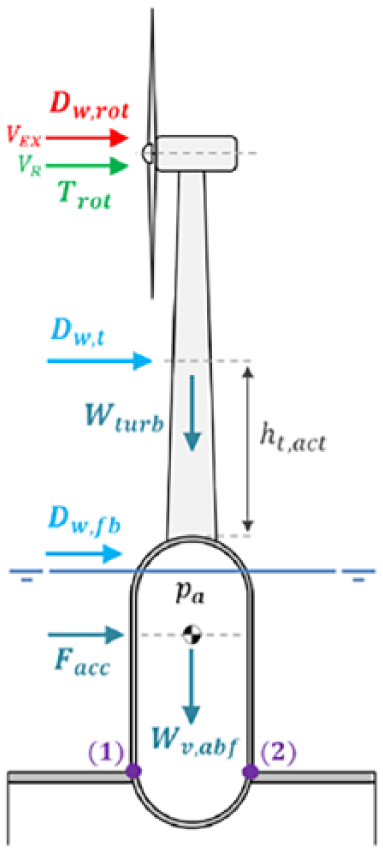
Forces acting on the floater and the stress elements considered.
The TLP consists of a cylindrical vessel and four fairleads whose properties are given in Table 2 for the three platform diameter sizes. Note that the internal volume was maintained constant to ensure that the same storage capacity was maintained. Although the 18-m diameter TLP was based on that modelled in Matha (2009) and Bachynski and Moan (2012), the pressure vessel was modified from having flat end plates (caps) to hemispherical ones in order to reduce the material required to sustain the elevated internal pressure. The thickness of the steel plate used in these hemispherical caps is
Properties and dimensions of the TLP.
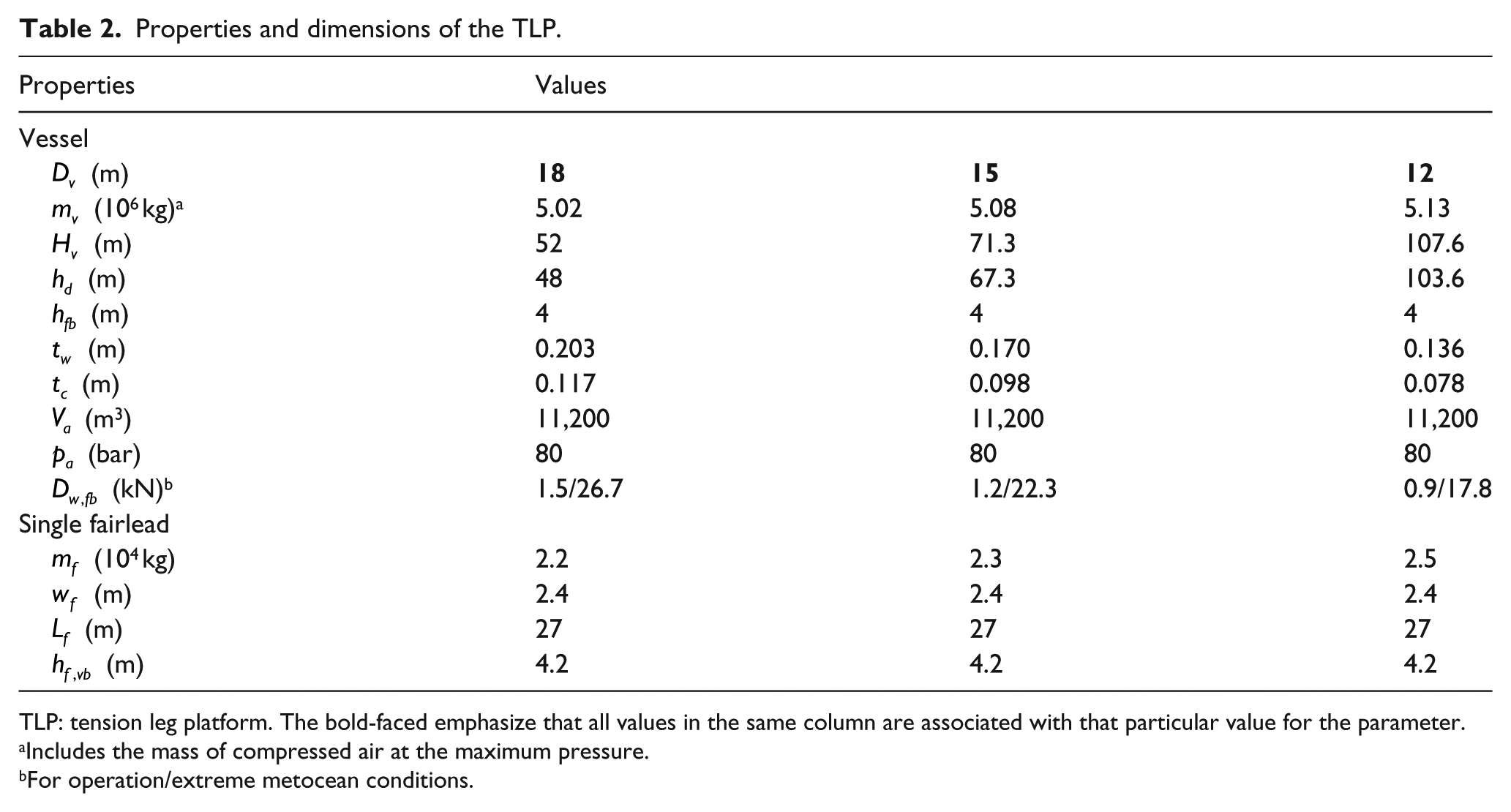
TLP: tension leg platform. The bold-faced emphasize that all values in the same column are associated with that particular value for the parameter.
Includes the mass of compressed air at the maximum pressure.
For operation/extreme metocean conditions.
The horizontal loads result in a bending moment that acts on the cylinder walls, together with the internal pressure and compressive loads due to the weight of the structure. If the fairleads are assumed to act as fixed joints, then the largest internal bending moment would act on the vessel cross-section just above the joints. By considering two surface elements at this point, as shown in Figure 2 and denoted as equations (1) and (2) and analysing the induced combined stresses, the largest stress conditions can be determined. In this way, the wall thickness of the vessel was sized and a factor of safety of 1.5 was applied. Note that the compressive load is due to the weight of the turbine and of the vessel above the fairleads. The cap thickness is dependent only on the circumferential stress due to the internal pressure.
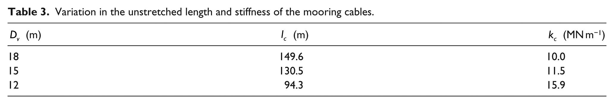
The properties of the anchor and cables are also given in Table 1 where the former is to be produced from concrete and must have a net weight greater than the net upthrust of the floater to ensure that the TLP is held in place under all conditions. The buoyancy to weight ratio of the TLP remained constant at 2.0 for all platform diameters. Furthermore, since the cables are required to maintain the platform in place at a specific freeboard, the resulting tension in each of the eight cables was used to determine the unstretched cable length, and the stiffness is required for any variation in the platform diameter, and hence draught, as shown in Table 3.
Variation in the unstretched length and stiffness of the mooring cables.
In order to link the storage chambers as shown in Figure 1, a simple air umbilical was designed consisting of a tube of carbon-fibre reinforced polymer (CFRP) fitted inside a steel sleeve, as illustrated in Figure 3. The thickness of the CFRP tube

Diagram of the air umbilical indicating the dimensions of the different layers.
On the contrary, the steel sleeve of thickness
Properties and dimensions of the air umbilical.
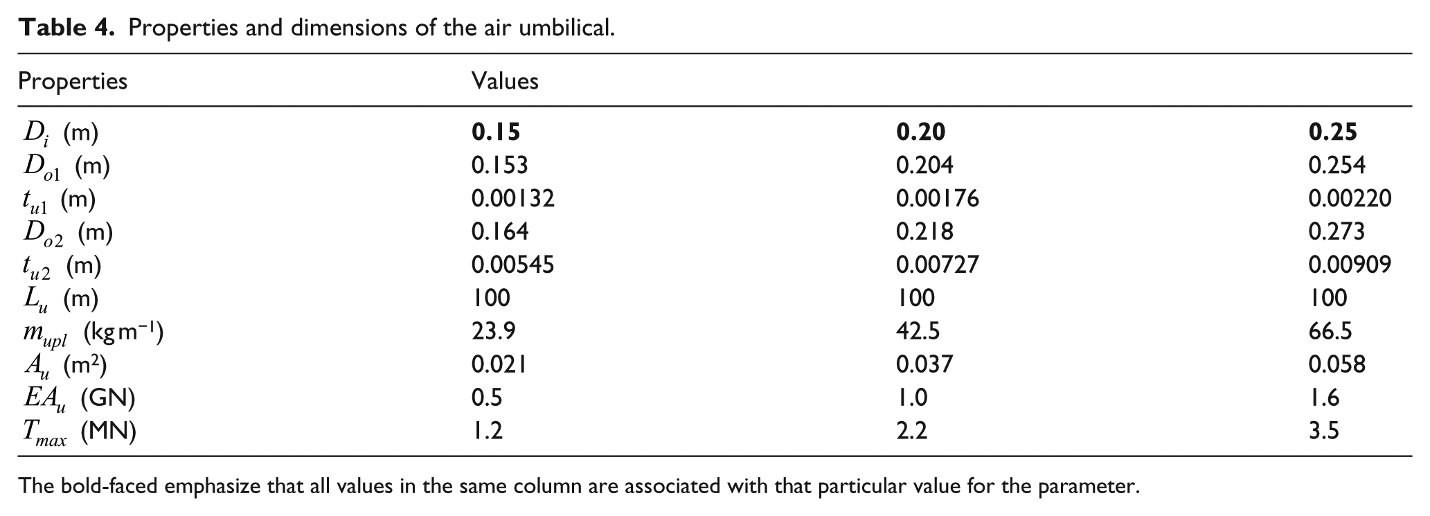
The bold-faced emphasize that all values in the same column are associated with that particular value for the parameter.
In order to determine the energy stored in the system, Buhagiar and Sant (2017) proposed that for an adiabatic process, the energy stored in a liquid piston accumulator of volume

Simple diagram of the system volumes.
where
The maximum pressure is known since the system was designed in its fully charged state, that is, the platform chamber filled with air at 80 bar and the accumulator completely filled with seawater. The adiabatic index was found by interpolating from the data presented for dry air in Engineering ToolBox (2009). However, since this index is determined at the pre-charge pressure, and both (the index and the pre-charge pressure) were unknown, then an iterative process was necessary to determine these properties from equation (2). The specific heat ratio was found to be 1.50 and the pre-charge pressure is 52 bar, resulting in an operating pressure ratio of 1.54. Hence, the energy stored by the system when fully charged was estimated to be 6.65 MWh.
Modelling in ANSYS AQWA
The hypothetical full-scale prototype was modelled in ANSYS® AQWA™ (2016) by a closed hollow cylinder representing the vessel, closed hollow cuboids as the fairleads, linear cables as the moorings and a nonlinear catenary as the umbilical. The turbine was also included in approximate form to help visualise the effect of the response on the rotor position. The generated model is shown in Figure 5 together with the applied wind loads and direction of wave propagation.

Model of hypothetical full-scale prototype in ANSYS AQWA for the 12-m diameter platform with umbilical.
AQWA implements diffraction theory through a higher order boundary element method, whereby surfaces are discretised into a number of flat and curved panels allowing for the pressure distribution to be integrated over the surface and hence compute the hydrodynamic loads. However, this method neglects viscous effects, and so a dummy Morison tube element was included inside the hollow cylinder that models the platform. On the contrary, such elements were not included inside the fairleads, and hence viscous effects on these four structural elements were not considered as they were assumed to be small.
In this case, the tube and the surface are treated separately, with forces acting on each determined independently of the other. However, viscous effects on a slender body are ignored unless Linearized Morison Drag is enabled. Furthermore, since the additional mass and added mass effect of this dummy Morison tube affects the analysis, the diameter was defined to be 1/100 that of the hollow cylinder with a thickness of 0.1 mm in order to minimise the impact. To compensate for this reduction in diameter, the default viscous drag coefficient was proportionally increased by a factor of 100 to 75. The tube length was kept the same as that of the cylinder.
The mass and inertias of the rotor-nacelle assembly, tower, vessel and four fairleads were defined via point masses located at their centres of gravity (CoGs). Moreover, the linear cables for mooring the platform to the top of the anchor, which was not modelled, and hence the anchor (fixed) points to which the cables were attached, were set at a height
The umbilical was modelled as a slack, nonlinear catenary linking a connection point at the centre of the platform base to the anchor. The catenary was divided into 100 elements and Use Cable Dynamics was enabled in AQWA to generate the dynamic forces acting on it and hence better model its motion. The mass per unit length, equivalent cross-sectional area, stiffness and maximum tension of the umbilical were set under Catenary Data – Umbilical Section as defined in Table 4, while the Negative and Positive dZ Range of Expected Connection Point Vertical Motion was set to be 5 m with the number of partitions left as default.
In this work, only regular surface gravity waves generated by the wind were considered. This category of wave can be described by several theories whose applicability depends on the water depth, wave period and wave height (Le Méhauté, 1976). Both operation and extreme wave conditions specified above fall within the applicability range of the Stokes 2nd order wave theory.
Thus, when specifying the model conditions, a regular Stokes 2nd order wave was defined together with three point forces of constant direction representing the wind loads and thrust acting on the rotor, tower and freeboard. These loads were set to act in the x-direction (downwind).
Finally, in order to inspect the hydrodynamic performance of the model, four different graph types were used. Six graphs of type RAOs (Distance/Rotation vs Frequency) [RAOs: response amplitude operators] were included to generate the frequential response for all six degrees of freedom of the CoG of the model. They were likewise investigated in the time domain through additional graphs of type Structure Position – Actual Response. A third graph of type Structure Acceleration – Actual Response was also inserted to obtain the surge acceleration of the model CoG, hence allowing for the acceleration force described in Figure 2 to be calculated. Finally, a Cable Forces – Whole Cable Forces – Tension type graph was created to inspect the temporal variation of the tension in the eight cables. Other relevant settings required for the simulation are given in Table 5.
Relevant settings defined in ANSYS® AQWA™ for the model of the hypothetical full-scale prototype.
Results and discussion
The conceptual full-scale prototype was modelled in ANSYS AQWA and solved in the frequential and temporal domains to generate the RAOs, the displacement response in all six degrees of freedom and the tension developed in the mooring chains.
A preliminary simulation of the model was carried out to determine the surge acceleration of the floater and hence the force due to this acceleration. The design calculations were updated with this force and the simulation was rerun. The responses for each platform for a specific degree of freedom and metocean conditions were superimposed to facilitate comparison.
Influence of platform diameter
With regard to the physical characteristics of the TLP, it can be noted (see Table 2) that by reducing the diameter from 18 to 15 m, the cap and wall thicknesses decreased by 16.7%, whereas the draught increased by 40.2%. Similarly, further cutting the diameter to 12 m resulted in a thickness reduction of 19.9% and a rise in draught by around 53.9%. These observations were expected since, for the same internal pressure, cylindrical vessels of smaller diameters develop lower induced stresses, hence allowing for reduced wall thicknesses to sustain the pressure load. Since the draught increased at a faster rate than the reduction in steel plate thickness, the overall mass of steel required for the platform was found to increase with decreasing diameter. In fact, for TLP diameters of 18, 15 and 12 m, the mass of steel was found to be 4047, 4119 and 4179 tonnes, respectively. Note that the mass of the original design by Matha (2009) was of 3971 tonnes, excluding the ballast.
As was expected, the superimposed plots for the RAOs did not change for either of the two metocean conditions, since the model geometry remained constant for both. The resulting surge RAOs are shown in Figure 6 and indicate that at lower wave frequencies, the response in surge decreases with the platform diameter. In fact, for a wave frequency of 0.1 Hz and a wave height of 1 m, the surge response decreases by 44.8% between the 18- and 12-m diameter platforms. However, as the frequency increases towards 0.3 Hz, the difference in response between diameters becomes negligible.
Frequential variation in the surge RAO of the model for different platform diameters (in operation conditions).
With regard to the heave RAOs presented in Figure 7, the 18-m diameter platform appears to exhibit the smallest response at its natural frequency. However, the computation at this frequency is very sensitive and it is highly likely that the frequential grid was not refined enough to accurately capture the peak of the relationships shown. Thus, rather than the magnitude of the response, the range in which the resonant frequency lies was considered instead. By this interpretation, one may note that the smaller the diameter, the lower the natural frequency and therefore the higher the exciting wave period. For a diameter of 12 m, resonance will occur at around 15.5 s, whereas for 18 m, this will occur at approximately 10.8 s. Thus, only the former would exhibit a natural period higher than that for extreme conditions.
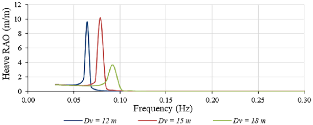
Frequential variation in the heave RAO of the model for different platform diameters (in operation conditions).
Finally, for higher frequencies and, therefore, lower wave periods (i.e. calmer sea states), the pitch RAO will be larger for smaller platform diameters, as illustrated in Figure 8. In fact, for a wave period of 10 s and height of 1 m, the increase in response from the 18- to 12-m diameter platform is around 350%.

Frequential variation in the pitch RAO of the model for different platform diameters (in operation conditions).
With regard to the temporal responses for the prototype model, those for surge, heave and pitch are presented in Figures 9 to 11 for operation conditions, that is, for the rated turbine wind speed of 11.4 ms−1, a wave of height 4 m and a period 10 s. As may be observed, the responses for each platform diameter are of a similar nature. The following analysis deals with the maximum response at steady state since the responses generally oscillate between zero and some positive value and so it was deemed necessary to identify the maximum motion exhibited by the model.
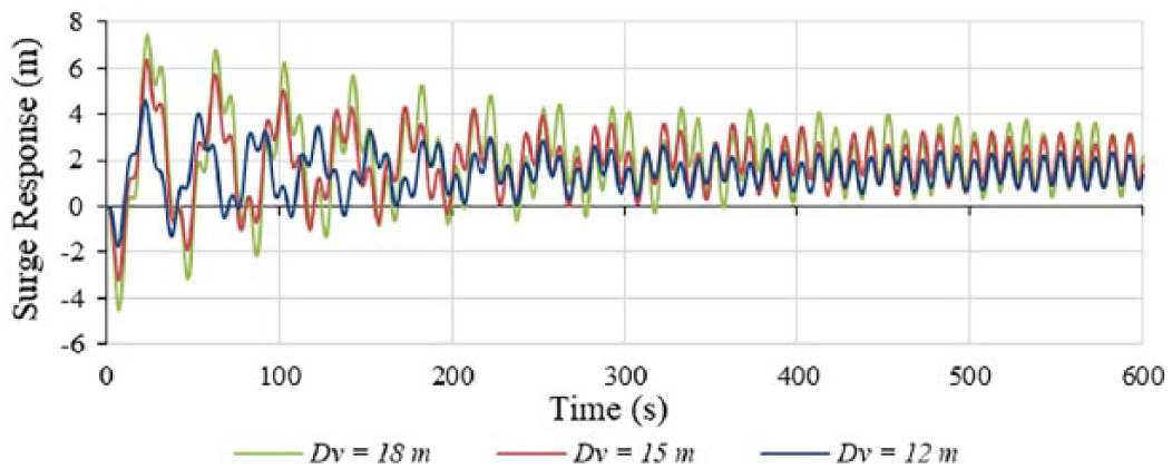
Temporal variation in the surge response of the model for different platform diameters (in operation conditions).

Temporal variation in the heave response of the model for different platform diameters (in operation conditions).
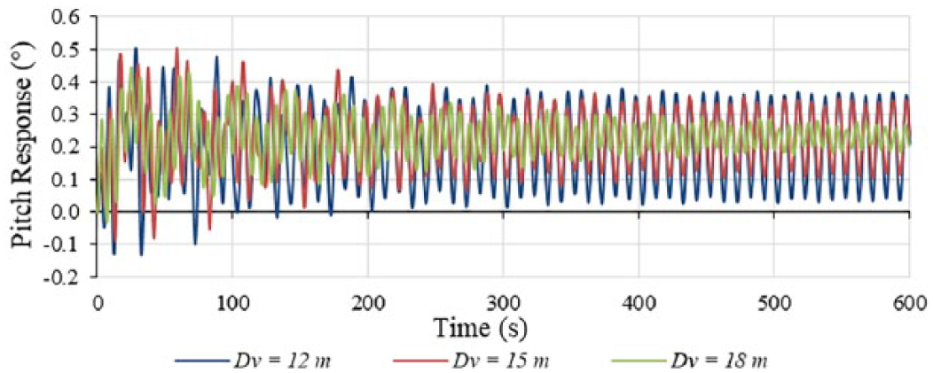
Temporal variation in the pitch response of the model for different platform diameters (in operation conditions).
For the surge response for both operation and extreme conditions, the 12-m diameter platform exhibited the best hydrodynamic performance with a smaller temporal response. The floater was noted to oscillate about a mean located downwind from the initial position by a distance which decreased between the 18- and 12-m diameter platforms by 25% and 32.8% for operation and extreme conditions, respectively. Moreover, the maximum surge downwind was observed to drop by 37.4% when reducing the diameter through the same range.
The 12-m diameter platform also yielded the less severe heave response for both metocean conditions, with the maximum steady-state response decreasing by around 80% from that generated for the 18-m diameter. In addition, the mean position about which the platform heaved was noted to lie above the initial position of the float, though tending towards this initial point as the TLP diameter decreased.
On the contrary, the pitch responses for operation conditions indicated that the larger diameter platform was significantly better than the smaller one, with the latter increasing the maximum pitch by 30.2%. Conversely, for extreme conditions, the larger diameter yielded a beating response which was ignored. Of the remaining two platform sizes, the 12-m diameter TLP reached steady state at a much faster rate than the 15-m one, and the maximum pitch response was 81.5% smaller. It was also observed that once the responses had stabilised, the floater oscillated in pitch about a mean position, whereby the rotor hub was oriented at a slight upward angle to the horizontal.
By analysing the hydrodynamic results generated for the model in ANSYS AQWA, it was noted that when the TLP had an external diameter of 12 m, a better hydrodynamic performance was observed in all degrees of freedom except pitch. However, upon further investigation of the pitch RAOs for the 12-m diameter platform, the response in operation and extreme conditions were found to be 0.5° and 0.78°, respectively. Such angles result in rotor-hub movements, which are small relative to the size and scale of the turbine, and are hence unlikely to impact turbine performance significantly.
Based on the above analysis, the best platform diameter was deemed to be that of 12 m, as the aggravation in the pitch response observed for this size was considered to be of little significance and the steel plating required for the construction of the vessel was the thinnest. This diameter was then considered in the analysis investigating the effect of the umbilical inner diameter on the structure response.
Influence of umbilical diameter
Prior to analysing the effect of inclusion of the air umbilical in the model, a number of observations can be made regarding the umbilical’s physical characteristics as listed in Table 4. As can be noted, increasing the inner diameter of the umbilical from 0.15 to 0.2 m resulted in an increase of 34% in both the CFRP and steel wall thicknesses. When increasing from 0.20 to 0.25 m, this percentage dropped slightly to a 25% increase. Overall, this implies that the total masses of the umbilical were of 2.23, 3.96 and 6.18 tonnes for inner diameter of 0.15, 0.20 and 0.25 m, respectively.
For the umbilical study, the model for the 12-m diameter platform was updated for each umbilical design and the simulation was rerun. However, this time only operation conditions were considered. Note that in order to broaden the range of analysis, and hence draw wider conclusions, the generated results were compared to those of the model without an umbilical.
The plots for the RAOs, such as those for surge presented in Figure 12, indicate no difference attributed to the inclusion of the umbilical and varying between the three inner diameters. This was expected since the geometry of the platform did not change among the cases considered and the additional mass of the umbilical was negligible compared to that of the TLP. Furthermore, the temporal responses showed that at most, there was only slight variation across the range of scenarios considered, as may be noted from Table 6. The results presented are the maximum steady-state response for selected degrees of freedom.
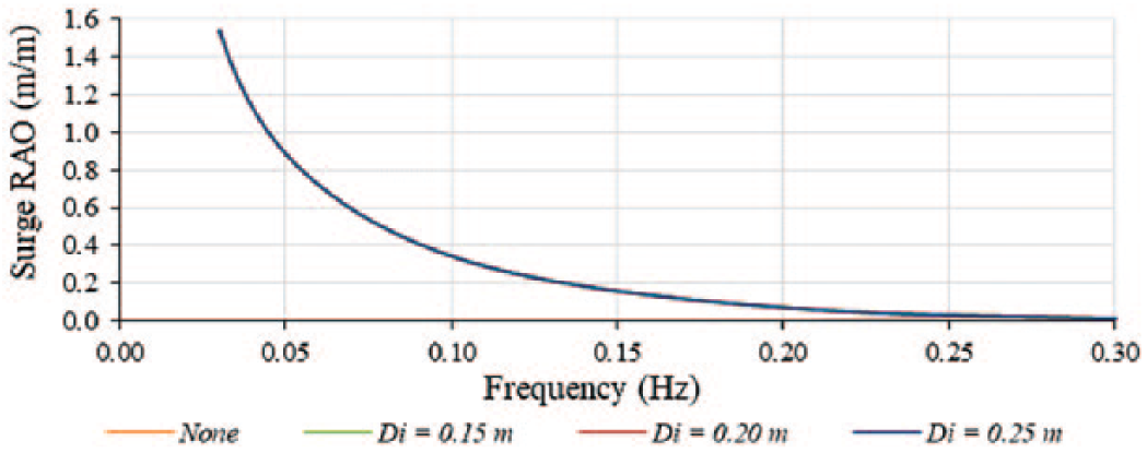
Frequential variation in the surge RAO of the model for different umbilical inner diameters (in operation conditions).
Maximum steady-state response of the model for different umbilical inner diameters (in operation conditions).

The temporal response generated in surge indicated a slight improvement in performance when the umbilical was introduced, with a reduction in translation being observed for larger inner diameters. However, the maximum reduction was of 0.128% explaining why no deviation can be observed in the plot presented in Figure 13.
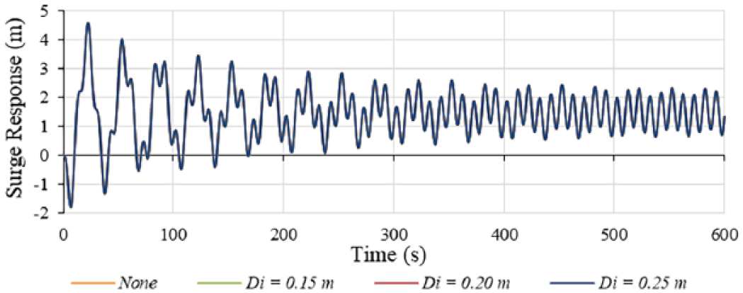
Temporal variation in the surge response of the model for different umbilical inner diameters (in operation conditions).
Similarly, the response for the model in pitch yielded marginal improvements for increasing inner umbilical diameter. The magnitude of the maximum pitch observed decreased by 0.054% between not including an umbilical and including one with a 0.25-m inner diameter.
However, the temporal heave response presented in Figure 14 shows by far the largest deviation between the generated data. There was a comparatively marked improvement of 8.4% when introducing the smallest sized umbilical relative to the no umbilical case, with the platform translating vertically upwards to a reduced maximum. In fact, a trend may be observed with the response magnitude becoming smaller for larger umbilical diameters, and an improvement of up to 16.8% was noted over the range considered. That said, this amounted to a 7.2-mm reduction in the maximum heave response, which is negligible given the size of the hypothetical full-scale prototype.

Temporal variation in the heave response of the model for different umbilical inner diameters (in operation conditions).
It was thus noted that when the air umbilical was included in the model, the TLP generally exhibited a better hydrodynamic performance for all degrees of freedom with a marginal improvement for wider umbilical inner diameters. Hence, it was concluded that an inner diameter of 0.25 m would yield the best performance. However, this would require increased material costs and impart a very limited hydrodynamic improvement in the overall system.
Conclusion
Analysis of the simulation data showed that the 12-m diameter platform was the best of the three options considered. The reason for this being that the smaller diameter allows for thinner steel plating to be used to construct the pressure vessel, hence lowering manufacturing complexity and costs, while providing the better hydrodynamic characteristics overall due to the larger draught.
Furthermore, the addition of a pneumatic umbilical was found to be beneficial to the hydrodynamic performance of the TLP in all degrees of freedom, and that the larger umbilical inner diameter of 0.25 m imparts the largest, albeit marginal improvement to the characteristics.
A number of aspects could be developed further. More complex models of the hypothetical full-scale prototype should be produced using software that couples the aerodynamic and hydrodynamic loadings. In addition, a more detailed and realistic design assessment of the umbilical should be carried out.
Footnotes
Appendix 1
Acknowledgements
The use of ANSYS® AQWA™, Release 17.1, under licence ANSYS Academic Research Mechanical and Computational Fluid Dynamics is acknowledged.
Declaration of conflicting interests
The author(s) declared no potential conflicts of interest with respect to the research, authorship, and/or publication of this article.
Funding
The author(s) disclosed receipt of the following financial support for the research, authorship, and/or publication of this article: This work is part of the Project FLASC (R&I-2015-044-T) being carried out in collaboration with the industrial partner Medserv p.l.c. and financially supported by the Malta Council for Science & Technology through the FUSION R&I Technology Development Programme.