
Abstract
Renewable energy sources are growing fast. Nowadays, much effort has been made by inventors to devise new and more efficient configurations of wind turbines. This article describes the mechanical design and resultant force dynamic simulation of an innovative horizontal-axis semi-exposed wind turbine structure. The innovation in wind turbine structure includes the flat shape of its blades and their orientation towards the wind that minimizes the axial component of wind force on the shaft bearings. As a result, wind power is fully utilized to generate a useful rotary force that drives the generator rotor. This enhances the efficiency of the turbine as compared to complex shape blades in traditional horizontal-axis wind turbines. The distinctive feature of the system is also an oscillating shield that automatically protects the generator shaft from overspeeding at extreme wind speeds and, therefore, from generating power above its nominal capacity. The overspeeding may even cause physical damage to the generator. The force analysis of the new wind generator has been conducted for various wind conditions by using ANSYS Fluent. The results are compared to a traditional three-blade horizontal wind turbine to prove the ability of the new semi-exposed wind turbine to collect more driving torque on the shaft. The results of the simulation show the efficiency of the system and the advantage of using this system with the overspeed shield protection.
Introduction
In the modern world, one of the primary goals of the energy sector is the development of renewable energy sources to reduce greenhouse gas emissions. As a result, electricity production from renewable energy sources such as wind, hydropower and solar has been increased in recent years. It is reported that 24% (2195 GW) of total electricity was generated by hydroelectricity and renewable energy sources in 2017 (BP Statistical Review of World Energy, 2018). According to the WWEA Half-Year Report (2016), wind energy capacity has reached 456.5 GW, which is 4.7% of the total electricity demand in 2016. By the end of 2017, the capacity of wind energy reached 539 GW, 25% of total renewable energy (BP Statistical Review of World Energy, 2018). Despite that solar photovoltaic (PV) has more attention than another renewable energy sources, wind power provided more than half of renewable growth (BP Statistical Review of World Energy, 2018; International Renewable Energy Agency (IRENA), 2018; WWEA Half-Year Report, 2016). Generally, wind turbines are classified depending on the axis of rotation (horizontal and vertical) and location (onshore and offshore) (Shen and Meisen, 2012; Thyagarajan and Bhalla, 2014; Tong, 2010). Horizontal-axis wind turbines (HAWT) are widely used due to high efficiency. However, aerodynamic modelling is required to identify the optimum height of the tower, control systems and blade and rotor size (Thyagarajan and Bhalla, 2014). In addition, depending on rotor location, HAWTs are classified into two types: upwind and downwind. Rotor is facing the wind for upwind, whereas wind passes the tower and nacelle first and only then reaches the rotor for downwind.
However, Cianetti et al. (2018) include additional crucial components such as yaw motor, gearbox and foundation. The principle of operation of HAWT is based on the aerodynamic lift. When the wind reaches the rotor and blades, it starts rotating. The rotor is connected with the low-speed shaft, which is connected with gearbox creating high-speed motion. In turn, the high-speed shaft is linked with the generator. One of the important considerations during the design is the blade. Mouhsine et al. (2017) study the effect of the blade on the performance of the wind turbine. It was determined that blades should have a low angle of attack for HAWTs because it corresponds to high aerodynamic lift, which is directly proportional to efficiency. Another concern in the design of HAWTs is consideration of protection components to avoid damage at high wind speeds (Thyagarajan and Bhalla, 2014). According to Sorensen et al. (2009), there are two key speed terms. The first is ‘cut-in speed’ at which the wind turbine starts to generate power. The second is ‘cut-off speed’ at which the wind turbine must be stopped to avoid possible damage of rotor and other components. Rossander et al. (2017) propose the control system, which is based on keeping the turbine rotation at preferable operation region. The operation principle of the controller is based on torque control. The reference torque as a function of rotational speed is determined, and depending on that, behaviour of the turbine is controlled (Iordanov et al., 2017). Vertical-axis wind turbines (VAWT), in contrast to HAWT, are mostly used in an urban area due to the ineffectiveness of HAWT in chaotic, less predictable, turbulence region (Gulve and Barve, 2014). The working principles of VAWT are based on the difference of aerodynamic drag on each blade (concave and convex) (Pope et al., 2008; Roy and Saha, 2013). Generally, VAWTs generate power by rotating about a vertical axis (Zemamou et al., 2017). In addition, VAWTs are more applicable due to the ability to operate regardless of height and wind speed (Shah et al., 2018). Moreover, it has low cut-in speed, has less structural support and does not require a yawing mechanism. However, the main drawbacks of the turbines are not only low efficiency but also the absence of reliable performance prediction.
There are two main types of VAWTs, namely, Savonius and Darrieus (Pope et al., 2010). According to Zemamou et al. (2017), Savonius type of wind turbine does not depend on wind direction and can start at low speeds. It has 31% efficiency theoretically, but in practice, it is only 16% (Shah et al., 2018). Low efficiency can be explained by the effect of the drag force on each blade (Pope et al., 2010). Generally, Savini wind turbine consists of two or more half cylindrical shape blades on each side of the rotating shaft (Saha et al., 2008). The performance of the turbine depends on a number of blades and the shape of the blade. The shape of Darrieus blades is usually a NACA style, with different layouts and proper distance from the rotation axis (Kumara et al., 2017). This type of turbine does not self-start and requires electrical support to start (Dominy et al., 2007). However, the proper design of blades enables the turbine self-start at 4–5 m/s wind speed. The main difference from Savonius type of turbine is that working principle is based on not only drag but also lift forces (Dominy et al., 2007). It can be applied in urban areas due to low cost and the ability to operate at turbulence and frequent-change environment (Pope et al., 2010). Generally, theoretically and practically, the efficiency of Darrieus type of VAWT is around 40% (Kumara et al., 2017; Shah et al., 2018). Gupta et al. (2008) and Carrigan et al. (2012) propose a new design for Darrieus and Savonius turbines to increase efficiency by combining them. Sarkar (2017) proposes an alternative design of wind turbines without blades. It converts mechanical energy into electricity by aerodynamic vorticity. The main advantage of this design is lack of frictional loss due to the absence of sliding joints. It has approximately 40% efficiency. Wind turbines also can be used as a building cooler by the construction of building around wind turbines (Gharakhani et al., 2017). Buildings create a tube around the turbine, which allows catching air and cooling. The proposed design of a new horizontal-axis semi-exposed wind turbine (HASWT) structure aims to increase the wind energy utilization as compared to modern HAWT and VAWT due to the bent shape of the blades. Because of the flat shape of its blades that are directly facing to wind flow, this design minimizes the axial component of the wind force that adversely affects the rotor bearing and enables only a useful rotary component of driving force on the generator shaft. This will increase the efficiency of the turbine as compared to the traditional wind turbines where part of the wind force is affecting the rotor bearing. The approximate point force analysis (when the results of wind forces are applied at the centre of the blade area) and preliminary proof of work efficiency of HAWT have been described in detail in the article (Mir-Nasiri and Seitenov, 2016). This article has a purpose of expanding this work to analyze the work of HAWT under distributed forces that are applied on the surface of the blades and the shield by using ANSYS Fluent software.
Materials and methods
Structural design of HASWT
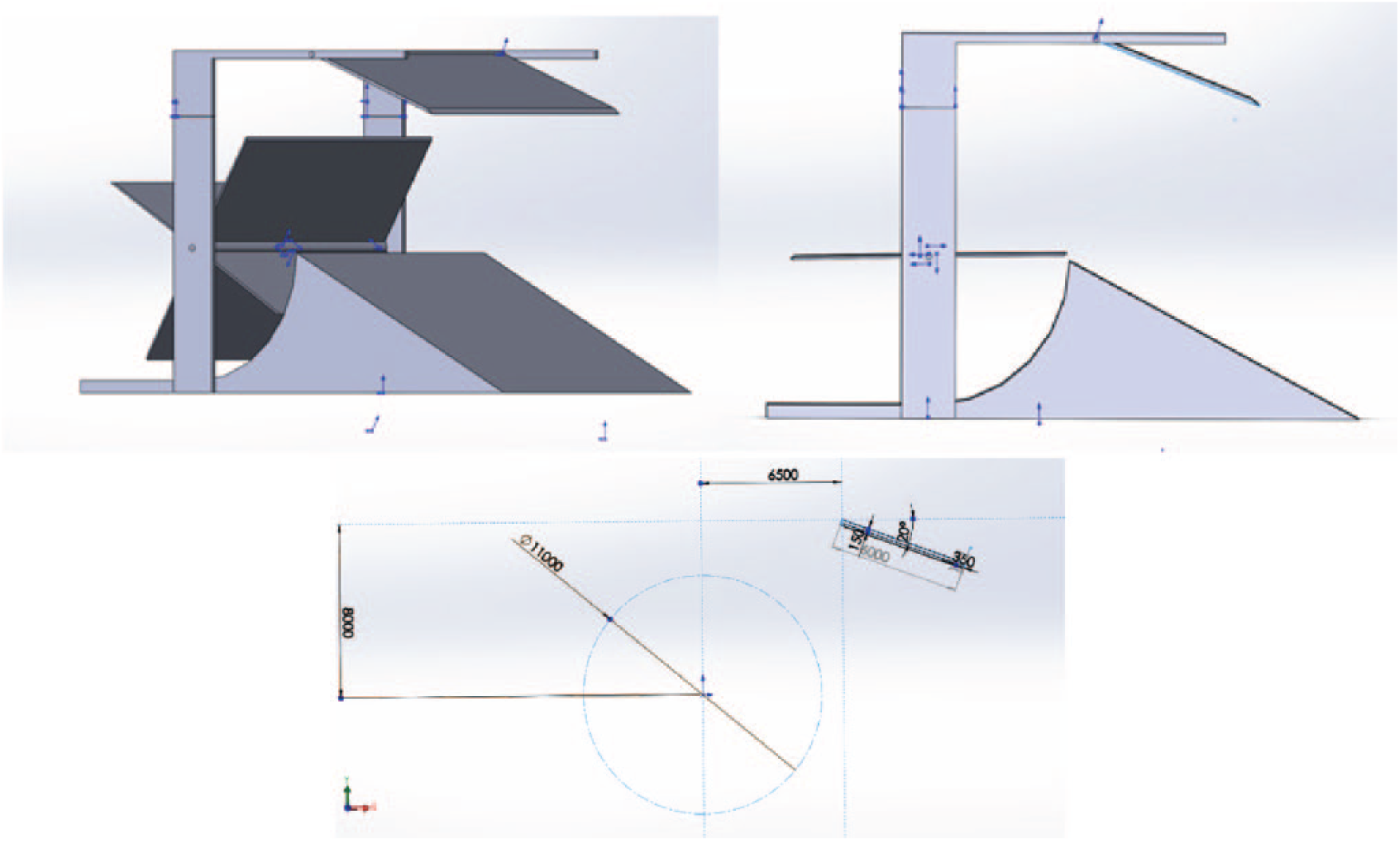
The three-dimensional (3D) schematic view of the designed wind turbine system is shown in Figure 1. The turbine generator is located on an elevated rotary platform (1). The generator shaft (2) is mounted horizontally and fitted with four orthogonal and slightly convex at the edges (not shown in the figure) flat blades (3). There are two sets of such blades that are rigidly connected along the rotating shaft. The usage of two sets of blades instead of one helps to smooth the fluctuation of the rotary speed of the shaft. In this article, only one set of blades is taken for calculation of wind torque on the shaft. In each set, only two blades are subjected to a stream of horizontal wind flow at any time. Thus, the blades that are below the horizontal axis of the shaft are shielded from the wind by the slopped shape platform (1). The platform (1), in turn, is connected to a vertical post (4) by means of thrust bearings and it is able to rotate about its vertical axis. The platform rotation is naturally controlled by the vertical tail fin (5) that is rigidly attached to it. The fin ensures that the blades are always facing the direction of the wind blow.

Schematic view of the designed turbine system.
The distinctive feature of the designed system is the oscillating shield (6). It is joined to the platform by means of horizontal hinge (7), and it is able to rotate about its axis. However, the amount of rotation is controlled by the set of tension springs (8) that connects shield (6) to platform (1). The details of the shield connections are shown in Figure 2. The amount of shield rotation solely depends on the strength of blowing wind and the selected spring constant. In non-deformed condition, the springs are in the state of initial tension that prevents the shield from being rotated. In this condition (acceptable wind speed), wind can easily pass the gap between shield (6) and platform (1), reach the generator blades and rotate the shaft with maximum power. If the wind speed increases beyond the set value, that is, its value becomes sufficiently enough to overcome the initial tension, the spring will yield. The shield then turns and partially obstructs the winding passage to the blades. As a result, the gap becomes smaller, and this, in turn, slows down rotor rotation at extreme (unacceptable) wind speeds. The more is the wind speed, the less is the torque on the shaft. The convex shape of the blade edge (not shown in Figure 1) is additionally introduced to reduce the air turbulence at edges of the blades.

The windshield of the system.
Force analysis of HASWT by ANSYS software
The simulation is conducted based on the rotor of the Kingspan Wind KW6 wind turbine. According to the specification, it has a pick power generation of 6.1 kW, rotor shaft radius of 1.2 m and mass around 6000 kg. The selected one set of blades has 2 m width and 4 m height (Figure 1). The shield width is selected to be WS = 4 m wide to cover both blade sets. The maximum wind speed that causes full stretch of the shield is selected to be vmax = 25 m/s. Blade height Hb = 4 m defines the height of shield HS = 6 m.
The analysis of the dynamic forces and torques on the blades can be separated into two different cases:
Normal wind speed conditions (no-shield involvement), when the shield springs are strong enough to keep the shield in its original position (i.e. it does not obstruct the wind at all).
This corresponds to a wind speed of approximately less than 10 m/s.
Extreme wind conditions (shield involvement) when the wind pressure is strong enough to turn the shield plate, and as a result, it will partially obstruct the wind stream.
This corresponds to wind speed approximately more than 10 m/s but less than 25 m/s.
Forces analysis of the shield under varying wind speed and selection of springs
The first step of this analysis is to analyze the deflection of the shield under various wind conditions and select the proper springs that will hold it from deflection for speeds less than 10 m/s and start deflecting when speed exceeds 10 m/s as well as be able to hold the fully defected shield when speed reaches maximum assumed speed of 25 m/s. This methodology can be used successfully for other possible boundary values of wind speeds, if necessary. The model of the shield was constructed using Solidworks and parameters given in the article (100, ‘Conceptual Design and Simulation of Horizontal Semi-exposed Wind Turbine (HSWT) Structure’). Computational domain has a size of 22.5 × 16 × 16 m, that is, large enough to include the rotor blades later into the simulations (Figure 3).
Shield dimensions and location.
Patch Conforming method using tetrahedrons was chosen to save time for simulations. The total number of elements is approximately 310,000. The set-up domain for an inlet wind speed of 10 m/s and the selected initial shield angle of 20° are shown in Figure 4.

Set-up of a domain with an inlet wind velocity of 10 m/s.
Figures 5 and 6 show the pressure distribution due to wind flow and velocity contours at the centre plane of the shield.
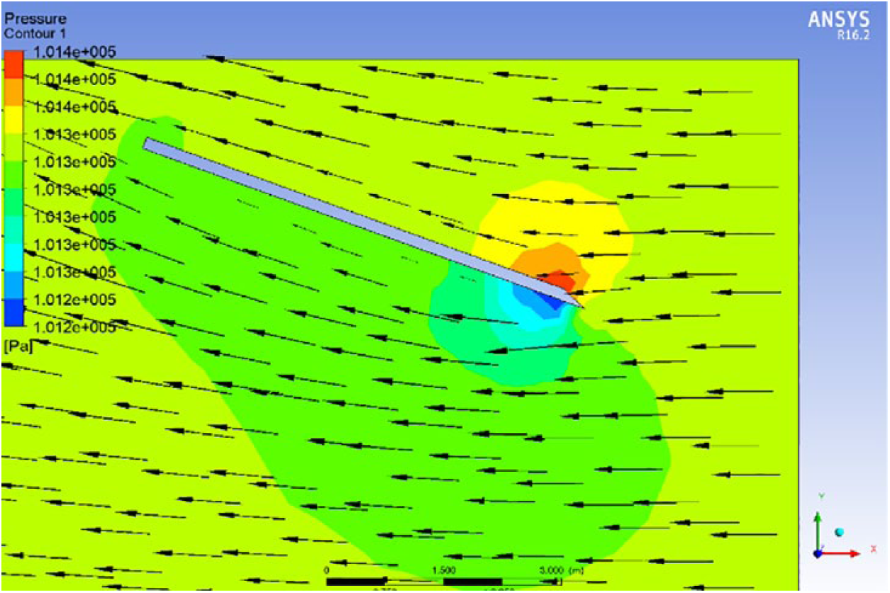
Pressure distribution.

Velocity distribution.
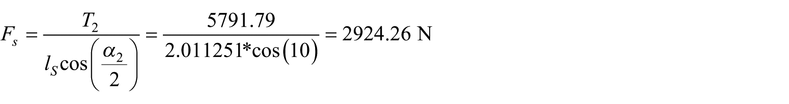
In order to calculate torque on the axis of a shield, the new coordinate frame was specified to predict its value using a function calculator accurately. As a result, the torque acting on a shield around z axis revealed to be −3401.4 N m, which is apparently in a clockwise direction. Springs selection is based on the following methodology.
In Figure 7, Fs is axial load on the extended spring, Hb is length of the blades, Hs is length of the shield, x is the amount of opening (gap) for the wind to reach the blades, αs is the angular position of the shield with respect to the horizontal axis and lS = OA is the distance from pin O to the point A where spring is attached to the shield. Figure 7 shows the shield positioning when it is not deflected and the final position when it is at full deflection. The distance which is left open due to windshield position is dependent on the wind speed attacking the shield surface and selected spring parameters. The deformation of spring is the difference between initial and deformed lengths of the spring
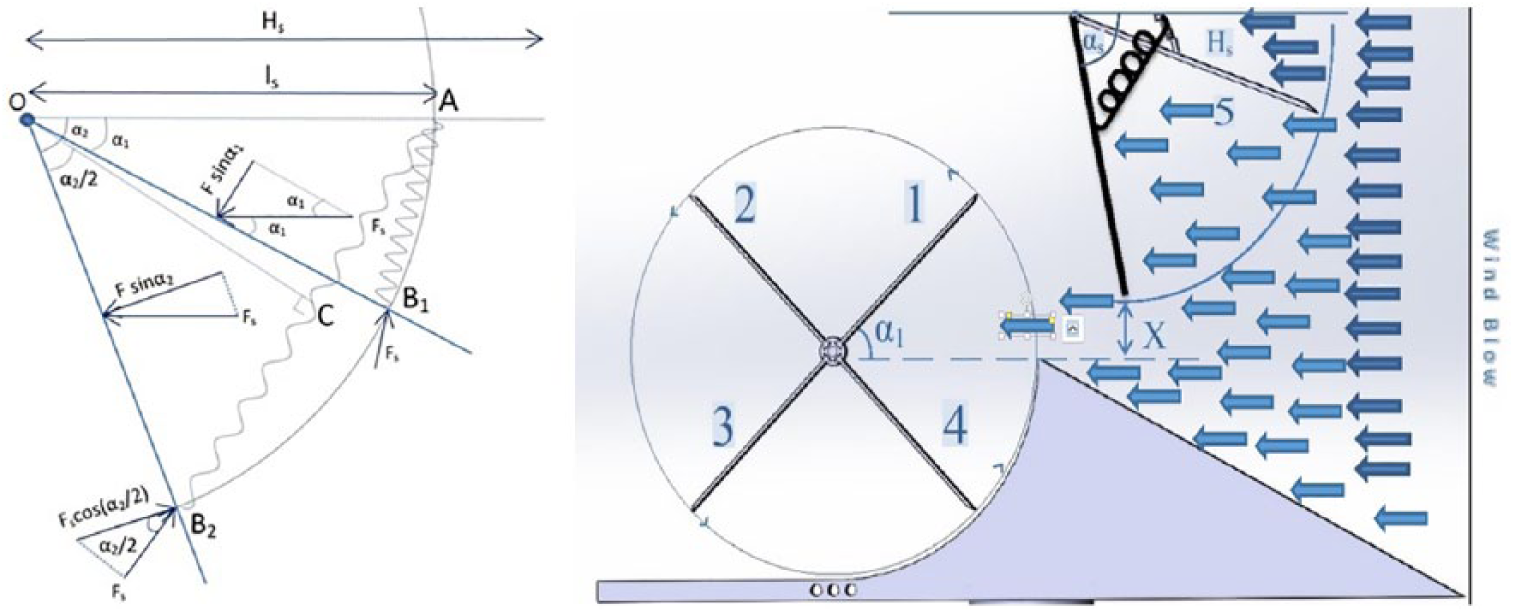
Wind shield initial and final positions.
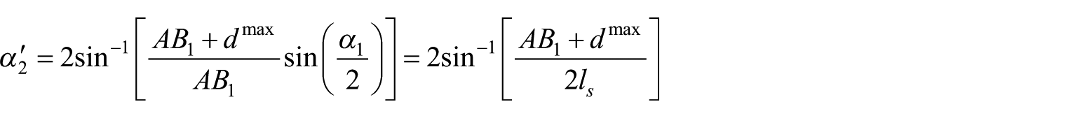
Deflection of the spring depends on where the spring has been attached. From Figure 10, it follows that

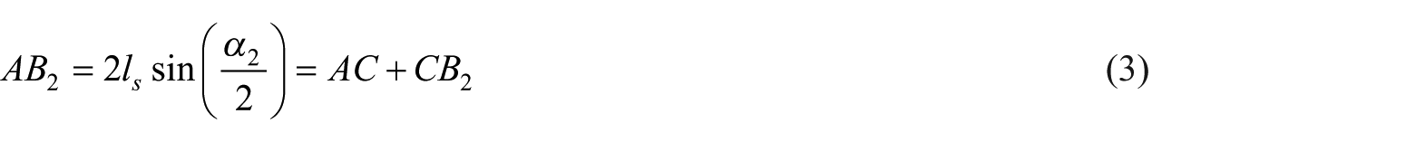
where ls is the distance from the pivot to the point where the spring is attached. From equations (1) and (2), it follows that maximum deformation is
Dividing equation (3) by equation (2) yields the below expression
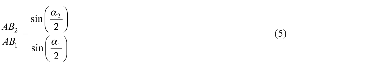
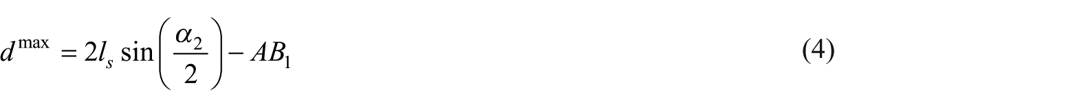
Maximum allowed angular rotation of the shield can be found from equation (4)
The final angle of the shield due to strong wind force can be calculated from the torque balance equation
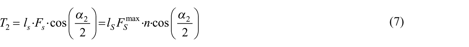
where T2 is the calculated torque value for the maximum wind speed selected; Fs is axial load on the deformed spring;
For the initial torque due to 10 m/s, the torque balance equation is the same
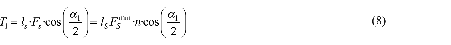
where
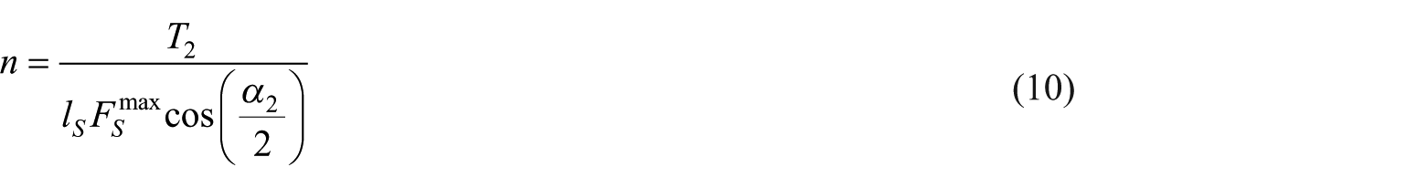
From these equations, it clear that the spring can be selected based on the maximum load

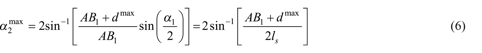
It may be the case that one spring is not sufficient to keep the shield in a necessary position against the wind force. For these purposes, number of springs would be attached parallel with equal distances from each other. The number of springs necessary to support the shield against the maximum wind speed can be derived from the equation (4)
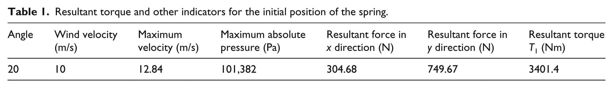
Spring attached to the shield should have parameters such that it starts yielding at 10 m/s. The maximum deformation of the spring should be at the shield position of 35° with a horizontal line. Thus, these cases were considered in the previous section using ANSYS CFX. From ANSYS CFX simulation results, the results for the initial position of the shield have been derived as shown in Table 1.
Resultant torque and other indicators for the initial position of the spring.
In order to select the spring, it is necessary to take into account the desired initial and final positions of the shield. Springs must have such properties to withstand against the wind with a velocity of 25 m/s and not deflect more than 35° with respect to a horizontal plane. It is clear that the selection of spring by constraining two extremum angles leads to the increased number of springs to support maximum force. In order to select the spring, the following order of operations is established.
First, there is a condition that the minimum force required for spring deflection will not allow yielding the shield due to the torque corresponding to 10 m/s. Combining equations (2) and (8)
From equation (11), the necessary condition to stand against the wind force due to initial speed can be derived
The formula above requires selecting the minimum number of springs required to stand with the wind at an initially selected angle of 20° for 10 m/s. In this case, the minimum number of springs calculated was 10 from equation (12). After selecting the spring, the attachment point is defined using equation (9). The final angle
where
It is clear that

where
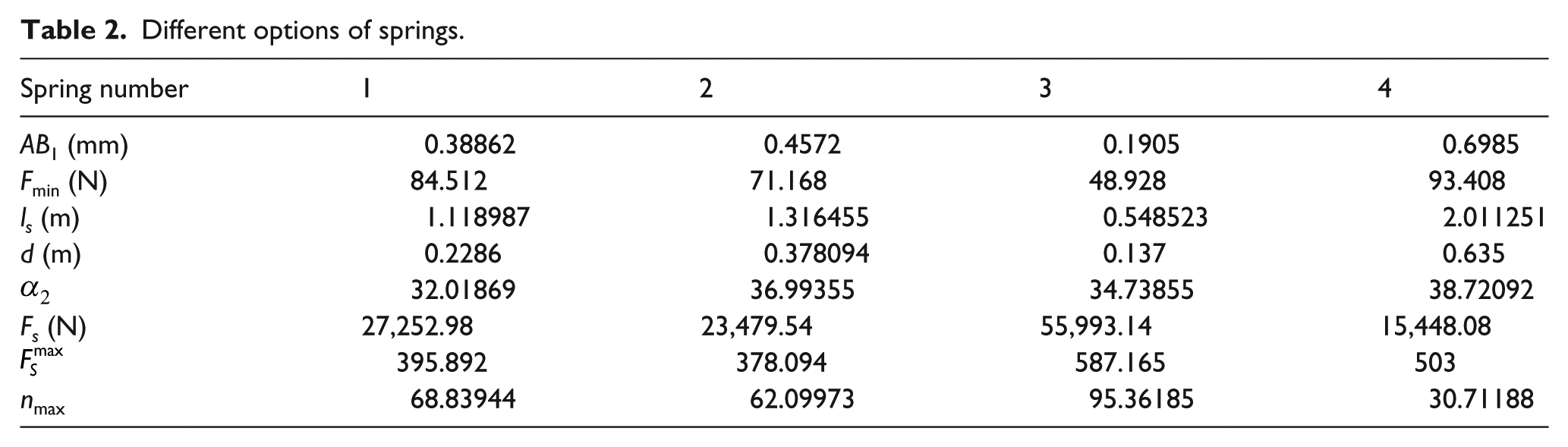
In this approach, the final position of the shield is not constrained to 35°. Four different springs were chosen with different initial lengths and deflection lengths. The results are listed in Table 2.
Different options of springs.
It is important to mention that T2 values for each case were calculated using ANSYS simulation according to the final angle
As the specific spring has been chosen, it is necessary to reconsider the angles of shield deflection by the selected spring specifications (Table 3). In order to do that, the velocity of the wind speed was increased from 13 to 25 m/s in increments of 2 m/s to determine the gradual deflection of the spring. From equation (7), the total load acting on the springs can be derived:
for
Selected spring parameters.

There is a necessary condition that the total force acting on the springs should be larger than the minimum load for the deflection of springs not to yield at small velocities

Hence, it is clear that wind speed of 13 m/s is the minimum value of speed required to start deflection of springs for the selected spring specification. The difference of forces acting on the final and initial positions of the springs can be used to find the deflection of the spring

Now, deflection of the single spring is calculated using the formula below

From equation (1), it follows that

The final angle corresponding to the certain wind velocity can be calculated using equation (6)
Substituting values to derive

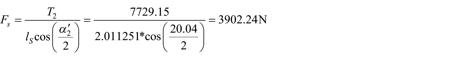
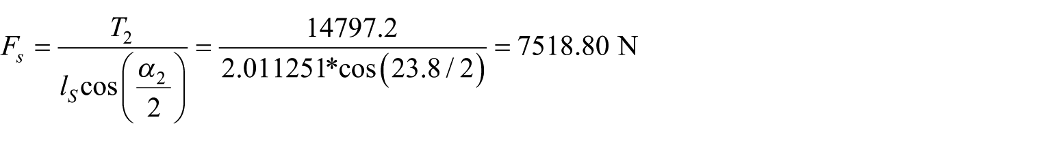
From the calculation above, it can be noticed that chosen spring specifications allow deflection of the shield from 20° when the wind velocity reaches 13 m/s. As such, it is possible to recalculate the values of torque according to adjusted angles and velocities. Increasing the speed in equal increments, it is possible to find out the degree of deflection per increase of velocity. Increasing the velocity to 15 m/s, the torque value derived from ANSYS simulation equals to 7729.15 N m. Therefore, the angle of the corresponding deflection can be calculated as follows


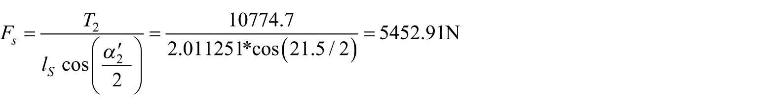
Repeating the same operation by increasing the wind velocity to 17 m/s yields the following results


When the wind speed for 23.8° was increased to 19 m/s, the following results were calculated


In the same manner, wind velocities from 13 to 25 m/s in increments of 2 m/s have been simulated to derive new shield yielding angles. The results of velocity distribution and pressure patterns for initial speed of 13 m/s and final wind speed 25 m/s with corresponding shield deflection angles are illustrated in Figures 8–11.

Velocity distribution (

Pressure distribution (
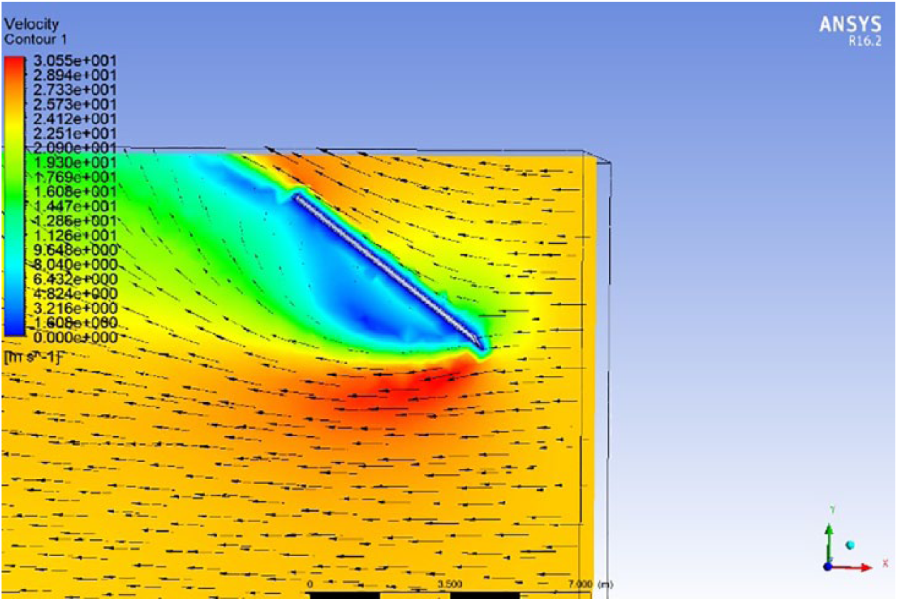
Velocity distribution (

Pressure distribution (
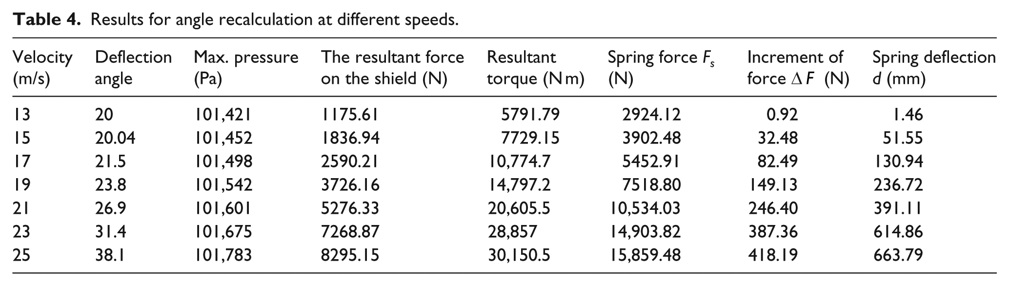
Table 4 shows shield parameters for varying wind speed values. From Table 4, the actual angles of shield yielding can be found for velocity speeds from 13 to 25 m/s in increments of 2 m/s. It is important to note that at 25 m/s, the deflection was equal to 663.79 mm, which is more than the maximally allowed deflection (635 mm). Hence, when deriving torque is 25 m/s, it is necessary to take into account the maximum allowed deflection (635 mm) which corresponds to 38.7° of shield yielding. To summarize, torque per degree of deflection can be revised in Table 5.
Results for angle recalculation at different speeds.
Torque values for corresponding angles of shield deflection.
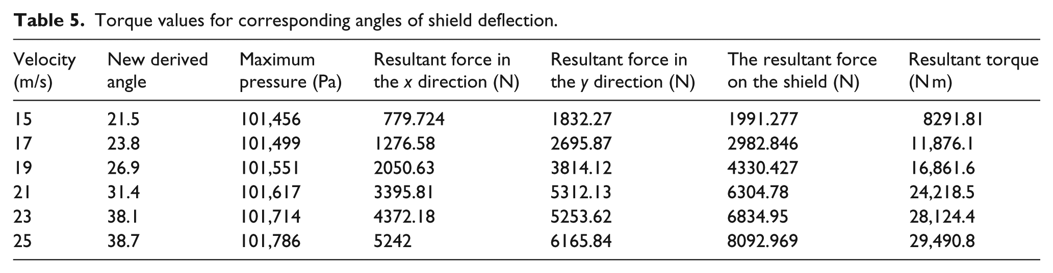
Figure 12 shows the graph of the change of torque per degree of shield deflection. It shows almost linear relations between these values.
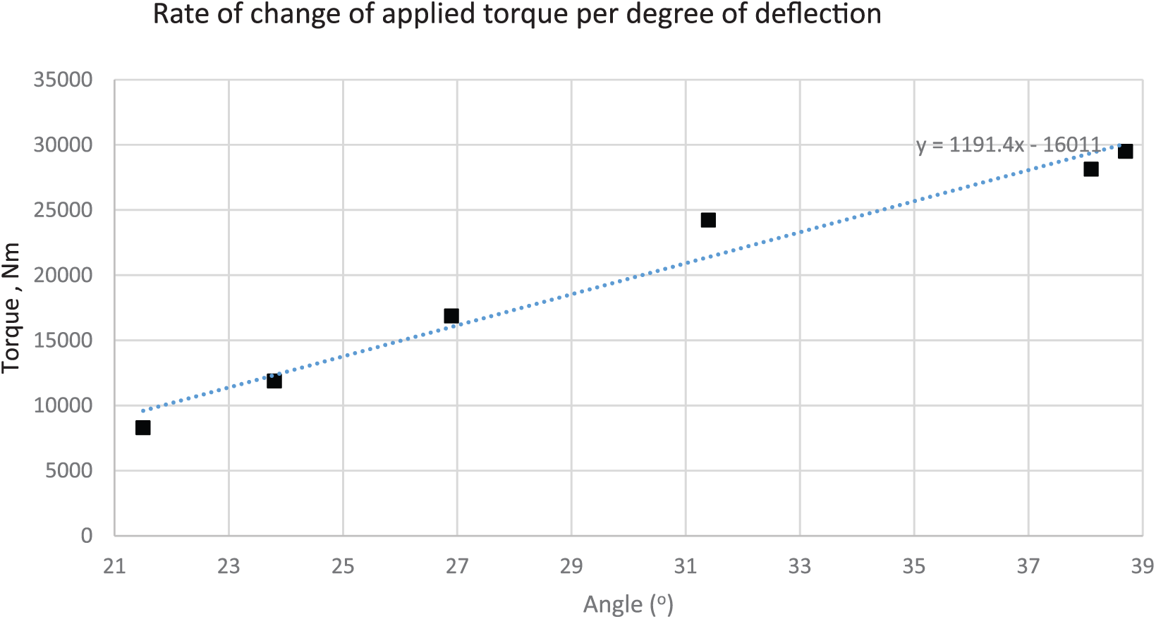
The graph for the rate of change of torque per degree of shield deflection.
Force analysis of the blades together with the shield and supporting springs
Since ANSYS only provides the pressure and force calculations at the stationary objects, it was decided to analyze and simulate the wind forces on the blades at different rotational angles. The rotor positions in the increments of 15° are shown in Figure 13. At these positions, wind patterns and pressure distribution were simulated at different wind speeds starting from 13 m/s and the corresponding deflections of the shield. As it was stated in the previous section, the selected set of springs allows the shield to stay undeformed up to wind speed of 13 m/s.

Illustration of the rotor blades positions for ANSYS simulation.
Mesh verification for rotor blades at 45° has shown that 877,000 mesh elements are enough to maintain reliable results. Figures 14 and 15 show samples of ANSYS simulation for
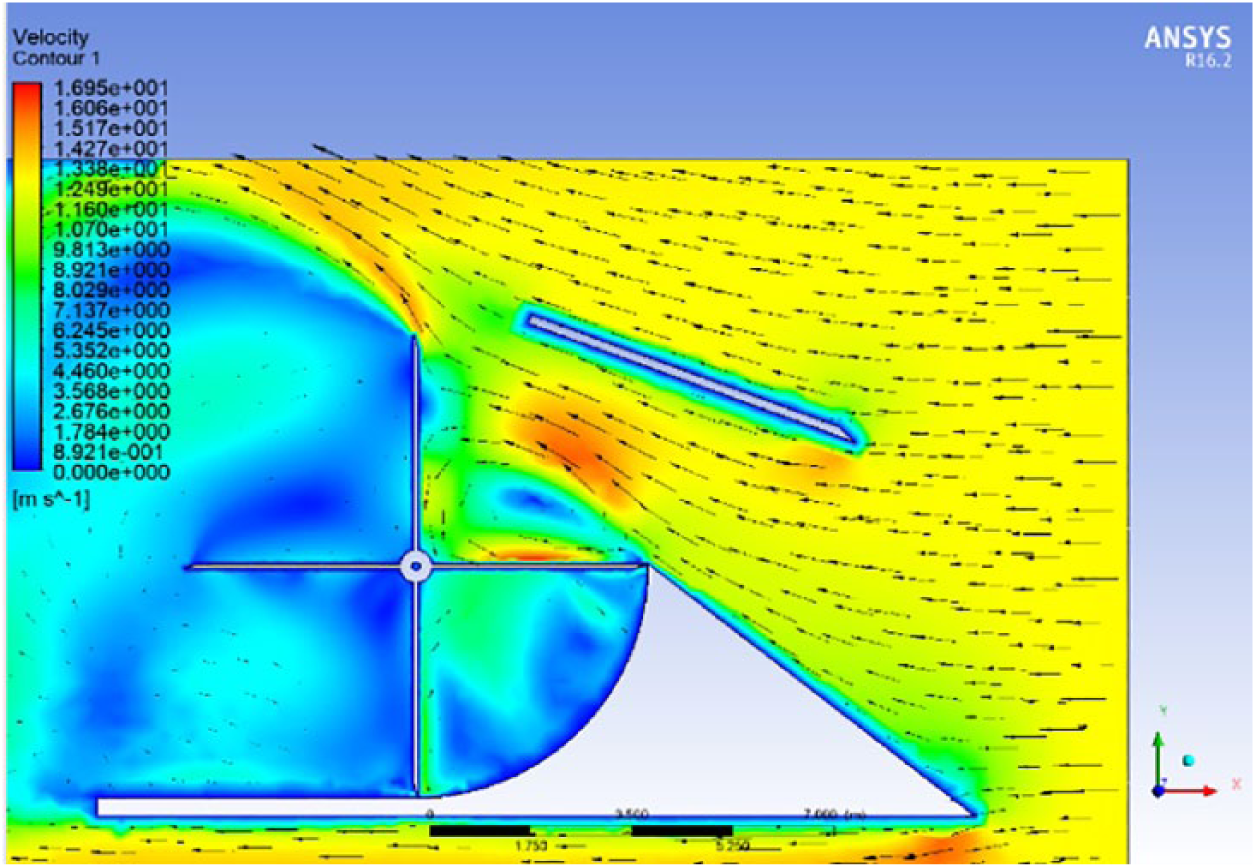
Velocity distribution (

Pressure distribution (
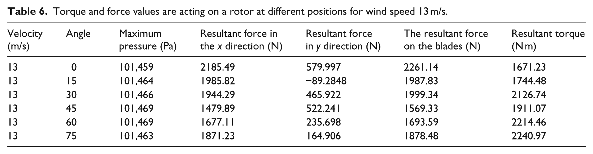
Similarly, velocity and pressure patterns were determined for all other positions of the rotor for every 15° when wind speed is 13 m/s (Figures 16 and 17). The numerical results of the simulations are summarized in Table 6. It shows how the driving torque values are changing with deflection of the shield.
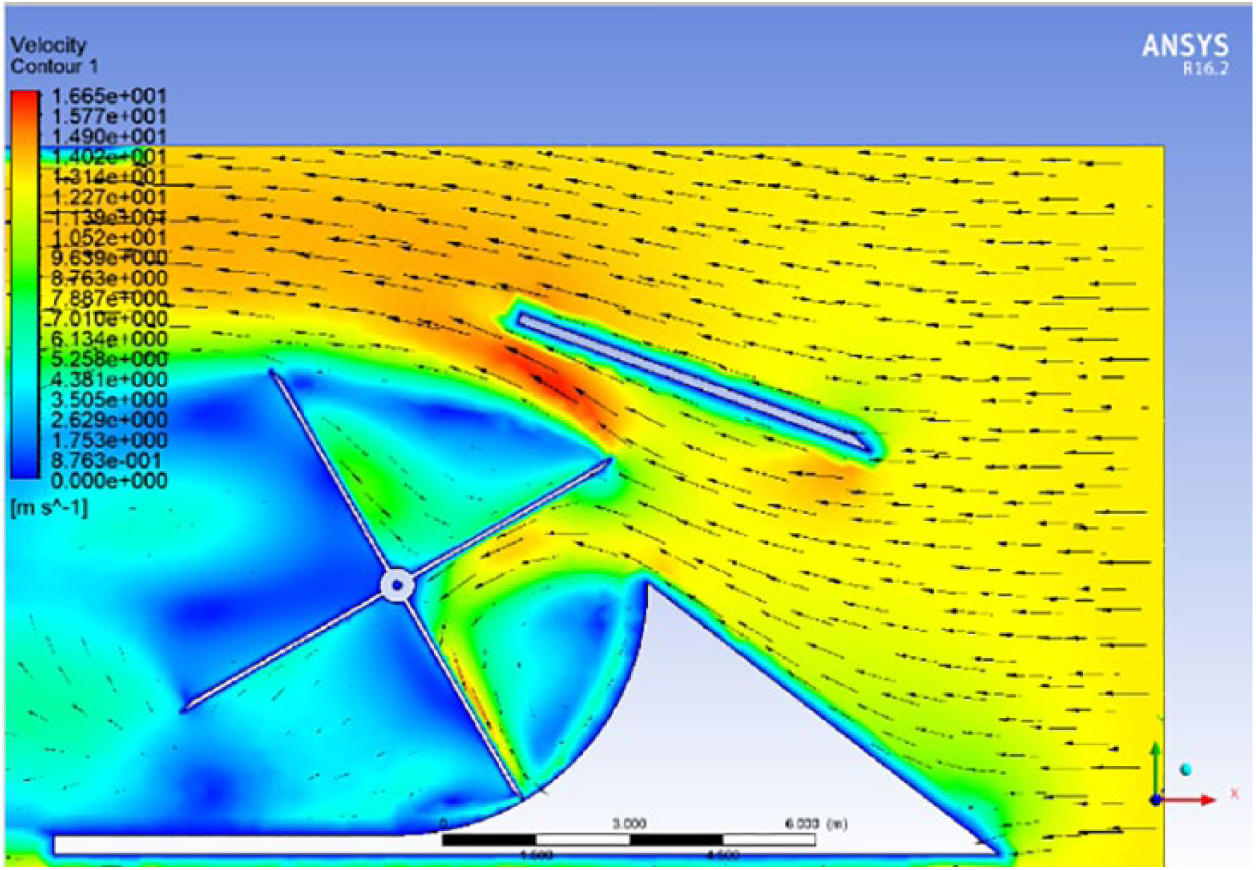
Velocity distribution (
Pressure distribution (
Torque and force values are acting on a rotor at different positions for wind speed 13 m/s.
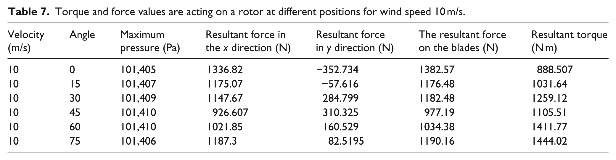
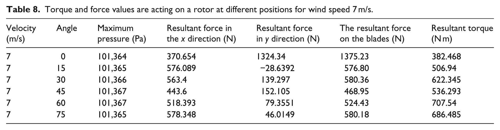
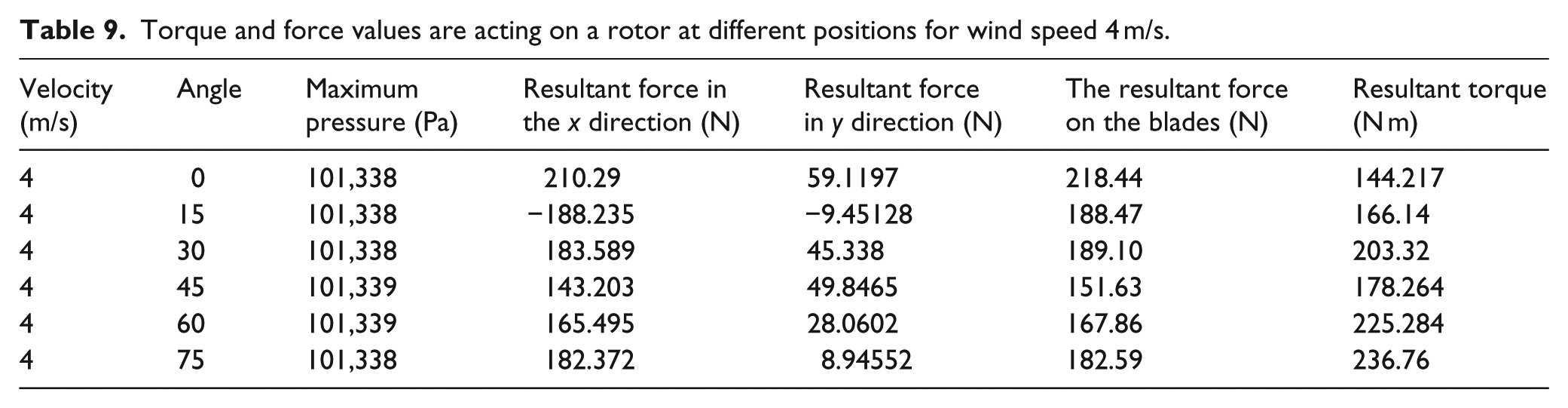
When wind speed is below 13 m/s, the generator works under normal conditions without danger of overspeeding. ANSYS speed and torque simulations for normal condition of the rotor operation are conducted for sample wind speeds of 10, 7, and 4 m/s. The acting on the blades’ force and torque results are shown in Tables 7–9.
Torque and force values are acting on a rotor at different positions for wind speed 10 m/s.
Torque and force values are acting on a rotor at different positions for wind speed 7 m/s.
Torque and force values are acting on a rotor at different positions for wind speed 4 m/s.
The tabular results are plotted in Figure 18; results can be summarized in a graph of torque values versus different angles of the rotor with respect to the horizontal plane. These results can be used for the dynamic simulation of shaft rotation to identify the speed of shaft rotation at different wind speed values. From Figure 18, it is quite noticeable that at 45° with respect to the horizontal plane, there is a steep drop of torque acting on the rotor at every speed of wind tested from 13 to 4 m/s, though the decrease becomes less significant at lower speeds.
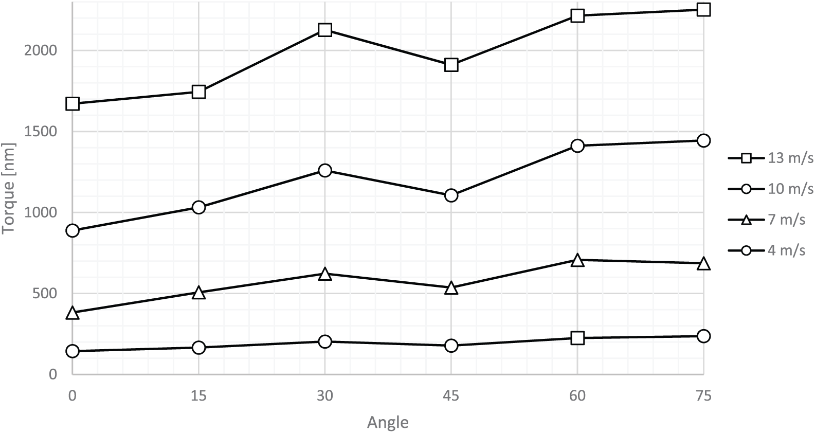
Driving torque versus rotor shaft angle at different wind speed values.
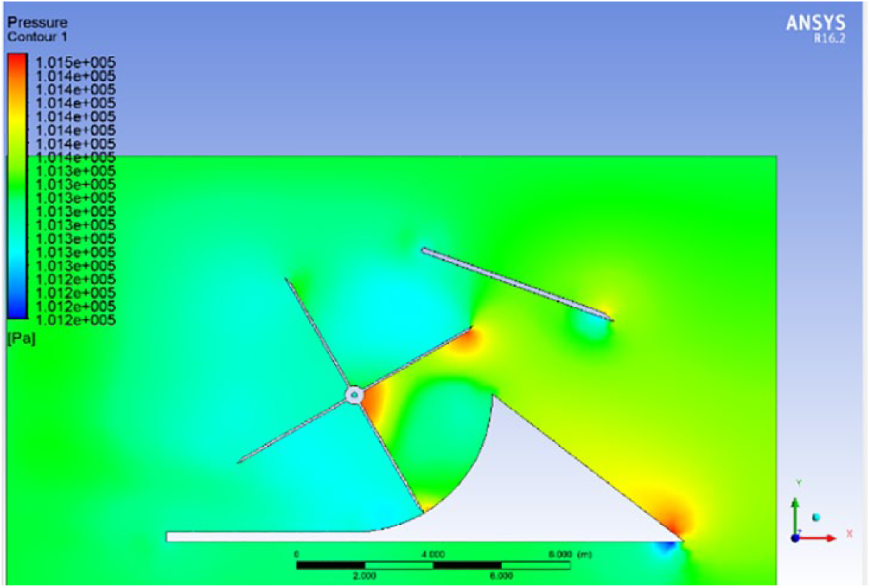
Similarly, the windshield effect at higher speeds from 13 up to 25 m/s can be investigated. The selected sets of springs (Table 5) allow only shield deflection up to 38.7° at 25 m/s. The ANSYS simulation analysis has been performed using the wind speeds from 15 to 25 m/s at different rotor blades angles. The analysis can help to identify to what extent the use of the shield is justified to overcome the critical driving torques on the shaft and prevent the damage of the rotor. Figures 19 and 20 show the samples of ANSYS simulation of pressure distribution for the rotor angles 0° and 30° for the wind speeds from 15 to 25 m/s in increments of 2 m/s.
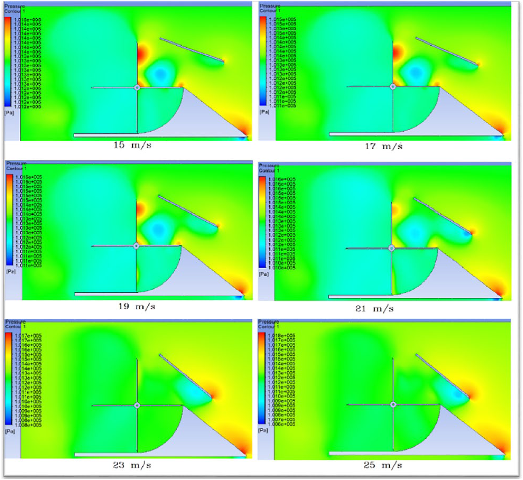
Pressure distribution (
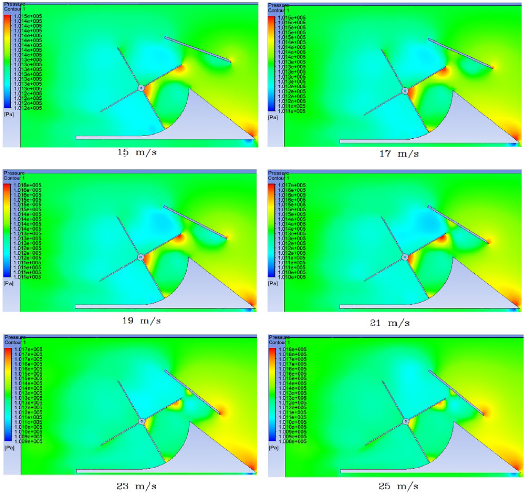
Pressure distribution (
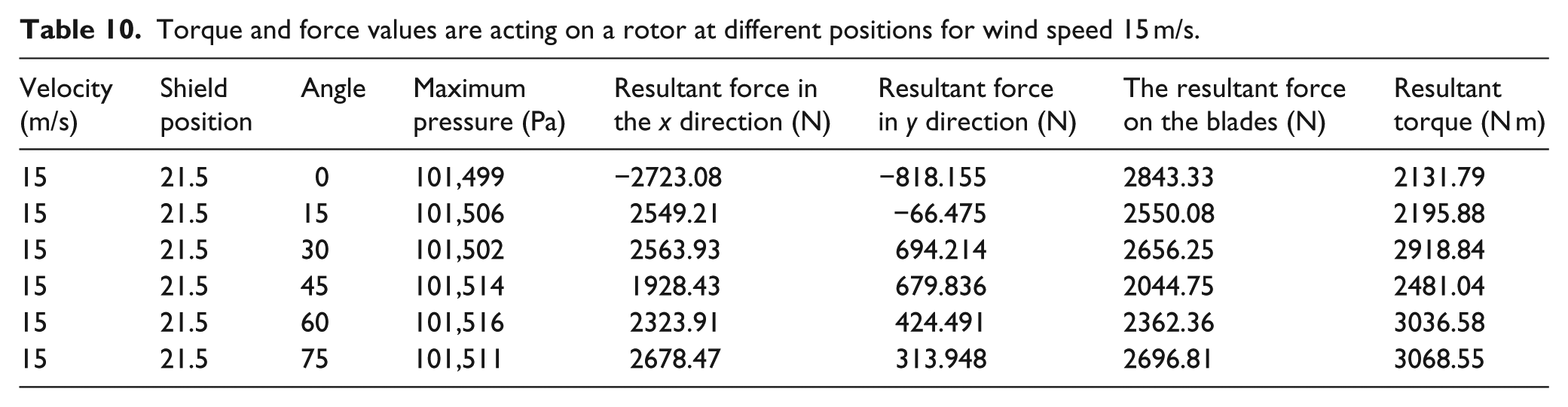
The numerical results of simulations for all positions of the rotor shaft, varying wind speed values (from 15 to 25 m/s) and the corresponding shield deflection angles (21.5°–39.6°) are shown in Tables 10–15.
Torque and force values are acting on a rotor at different positions for wind speed 15 m/s.
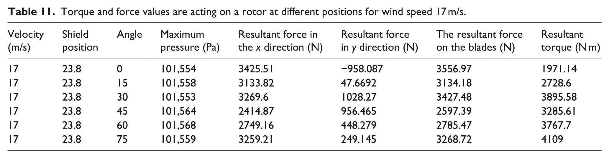
Torque and force values are acting on a rotor at different positions for wind speed 17 m/s.
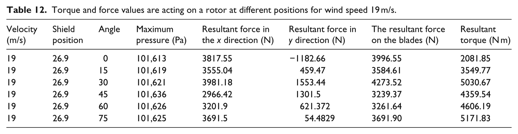
Torque and force values are acting on a rotor at different positions for wind speed 19 m/s.
Torque and force values are acting on a rotor at different positions for wind speed 21 m/s.

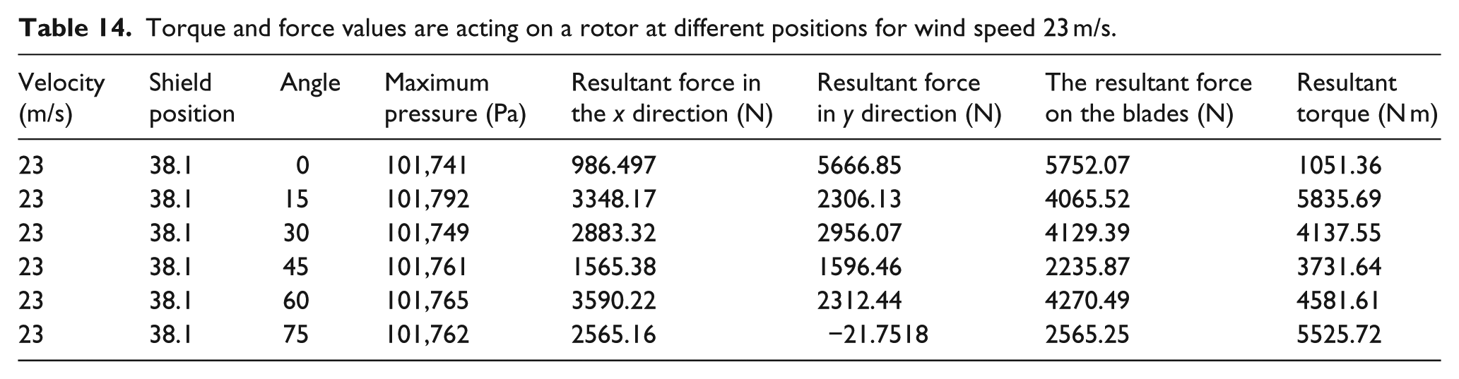
Torque and force values are acting on a rotor at different positions for wind speed 23 m/s.
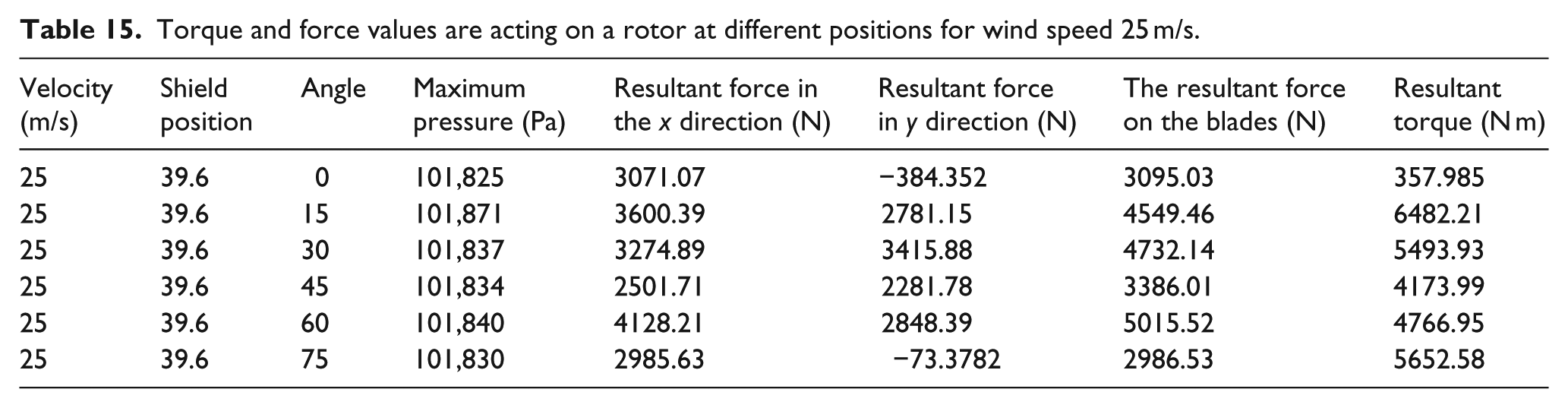
Torque and force values are acting on a rotor at different positions for wind speed 25 m/s.
The numerical results of the driving torque versus rotor angular position at various wind speed values are plotted in Figure 21.
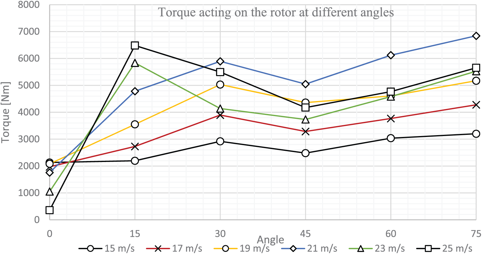
Driving torque versus rotor angular position at various wind speed values.
The graph in Figure 21 shows that with an increase of wind speed and due to the deflection of the shield, the torque value on the shaft tends to be reduced and maintained almost stable. The minor variation of the torque values is due to the accuracy of the simulation calculation. It justifies that the overall effect of the shield with attached springs is quite positive, and it can be used to prevent damage of the rotor due to excess of torques derived from high speeds.
Discussion
Comparative analysis of traditional three-blade HAWT versus the newly developed HASWT
HAWT is a lift-type device, with the blades rotating perpendicular to the direction of the wind at higher speeds than the actual wind speed. The airfoil shape of the blades allows creating a difference of pressures between upper and lower surfaces, resulting in a net force perpendicular to the direction of the wind. On the contrary, HASWT design is a drag-type device which rotates on a different principle. It supposes that the blades rotate along the direction of the wind. Hence, it may be stated that in a HSWT, wind tip speeds may be expected to be slower than in HAWT. In order to compare traditional horizontal wind turbine with three blades, it was decided to use the wind-affected areas of two blades in semi-exposed turbine design, as only two blades are constantly exposed to the wind. The effective area in the design excluding circular shaft area for our design was 14.92 m2 per one blade, doubled as 29.86 m2 of effective area. Thus, the effective area of a traditional blade has to be 9.95 m2 per each blade. These calculations resulted in a wind turbine with blades of 7 m radius. The patch conforming method using tetrahedrons allows reducing the computational time and is convenient for the complex shape of blades. A number of elements used in the analysis were approximately 1.7 million. The boundary conditions for the analysis were kept the same as for HSWT design. The ANSYS simulation of normal wind conditions (wind speeds from 7 to 13 m/s) for HAWT was conducted to compare the pressure patterns and corresponding torques, that is, for the range of speeds just before the shield for HASWT design starts deflecting. Mesh and computational domain for the selected HAWT wind generator are shown in Figures 22 and 23.

Mesh of a computational domain.

Boundary conditions for the computational domain.
As it was noted, boundary conditions for traditional HAWT were kept the same. The inlet wind surface distance and other parameters were identical with the simulations for HWST design. As an example, the pressure patterns on the blades due to the wind speed of 10 m/s are shown in Figure 24.
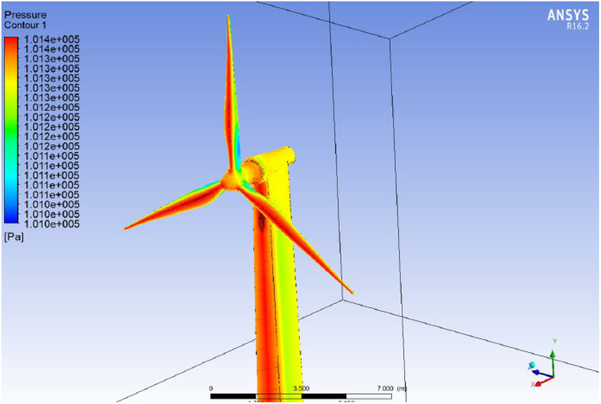
Pressure distribution on a HAWT for the wind speed of 10 m/s.
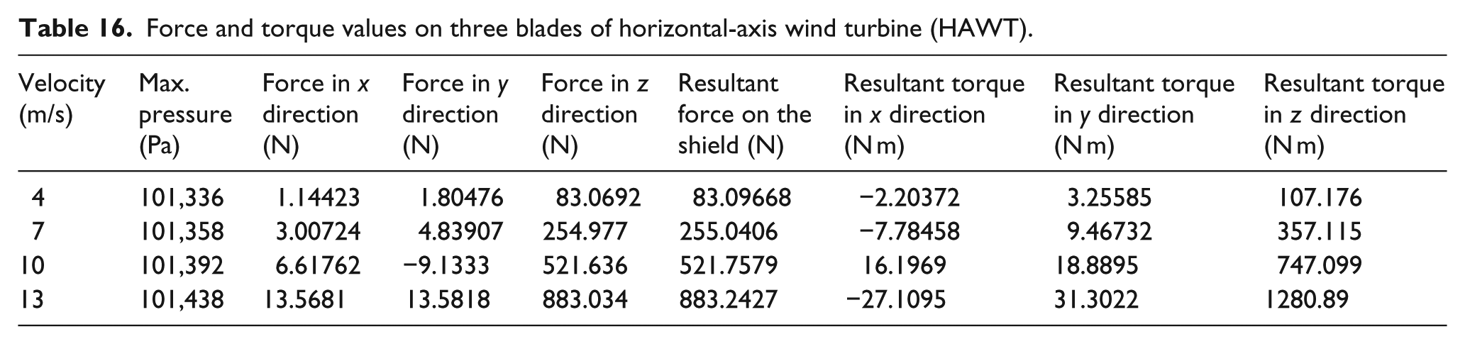
The numerical values of forces and torques on the three axes of the coordinate frame attached to the rotor shaft are shown in Table 16. The driving torque about Z axis which is parallel to the shaft axis is important because it will be responsible for the power generation. The torques around other axes or the resultant force along Z axis have a massive effect on the support tower and the bearings supporting shaft, and cause the loss of wind energy.
Force and torque values on three blades of horizontal-axis wind turbine (HAWT).
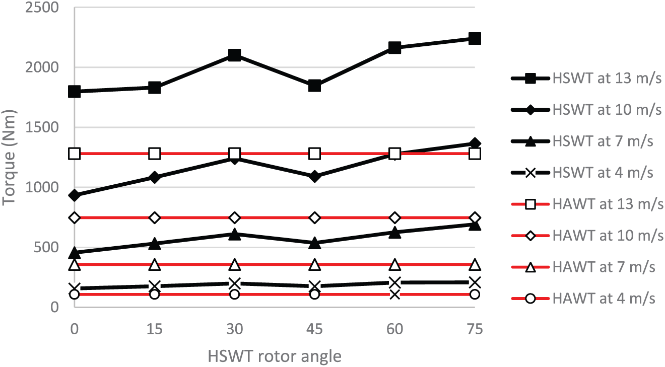
The graph in Figure 25 shows the plot of the driving torques around Z axis for HSAWT and HAWT versus the selected HASWT rotor angles. The increase in difference becomes more significant as the wind speed increases. It shows that the driving torque is higher for the newly developed HASWT as compared to traditional HAWT for all selected angles of the HAWT rotor.
Comparison of driving torques for HASWT design versus traditional HAWT design.
If we take the average torque derived from all the selected angles for HASWT design and compare it with a traditional wind turbine, there is a clear pattern that at higher speeds, the difference of torques increases in favour of HASWT design as is shown in Figure 26.

Comparison of torques on HASWT and HAWT.
Conclusion
The developed HASWT system can fully utilize the wind energy because the wind force applied on the blades generates only radial rotating torque on the shaft and no or very minimum components of the force are generated in the axial direction of the shaft. The vertically oriented tail of the platform like a rudder of the aeroplane enables the system to keep the rotor axis strictly perpendicular to the wind direction due to the balance of forces on both sides of the tail. This enables increasing the efficiency of wind power absorption. The important part of the design is the windshield that can automatically protect the generator shaft at extreme wind speeds from overspeeding and generating the power that is above the generator capabilities. The article presents the ANSYS-based force analysis of HASWT to demonstrate the potentials of this new wind turbine structure with the randomly selected rotor and blade sizes. The velocity patterns of the wind, as well as pressure distribution on the blades of HASWT rotor blades and the deflectable shield, have been derived based on the various speed of wind up to 25 m/s. The simulation results show the importance of shield when the wind speed exceeds 13 m/s in the prevention of the rotor shaft from overloading and overspeeding (Figure 21). For the normal operational speeds below 13 m/s, the article presents the results of ANSYS torque simulation for traditional three-blade HAWT generators with the same effective area subjected to the wind. The comparison of the driving torque results on both types of generators shows the advantage of the newly designed HASWT (Figure 26). The designed system has a compact design structure, is self-sustainable and does not require any power consumption. It can be easily installed on the flat roofs of high-rise buildings for the harvesting of wind energy. It is suitable for low and medium power generation, because for high power generation, it requires significantly longer and wider blade dimensions which could be a problem for their installation on the roof of high-rise buildings.
Footnotes
Declaration of conflicting interests
The author(s) declared no potential conflicts of interest with respect to the research, authorship, and/or publication of this article.
Funding
The author(s) received no financial support for the research, authorship, and/or publication of this article.