




Abstract
In this study, flutter frequency of two joined cantilever beams used for energy harvesting has been investigated and optimized. Since there is a strong connection between the output power of the harvester and the system flutter frequency, maximizing flutter frequency increases the output energy significantly. The governing equations are developed using Euler–Bernoulli beam theory, and series method as an analytical approach is used for the solution. The obtained results were compared with the previous investigations, and effects of change in geometrical parameters are studied. The maximum flutter frequency is obtained using shape optimization for the tail beam. It is concluded that the optimized shape of the tail beam with constant length and volume causes significant increase in the flutter frequency, which improves the output power.
Introduction
Considering the role of energy in the development of the global community, as well as taking into account environmental problems such as the climate change and increasing the need of humans for energy, the growth of renewable energy is one of the key purpose in the future of the energy industry. The use of renewable resources in addition to environmental and social impacts has provided an important opportunity to improve their economic indicators (Amri, 2017; Quaschning, 2016).
The high potential of wind energy is one of the most important options of the future of energy supply in the world. This sustainable energy accompanies with climate change and environmental conditions and is available globally in the planet and has much lower influence on the environment than other energy supply methods (Panwar et al., 2011). Reports show that energy consumption grew by 1% in 2016, and renewable energy production grew by only 14.1%, while more than half of that amount was provided by wind energy (British Petroleum, 2015).
In order to provide energy in countryside environments, wind turbines are continually being developed and optimized. Using turbines is the most important method of energy harvesting from the wind, which operate using the kinetic energy of the wind (Santangelo et al., 2016), and as a result, many wind farms are being developed around the world. But in urban environments, some restrictions such as dimensional issues, noise pollution, and safety have created many problems in designing these devices. These turbines require a high-energy flow to work; however, in common design, the transition speed at the end of the blade of these turbines is very high, which causes the noise pollution in the environment (Rostami and Armandei, 2017). Due to these constraints, more adaptive methods are needed to harvest energy in urban dense environments.
One of the solutions is employing piezoelectric energy harvesters. They have a simpler system than wind turbines, and their related systems, given their higher production potential, have better economic efficiency (Luo and Tong, 2015; Schoeftner and Buchberger, 2013; Tao et al., 2017). These harvesters have grown exponentially in recent years, and good conceptual models are emerging in this new field (for example, “piezoelectric flag (Orrego et al., 2017)” or “piezoelectric tree” (Dickson, 2008)).
One of the destructive phenomena in the context of the interaction between dynamic fluid and structure which we always try to control it is the flutter. The oscillation of the structure from hydro-/aeroelastic instability that is self-controlled and self-induced is flutter (Jung and Lee, 2011). Based on the previous studies Naudascher and Rockwell (1980, 2012), in general, two types of flutter may occur, Extraneously Induced Excitation (EIE) and Movement-Induced Excitation (MIE); the difference between these two models is in the method of inducing instability. In the EIE type, instability may occur as a result of being placed in the back of an immersed bluff body in the flow. Power of this type of harvester is proportional to the frequency, and at the best possible condition, flutter frequency is coordinated with the frequency of vortex shedding from the bluff body (McCarthy et al., 2016). If the frequency of vortex shedding is synchronized with the natural frequency of the structure, the strain rate increases due to the sudden increase in the amplitude of the oscillations. Previous research has been shown that the frequency of vortex shedding is proportional to Strouhal number, the free-stream velocity, and reverse of the bluff body dimension. However, based on Roshko (1954a, 1954b), for a certain band of the Reynolds number, empirical relations are introduced to describe the relationship between Strouhal and Reynolds numbers. Hobeck and Inman (2011) examined a conceptual model called “piezoelectric grass” in which piezoelectric components were arranged in vortex shedding from a bluff body, and at a speed of 11.5 m/s, this harvester was 1 mW in each base and created optimum turbulence conditions in order to maximize output power.
The other type of aeroelastic flutter is MIE. This behavior occurs for an immersed structure in a flow after a certain speed, known as the critical flutter speed, due to the change in the amount of damping, to a negative value, and results in a divergence deformation for the structure. This behavior is self-excited and self-sustaining (Theodorsen, 1979).
Studies and experiments by Connell and Yue (2007) describe three different types of states of MIE flutter. Depending on the length and stiffness of the beam and the flow velocity, MIE flutters may exhibit one of the following behaviors. (1) Fixed-point stability, in which the positive amount of the damping absorbs vibrations and eliminates fluctuations. (2) Chaotic flapping, during which there is a significant increase in the available drag force and the vibrating response band. (3) Limit-Cycle Oscillations (LCOs), where the range of oscillations is almost constant and shows the semi-sinusoidal behavior. These three different behaviors are depicted in Figure 1.

The displacement of the trailing edge versus the dimensionless time based on the different mass ratios studied in Connell and Yue (2007). Fixed point stability regime (–––), LCO regime (—), and chaotic flapping regime (———).
Piezoelectric harvesters are directly related to the strain created in the structure, and the maximum bending stress occurs in the LCO state Alben and Shelley (2008). The experiments and studies carried out by Mitcheson et al. (2008) are shown that the output power of these harvesters is proportional to the cubic frequency of oscillations and square of the vibration amplitude. As a result, with maximizing the frequency of oscillations, the output power can be increased significantly.
Experiments and investigations about the concept of a “piezoelectric tree” were continued by Li and Lipson (2009), during which an array of a polyvinylidene fluoride (PVDF) beam was connected to a triangular plate with a revolute hinge in the form of a “leaf and stalk” array. It came to the conclusion that the leaf expands the range of amplitude due to the effect of excess mass on the tip of the main beam and the addition of a higher surface to increase the surface pressure that makes the system more efficient at lower wind speeds. So, it has been found that the power of these harvester increases with this array. Geometry and leaf shape were studied in a similar system in experiments and studies (McCarthy et al., 2012). Bryant et al. (2011b) developed a linear theory to evaluate the effect of the hinge parameters on the critical flutter speed and frequency, which is valid in the range of small amplitude. In the following, a system was tested with a thin steel beam with two piezoelectric patch joints attached to it at the base, along with a rectangular plate, and concluded that adding the plate with revolute hinge to the base beam increased the power output (Bryant et al., 2011a). The influence of the hinge location on the frequency system was investigated by Deivasigamani et al. (2013). However, there is no study on the optimized shape of the second beam to increase the output power.
Two important parameters in determining the behavior of these types of flutter, which have significant effect on the power and efficiency of the harvester, are the critical flutter speed


If the mass ratio is large enough, the MIE flutters are usually a combination of first and second in vacuo modes (Hariri et al., 2009; Zhang et al., 2000). So, we need to define the dimensionless quantity of the mass ratio as follows

Depending on the mass ratio, the aerodynamic pressure may excite different bending modes (Yamaguchi et al., 1999):
For μ > 0.7, the flutter is closely similar to the second order in vacuo mode shapes, considering the traveling waves.
For 0.05 < μ < 0.7, the vibration modes deviated from the in vacuo mode shapes, and the mode shapes were close to third order.
For μ < 0.05, the mass ratio is insignificant, and the effects of friction and fluid mass are dominated.
Since the major assumption in equation (2) is that the aerodynamic pressure excites the lowest flexible bending mode, it is important to consider the mass ratio. In this study, the mass ratio is assumed to be μ > 0.7, and thus, it is expected that the flutter occurs in or close to the second oscillatory mode shape.
According to past studies, it is found that the maximum power is obtained in the lowest flexible bending mode (Alben and Shelley, 2008; Connell and Yue, 2007; Hobeck and Inman, 2011). By introducing a hinge at various positions and letting the beam to have variable thickness, the natural frequencies are changed, which cause the variation in the power output. The aim of this study is to find the optimum shape of two hinged beam with variable thickness and specific weight to obtain the maximum power.
In this study, the effects of changes in the geometry and shape of the second beam on the flutter frequency of joined beams are investigated. The obtained results are compared with previous studies and effects of geometrical parameters are further described. Finally, the optimized shape of the tail beam to have maximum value of output power is extracted.
Joined beams analysis
Displacements and strains
Consider a set of two joined isotropic beams, exposed on a wind with free-stream velocity of U, as shown in Figure 2. The x direction is the coordinate along the beam with the origin in the middle and L1 and L2 are the beam lengths. The first beam (piezoelectric section) has constant thickness and width (h0 and b0, respectively). The second beam is assumed to be tapered in both thickness and width directions varying from h1 to h2 and b1 to b2. η is the length parameter which specifies the hinge position and L is the total length of joined beams.
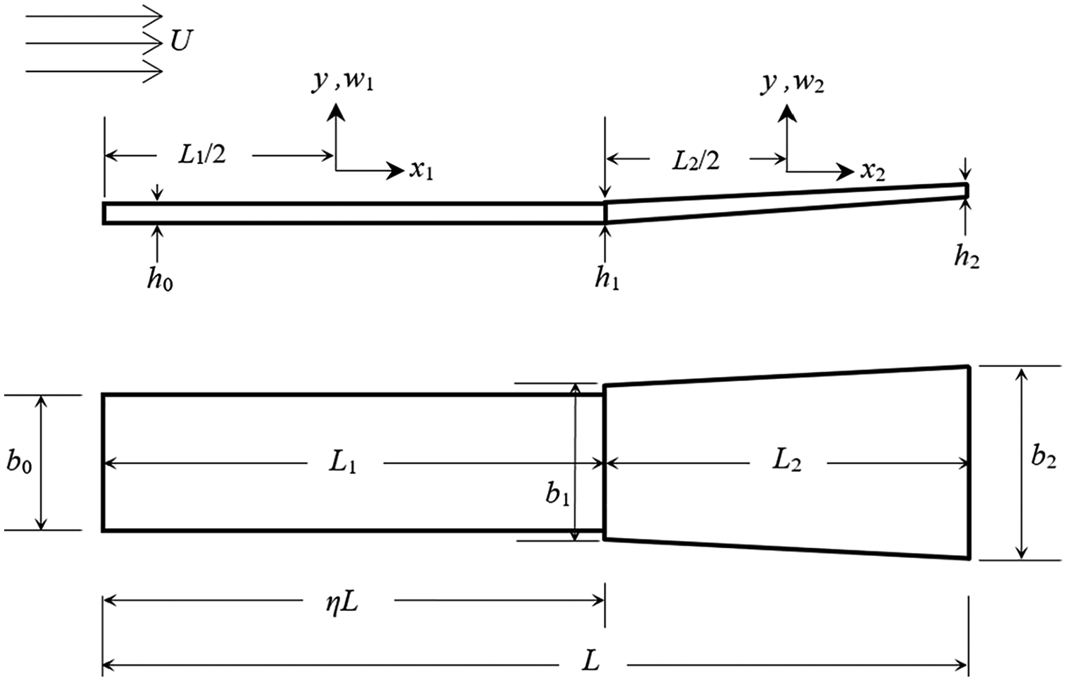
Geometry of two joined beams.
The governing equation for an isotropic beam with variable thickness is (Meirovitch, 1997)

where M is the mass of the beam. The structural rigidity (EI(x)) for the first beam is constant. In the second (tapered) beam, the structural rigidity can be calculated as

where

Solution procedure
The solution of equation (4) can be assumed as

and employing series solution in x direction we have (Shakouri and Kouchakzadeh, 2017)

where am are the coefficients that can be determined by recurrence relations obtained by substitution of equations (7) and (8) into equation (4) and matching the terms of same order in x

The Gi coefficients are
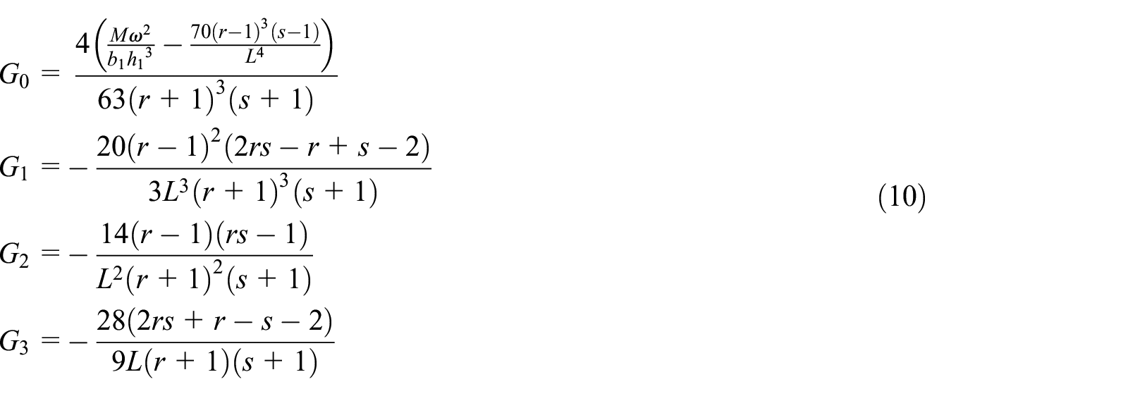
With these equations, one can evaluate all coefficients in w(x) with respect to a0, a1, a2, and a3. These four unknowns should be calculated from the boundary and hinge conditions. Thus, the general form of displacement function w(x) is in the form

Boundary and hinge conditions
The joined beam system is clamped at leading edge and free at trailing edge. Thus, the boundary and hinge conditions are described as
Clamped at x1 = −L1/2

Hinge conditions
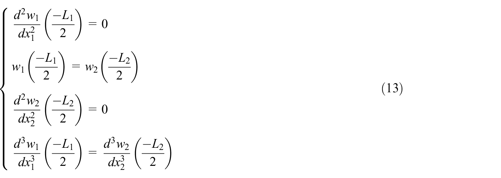
and free boundary at x2 = L2/2

where the subscripts “1” and “2” denote the beam number (see Figure 2). Finally, applying boundary and hinge conditions results in an eigenvalue problem as

where (
Numerical results and discussions
Comparative study
To evaluate the accuracy, the results of this study can be compared with previous investigations. Deivasigamani et al. (2013) investigated the flutter of joined beams with constant thickness and variable hinge position. The mechanical properties of the beams are (Deivasigamani et al., 2013)

Table 1 shows the comparison between the present results and those obtained by Deivasigamani et al. (2013). The nondimensional frequency parameter λi is defined as

Comparison between the results and previous works.
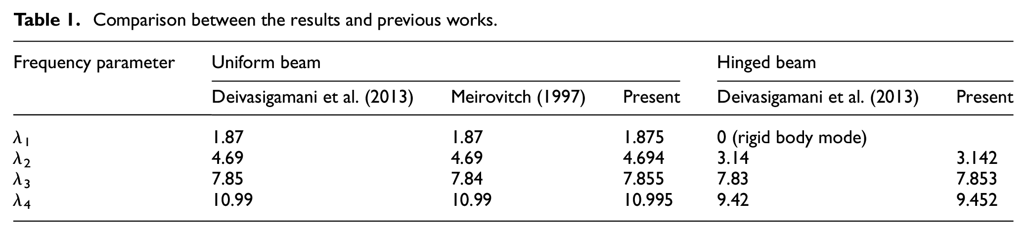
As seen, there is a good agreement between presented results and former investigations.
Figure 3 shows the comparison between natural frequencies with varying the hinge position (η = L1/(L1+L2)). The modal natural frequency ratio, Ri, is defined as (Deivasigamani et al., 2013)

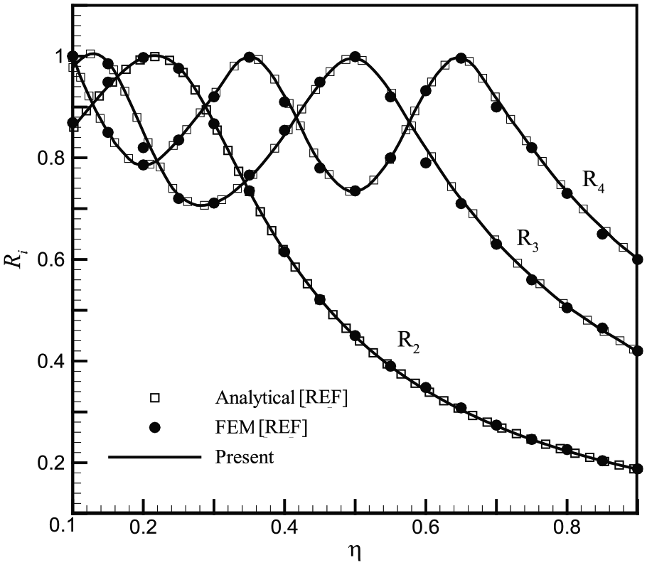
Comparison of results with finite element solving and analysis in Deivasigamani et al. (2013).
where
Parametric study
In the rest of this article, without restriction in generality of equations and solution procedure, it is assumed that the weight of joined beams is constant. This assumption is necessary to find the optimized shape of beams as will be seen in the following section.
Equating the volume of constant thickness beam with variable thickness one, and assuming h1 = h0, the relation between thickness and width ratios can be obtained as

According to past studies, in order to harvest energy from the fluttering oscillatory motion, the best mode shape for energy harvesting is the lowest flexible bending mode (Alben and Shelley, 2008; Connell and Yue, 2007; Hobeck and Inman, 2011). In this regard, we examine the ratio of R2 (the second mode shape) which is lowest bending shape mode of the system.
Figure 4 shows that the variations in the second mode shape frequency ratio of the system can be calculated according to the location of the hinge (η) and the thickness ratio (r). The initial value of h0 is 0.35 mm. It can be seen that for η < 0.5, the system flutter frequency (and output power) increases with increase in thickness ratio. For η > 0.5, the change in thickness ratio does not affect the frequency. It occurs because with increasing the η, the length of the second beam becomes smaller and the change in its thickness is more negligible.

Changes in the natural frequency ratio of the system with respect to different values of r in the range of variation of the hinge location in the second shape mode.
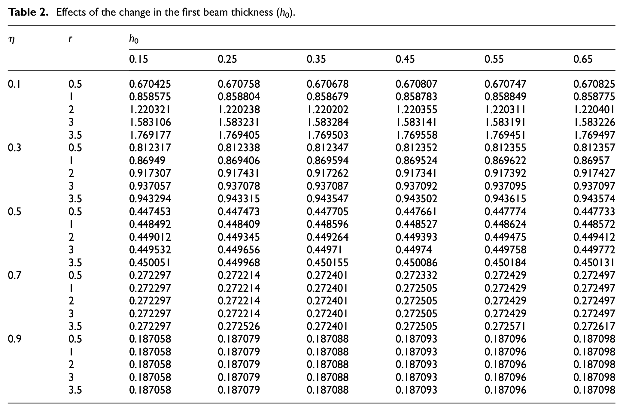
Effects of the change in the thickness of the first beam are shown in Table 2. As can be seen, increase in the initial value of the secondary beam thickness, which is equal to the thickness of the first beam, causes a negligible increase in the frequency of the system.
Effects of the change in the first beam thickness (h0).
Optimization procedure
In order to maximize the output power of the system, we need to know the effect of the flutter frequency on the output power. Various studies have been done on this subject, and Mitcheson et al. (2008) showed that the output power of the pick-ups is related to the flutter frequency cube as

where Pmax is the maximum power output and Y0 is the vibration amplitude. Although the output power is also related to the amplitude of the oscillations, the effect of the natural frequency is greater than that of the oscillation amplitude, and the effects of amplitude will be studied in the future work.
The maximization problem is defined as

maximize

constraints

By conducting this process, the best dimensions of the second beam to attain maximum fundamental frequency (R2) is achieved. Figure 5 shows the contour of the natural frequency ratios of system with respect to thickness ratio and hinge position. The properties are defined in equation (16).

Contour of frequency of lowest flexible bending mode with respect to hinge position and thickness ratio.
With regard to the changes in Figure 5, it is observed that in a certain range of hinge location (η), with increasing r, the frequency ratio reaches more than 1, which shows the improvement of frequency behavior as compared with the uniform beam. However, at higher η values, variation in the thickness ratio does not show any improvement in the frequency ratio. It should be noted that as η decreases, the length of the first beam decreases and the length of the secondary beam increases. Using smaller value of η and larger values of thickness ratio leads to the increase in frequency ratios of more than 90%. It means that the output power can be maximized with this optimized shape of the tail beam.
Conclusion
In this study, the variations in the tail beam geometry in an array of two joined beams are studied, and the optimized shape of this beam is obtained to have maximum output power. In order to optimize the shape, the volume and total length of the structure are assumed to be constant, and the changes in the flutter frequency of the structure with respect to hinge position, first beam thickness, and shape of the second beam have been studied. The main achievements of this study are as follows:
The increase in thickness ratio will increase the frequency when the first beam is smaller than the second one (i.e. η < 0.5).
The thickness of the first beam will not affect the frequency behavior of the system.
The optimized shape of the second beam leads to an increase in frequency of the structure of more than 90%.
It should be noted that optimizing the energy harvested from joined beams is a primary step to use them at an array of these structures in urban environments. Due to the high influence of the flutter frequency on the output power of such systems, the increase in the frequency of the flutter with the variation in the beam width in a fixed volume indicates the improvement of the output power of the system. Effects of the amplitude and critical flutter velocity should be further studied.
Footnotes
Declaration of conflicting interests
The author(s) declared no potential conflicts of interest with respect to the research, authorship, and/or publication of this article.
Funding
The author(s) received no financial support for the research, authorship, and/or publication of this article.
