



Abstract
This article proposes three new maximum power point tracking control schemes for permanent magnet synchronous generators in variable-speed wind energy conversion systems. Unlike previously control methods based on traditional voltage source fed equivalent circuit, a current source fed equivalent circuit is proposed where an efficient maximum power point tracking–based load angle control can simply be achieved. The three new control strategies are based on concurrent load angle control–rotor field–oriented method at desired speeds. Each strategy has its own load angle methodology. The first strategy applies constant flux control technique. The second one is based on keeping constant 90° torque angle (zero d-axis current control) method. Finally, the third strategy presents an optimum maximum power point tracking at unity power factor with achieving the favorite linear relationship between the generator stator current and optimum torque. A unified detailed phasor diagram is provided from which the phasor diagram for any of the aforementioned control techniques is produced. Mathematical analysis and MATLAB Simulink model results are presented for each control pattern. Effective validation for the proposed mathematical models is approved.
Keywords
Introduction
Variable-speed wind energy conversion systems (WECSs) are characterized by the maximum wind power extraction within its specified variable speed range (maximum power point tracking (MPPT) range) beyond which the power is kept constant. There are mainly two types of wind energy conversion generators (WECGs), one which uses doubly fed wound rotor induction generator (DFIG) with the stator windings connected to the grid and the rotor windings connected to a reduced power rating converter (about 25%) of the generator rated power. The converter used in Elsonbaty (1983), Elsonbaty and Holmes (1982, 1984), and Holmes and Elsonbaty (1984) is a cycloconverter while back-to-back converter is applied in Datta and Ranganathan (2002), Elsonbaty et al. (2015, 2016), and Mittal et al. (2010). This type of WECG offers smoother grid connection, high controllability, and reactive power compensation maximum power extraction. It is the most usually used generator in high-scale wind turbines. The other main type for low-to-medium-scale wind turbine is a permanent magnet synchronous generator (PMSG). PMSG and other variable-speed WECG types use full-scale power converters such as asynchronous and synchronous generators. Recently, a hybrid excitation synchronous machine (HESM) is proposed as a WECG (Ye et al., 2011). Flux switching permanent magnet generators (FSPMGs) have been used increasingly in direct-drive variable-speed wind turbines (Soleimani et al., 2019). The structure and basic principles of the direct-drive wind power system was studied, and mathematical model and simulation model were built (Tian et al., 2019). Variable frequency transformer (VFT) has emerged as a flexible AC link to transfer power in between asynchronous power grids (Bakhsh and Khatod, 2014). The permanent magnet synchronous motor (PMSM) now is becoming a popular choice in various industrial fields such as wind energy conversion systems for offshore application, and aerospace and electric vehicles (Nadia, 2003) because of its high efficiency, high power density, high torque density, no external excitation requirements, and full-scale power converters with high grid capability. Rezaei et al. (2019) proposed a model-based control system for a WECS using a direct-driven PMSG. A multidisciplinary design optimization (MDO) for PMSG as a WECG of direct-drive is proposed (Bazzo et al., 2016). Different MPPT strategies are applied in the literature, but two basic groups are most common. One of which is applying the Pm role which based on mechanical power–speed cube or torque–speed square relationship (Kot et al., 2013). The second group presents an iterative search for MPPT of wind turbine with the use of power and rotational speed and a feedback MPPT linearization controller based on optimization algorithms (Soufi et al., 2016). Analysis and performance evaluation of DFIG and PMSG based wind energy systems are carried out in Pidikiti and Ram Das (2019). The comparison aims to present the aspects of power quality (PQ) at the point of grid connection, harnessed power from both WECS at various wind velocities and converter rating. Mousa et al. (2019) proposed modified perturb and observe (MPO) MPPT algorithm for optimal power extraction of five-phase PMSG-based wind generation system. A double-closed-loop control strategy and simulation analysis of PMSG wind turbine with back-to-back converter is studied in Gong and Zou (2019). Two methods of sensor-less field-oriented control (FOC) to control the speed and torque of the PMSG were developed (Dao and Lee, 2019; Thayumanavan et al., 2014). In Thayumanavan et al. (2014), flux linkage and back EMF estimation methods are applied. Alternatively, the rotor angle is estimated from the stator currents instead of the back EMF or the stator flux components (Dao and Lee, 2019). Performance evaluation of an improved model predictive control with field oriented control is established by Zhang et al. (2017). Chang et al. (2019) proposed voltage-controlled PMSG-based wind turbines that can provide inertial frequency support. Whale optimization algorithm (WOA) for finding the optimal parameters of the conventional proportional–integral (PI) controllers for the PMSG in WECS is explained in Mohamed et al. (2019). The rotor angle and speed of PMSG are estimated indirectly based on the stator current vector using a proposed novel sensor-less control (Dao et al., 2018). Development and implementation of stand-alone PMSG-based distributed energy control system with variation in input and output parameters is established in rotor field–oriented (RFO) synchronously rotating reference frame (Mishra et al., 2019).
The main contribution of the work
The main objective of this article is to introduce the PMSG–current source fed equivalent circuit (CSFEC) as an efficient alternative to the traditionally used voltage source fed equivalent circuit (VSFEC). It offers much simpler and efficient control systems that achieve the application’s requirements especially for digital signal processing (DSP) control systems (Nadia et al., 2021). As stated in the later reference, both equivalent circuits of VSFEC and CSFEC result in the same conventional performance characteristics. However, the load angle has different physical meanings in both systems. In the presented system, the load angle,
The load angle in this article is explored for each of the three different proposed strategies for optimum and efficient WECS operation. This article structure is demonstrated such that section “CSFEC-RFO mathematical model” presents the mathematical model applying CSFEC of PMSG with RFO and its proposed phasor diagram. The first method of MPPT based on LAC for the induced back EMF control at constant flux control (CFL) operation is presented in section “MPPT-based LAC with RFO at CFL operation.” Second LAC that traces the maximum power point (MPP) at 90° maximum torque per ampere (MTPA) (zero d-axis current (ZDC)) is provided in section “MPPT-based LAC with RFO at ZDC operation.” Section “MPPT-based LAC with RFO at UPF operation (β − T UPF)” provides MPPT based on LAC for linear optimum torque-stator current at UPF operating pattern. The performance characteristics of the three proposed control patterns are compared and declared in section “Performance characteristics comparison for proposed strategies.” In section “Simulink results,” three control methods are modeled and simulated using software MATLAB simulation as compared by steady-state characteristics. Finally, conclusions are given in section “Conclusion.”
CSFEC-RFO mathematical model
Figure 1(a) and (b) depicts the per-phase CSFEC of PMSG and its decoupled d-q circuits. In case of RFO, the rotor PM flux

CSFEC and phasor diagram with RFO: (a) per-phase CSFEC, (b) CSFECs of PMSG, and (c) basic phasor diagram with RFO.
It is quite common that there is no damping in the PM synchronous machines, in which case the flux linkages are simply written as

The stator flux in all algorithms is given as



For Surface permanent magnet synchronous generator (SPMSG),

where

MPPT-based LAC with RFO at CFL operation
The optimum or maximum mechanical wind power and torque which should be tracked by the PMSG are characterized in terms of shaft speed by

Higher wind speed (higher generator shaft speed) results in higher back EMF leading to saturation and PM demagnetization. Thus, CFL value is to be constrained by the back EMF at each speed. The corresponding constructed phasor diagram is shown in Figure 2.
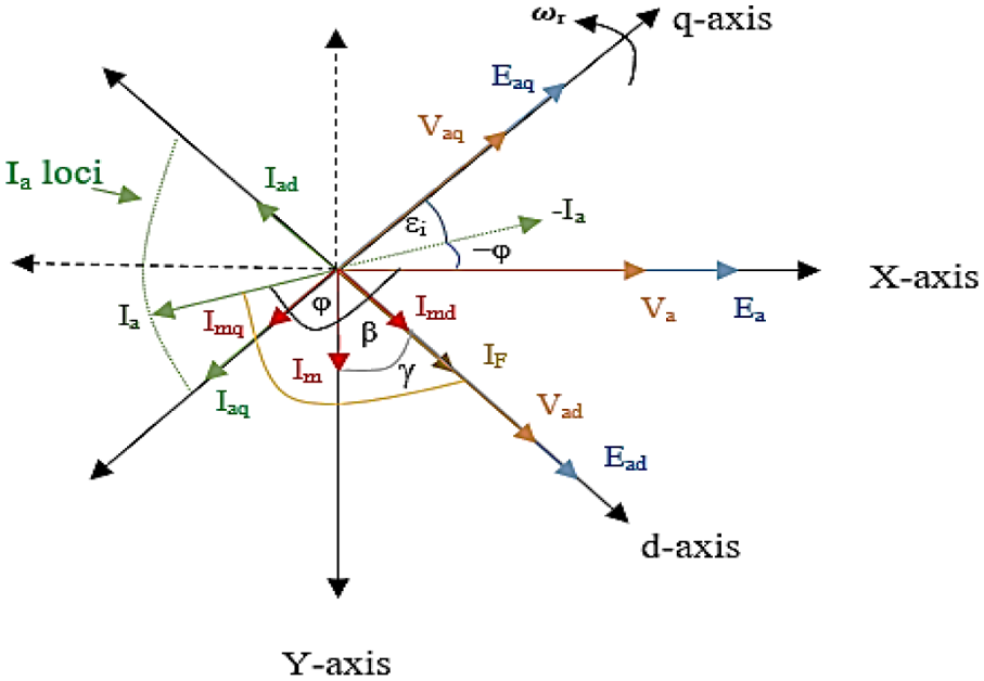
CFL-based LAC phasor diagram.
For CFL operation, the rated back EMF can be written as follows

The flux is actually determined with the stator winding supply frequency. Decoupled flux and torque control require that flux-producing current is aligned with the flux axis, while the torque-producing current is in an axis perpendicular to the flux axis as shown in the figure.
In the case of synchronous generator CSFEC, the stator current lies in the third or fourth quadrant depending on the PF angle type. While at lag PF, the PF angle is
Generally, the mechanical

From equations (8) and (9),
Applied the
MPPT-based LAC with RFO at ZDC operation
In this case, the two fields of stator and PM rotor must be kept orthogonal—in other words, the torque angle

where

And, the induced back EMF is given by equation (12)

Thus, EMF and voltage d-q components can easily be obtained at MPPT. The obtained characteristics are illustrated at the end of the next section for comparison purposes.
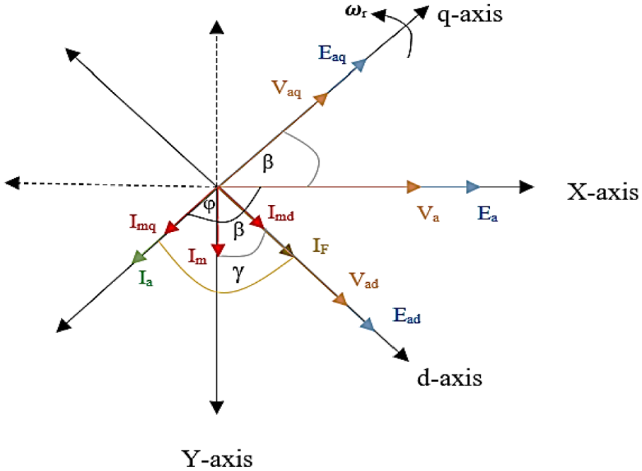
ZDC-based LAC phasor diagram.
MPPT-based LAC with RFO at UPF operation (β − T UPF)
The performance equations for UPF control are obtained from the phasor diagram shown in Figure 4. In UPF control methodology, the load angle

where the slop C can be calculated as follow

whereas load angle–torque

Applying equations (5), (6), (7), (12), (13), (14), and (15) with the common efficiency equation, all required MPPT steady-state performance characteristics are obtained as illustrated in the comparison given in the next section.
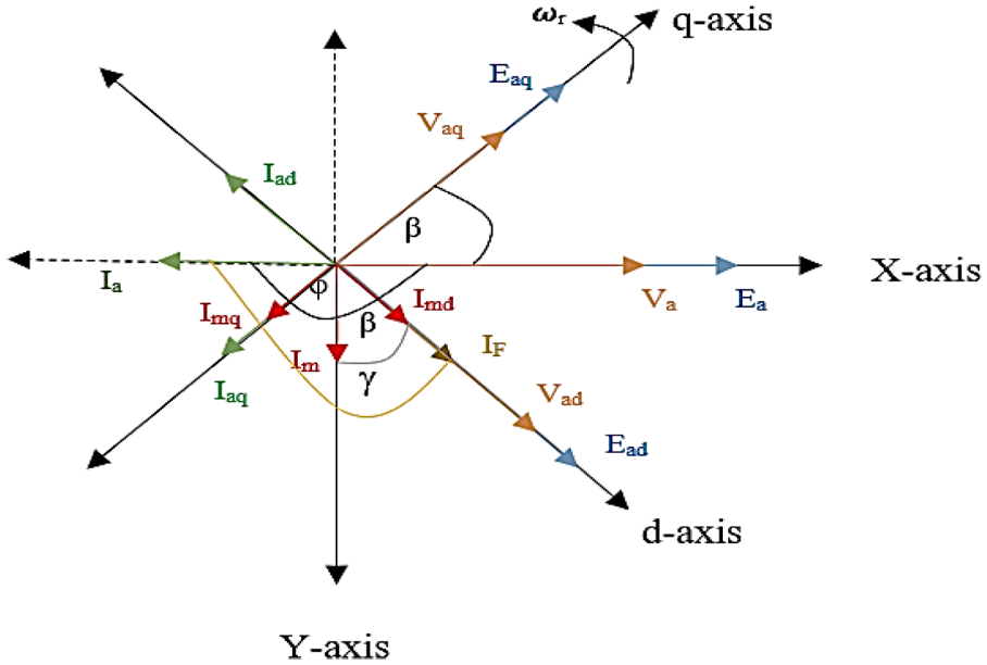
UPF-based
To ensure the accuracy of the proposed algorithms, two other different forms of


Performance characteristics comparison for proposed strategies
The performance characteristics of the three proposed models are compared in this section as given in Figures 5 to 17. Figure 5 illustrates load angle
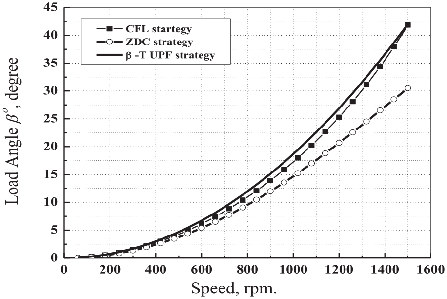
Load angle β (rotor position) versus speed at different proposed strategies.

Load angle β (rotor position) versus torque for different proposed strategies.

MPPT with different proposed strategies.
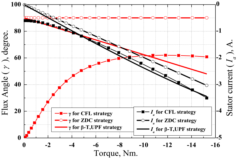
Stator current and flux angle versus torque at different proposed strategies.
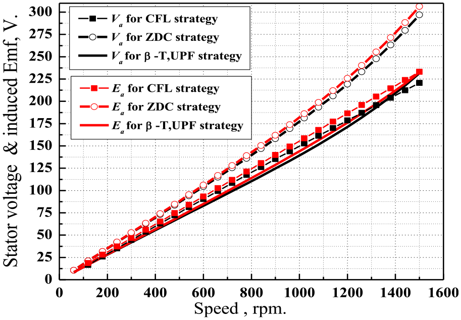
Stator voltage and induced EMF versus speed at different proposed strategies.
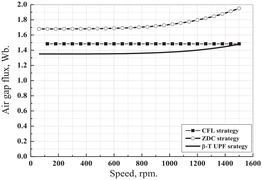
Air gap flux versus speed at different proposed strategies.

d-q stator current components versus speed for different proposed strategies.

d-q stator voltage components versus speed for different proposed strategies.

d-q induced EMF components with speed for different proposed strategies.
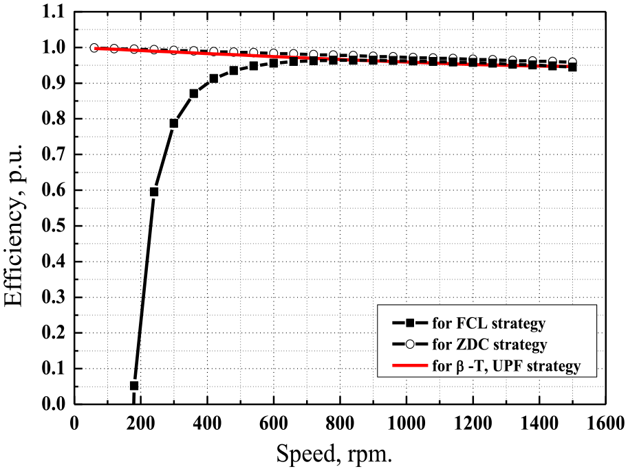
d-q induced EMF components versus speed for different proposed strategies.

Torque per ampere versus speed for different proposed strategies.
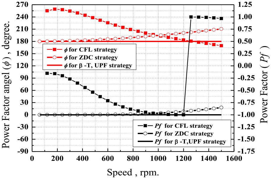
Power factor and power factor angle versus speed for different proposed strategies.
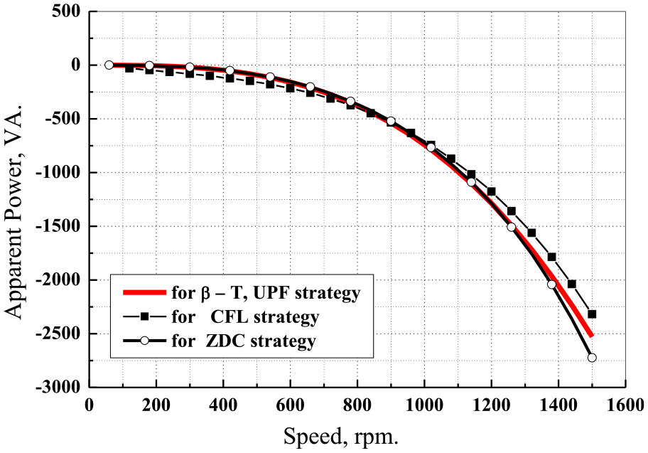
Apparent power versus speed for different proposed strategies.
Figure 8 depicts the stator current and flux angle versus torque. As expected, the resulted flux angle
Figure 9 depicts the stator voltage and induced EMF versus speed. As expected, the stator voltage and EMF with applied ZDC strategy are at much higher than rated values. UPF
Figure 10 illustrates the air gap flux for the three strategies from which aforementioned EMFs and voltages are resulted.
The stator flux component Id shown in Figure 11 approves the flux and EMF behavior as required to produce the same maximum torque at mostly the same torque component currents Iq. The stator direct current components have the direction of aiding the PM flux.
Figures 12 and 13 illustrate current, voltage, and EMF d-q components, respectively. Figure 14 shows that the efficiency of three strategies is almost the same; higher efficiency at speeds higher than 600 r/min. Lower speed results in lower efficiency for CFL strategy. Torque per amperes for the three proposed strategies are shown in Figure 15. ZDC strategy has the maximum constant TPA followod by CFL strategy but at higher speed while worse at low ones.
Three different power factors forms are obtained with ZDC strategy,
Simulink results
Simulation work is carried out using MATLAB and Simulink tools for each of the three proposed strategies. The represented simulation work in each category is carried out based on the following:
Performance characteristics verification by comparison of analytical results and Simulink results for the three proposed strategies in terms of speed.
Dynamic performance characteristics using Simulink model for each proposed strategy in terms of time. In order to evaluate the dynamic performance characteristics of the proposed strategies, several sets of simulations are conducted using MATLAB/SimPowerSystems toolbox. The Simulink model is composed of three main parts: PMSG model, PI controller, and proposed MPPT strategy as shown in Figure 18.
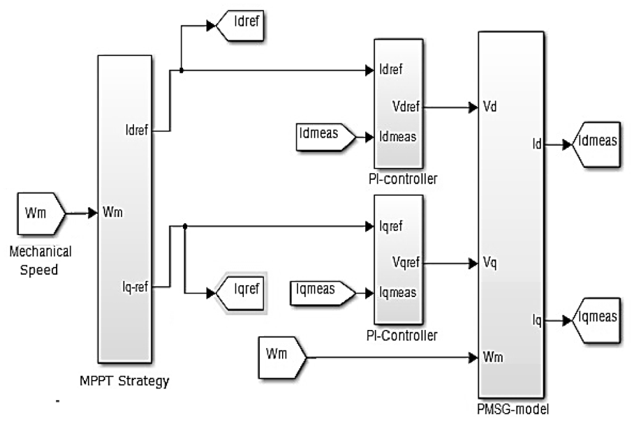
Simulink model of proposed system.
PI controller (designed using PI tuner in MATLAB–Simulink) is used to compare the reference d-q current and the measured d-q current from the d-q model of the synchronous machine, and PI controller output is the stator voltage reference d-q variables, where the d-q voltage equations for dynamic model are


The generated active power is calculated as

The developed mechanical power is calculated as given in equation (17).
Speed-based steady-state and dynamic characteristics comparison
Figures 19 to 23 illustrate steady-state and dynamic characteristics comparison of mechanical power, voltage, current, TPA, power factor with its angle, and stator voltage d-q components, respectivly.

Comparison of developed mechanical power steady-state and dynamic characteristics versus speed for different proposed strategies.
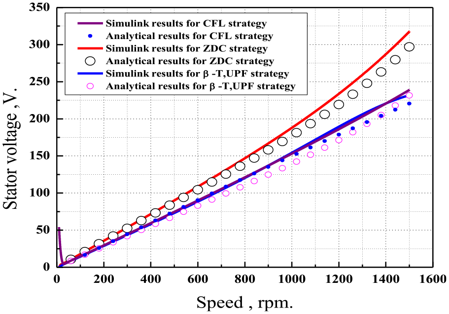
Comparison of stator voltage steady-state and dynamic characteristics versus speed for different proposed strategies.
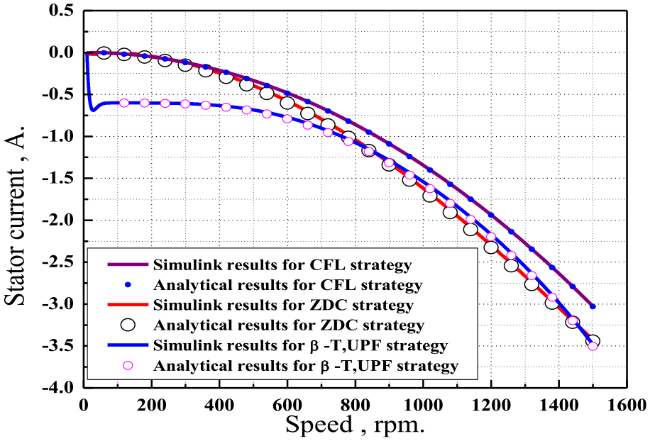
Comparison of stator current steady-state and dynamic characteristics versus speed for different proposed strategies.

Comparison of torque per ampere steady-state and dynamic characteristics versus speed for different proposed strategies.
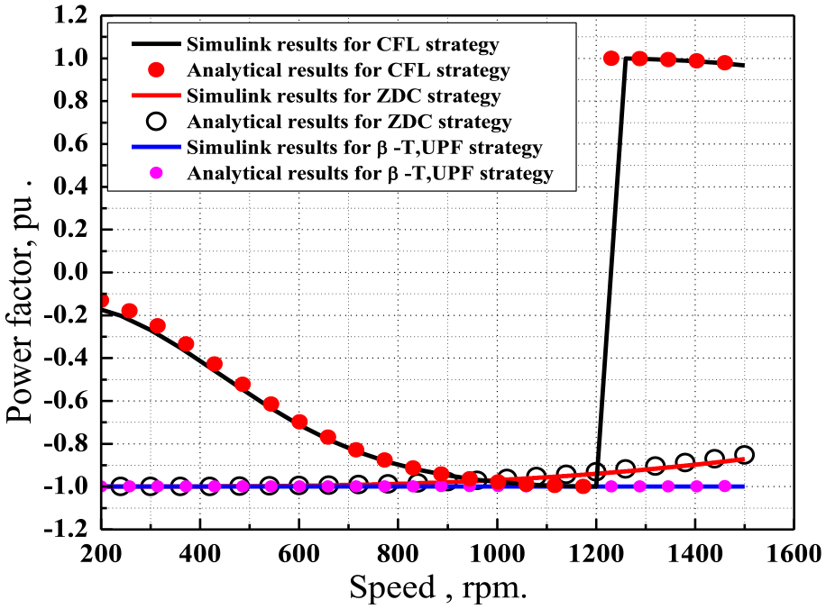
Comparison of power factor steady-state and dynamic characteristics versus speed for different proposed strategies.
Time-based steady-state and dynamic characteristics comparison
To investigate the dynamic performance characteristics of each strategy, Simulink model initially operates at 300 r/min, then the speed is changed every 2 s with 300 r/min increment until 1500 r/min is reached. Figures 24 to 26 illustrate a comparison between analytical results and Simulink results with each strategy for developed mechanical power, d-q stator current components, d-q stator voltage components, and stator voltage–current waveforms. It is clearly shown that there is a great acceptance between analytical results and Simulation results, which confirm the effectivness of the mathematical models.
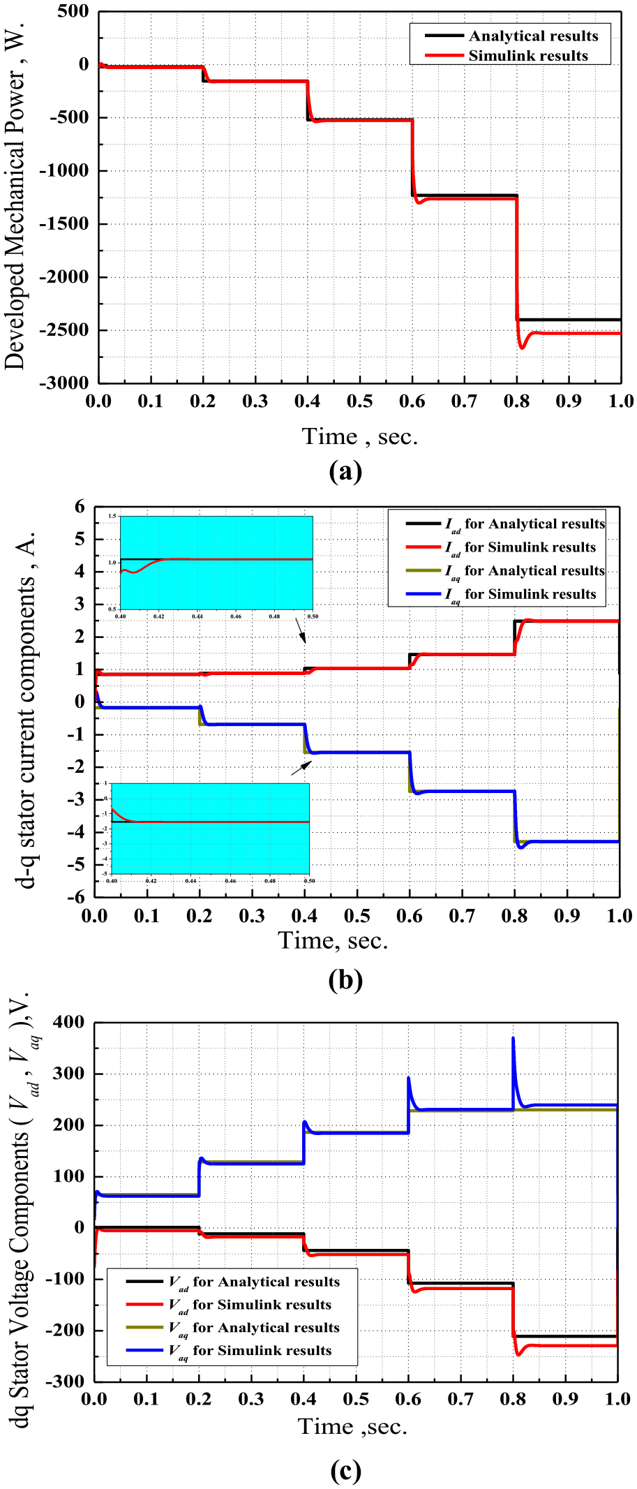
Comparison of analytical results and Simulink results for CFL strategy: (a) mechanical power, W; (b) stator current components, A; and (c) stator voltage components, V.

Comparison of analytical results and Simulink results for ZDC strategy: (a) mechanical power, W; (b) stator current components, A; and (c) stator voltage components, V.

Comparison of analytical results and Simulink results for β–T UPF strategy: (a) mechanical power, W; (b) stator current components, A; and (c) stator voltage components, V.
Conclusion
The most favorite vector control strategies of ZDC, CFL, and UPF are proposed by applying new techniques based on the CSFEC concurrent load angle–RFO for Permanent Magnet Synchronous Generator - Wind Turbine (PMSWG-WT). A detailed comparison is presented to evaluate the strengths and weaknesses of each strategy while MPPT. At low wind speed and power (around half rated power and 0.8 rated speed), ZDC has the advantages of maximum efficiency and TPA, UPF, and lowest Volt Ampere (VA). It cannot be applied at higher speeds to avoid de-magnetization risk and PM damage. In contrast, CFL control technique is efficient over higher than half speed with safe high wind energy extraction with high TPA, UPF, maximum efficiency, and lowest VA. CFL with LAC can be applied to control the reactive power. Furthermore, it assures stable operation due to the constant flux kept over the speed change. Finally, β–T UPF achieves a combination of the advantages of both of the aforementioned systems over the whole speed with wind MPPT. Furthermore, it is characterized by linear torque–stator current, which greatly simplifies the control process and improves the GSC PQ, which has not been achieved in any other research (to the author’s knowledge). Mathematical model with LAC function for each model is presented, and their performance characteristics are efficiently approved by the simulation results obtained from the MATLAB Simulink model.
Footnotes
Appendix 1
Appendix 2
The machine under study is 2.4-KVA, 220-V, 3.6-A, 50-Hz, four-pole, three-phase synchronous generator with the following parameters (Mohamed et al., 2012):
Stator per phase resistance Ra = 3.602 Ω.
Stator per phase synchronous reactance Xs = 51.304 Ω.
Stator per phase leakage reactance Xls = 11.2 Ω.
Declaration of conflicting interests
The author(s) declared no potential conflicts of interest with respect to the research, authorship, and/or publication of this article.
Funding
The author(s) received no financial support for the research, authorship, and/or publication of this article.
