



Abstract
This paper investigates a novel control strategy that enables hybrid excitation permanent magnet synchronous generator (HPMSG) to track the optimal extracted power of the modern wind turbine type (NASA-NSF). The proposed control mathematical model is based on two cases of variable speed—Maximum Power Point Tracking (MPPT) and variable speed—Constant Power Point Tracking (CPPT). The later one is specified for wind gust and higher than rated wind speed withstanding operation. The HPMSG generator quantitative performance characteristics are presented and validated through simulation for both steady and dynamics states. Simulation results prove the capability of the generator to operate correctly under load and speed variation over both MPPT and CPPT. The output voltage stays, in both cases, within the much lower limits that imposed by maximum values.
Keywords
Introduction
Wind turbine performance profile plays a vital role in the proficiency of wind energy extraction. HESMs have proven to be vital competitive machines for variable speed industrial and energy conversion applications. Mizuno et al. (1996) has shown that field control can easily be performed in Hybrid Excitation Permanent Magnet Synchronous Machine (HEPMSM) at a small excitation input. Hence, wide adoption of high efficiency multipurpose HEPMSM is expected in a variety of fields wherever field control is required. Thus, HEPMSMs with many different designs with bidirectional field control gained great attention in the field of electric vehicles as given in many literatures. Unidirectional field current control at high efficiency and enhanced EV performance was investigated in (Elsonbaty et al., 2020a, 2020b). Wardach et al. (2022) presented the design and operating principle of a hybrid-excited permanent magnet machine called HEPMa-SynRM which merges the advantages of permanent magnet and wound synchronous machines. The HEPMa-SynRM can achieve a large 1.5–1.55 control range of the field and over 50% increase in torque at lower currents compared to only 8% at higher currents. The compact rotor structure makes it well-suited for electric vehicle drives where high starting torque is necessary for dynamic acceleration. Flux-controllable machines classification on electrically excited, hybrid excited and memory machines is described and compared in Wang and Niu (2017). Different applications of Hybrid Excitation Permanent Magnet Synchronous Generators (HEPMSGs) such as Aircraft power generators (Louis, 2013; Tantawy et al., 2012) and for small hydropower plants (Kamiev et al., 2016) are investigated. A new topology for a high-speed hybrid excitation synchronous machine (HESM) was introduced in Su et al. (2024) to regulate the air-gap magnetic field of permanent magnet synchronous machines. Comprehensive analysis involving mathematical modeling and calculation of inductance parameters, voltage regulation, losses and efficiency was performed to evaluate the electromagnetic performance of the HESM design. Prototype testing successfully demonstrated the feasibility and effectiveness of the proposed HESM. Clearly, HEPMSG can show its challenge use in significantly varying applications where the operation conditions require fast air gap flux regulation for both enhancing and reducing flux.
The Most attractive application to this description is the wind energy conversion. Focusing on HPMSG for wind power generation, two different kinds of improving the generator wind power extraction and efficiency have been researched which are classified here to;
(i) HPMSG design and
(ii) HPMSG control to be integrated with wind turbines.
(i) Dealing with HPMSG design modeling, Dastani and Ardebili (2015) presented a design of an outer rotor generator with 24/16 doubly salient poles HPMSG by taking efficiency and power density as an objective function. In Amuhaya and Kamper (2015), a series Double Excited Synchronous Generator (DESG) concept is used with the rotor connected to the wind turbine via a slip coupler. A further design of doubly excited flux switching generator a stator containing armature coils, PMs and excitation coils is presented in Cherif et al. (2019) for small-scale wind turbines in rural and/or urban context. Wang et al. (2020) and Zhao et al. (2020) investigated a relieving-DC-saturation for HPMSG in wind power conversion, a novel winding-switching of a Hybrid Excited Reluctance Machine (HERM) strategy is investigated in Jiang et al. (2021). It may be noticed that, although Wang et al.’s (2020) investigation was for wind power conversion; however, the obtained torque-speed characteristics reviles for EV application as well. An experimental work of an alternative wind energy generator, particularly designed is investigated by Bouras et al. (2020). The generator is similar to an Electrically Excited Synchronous Generator (EESG) mounted upside-down. A high voltage hybrid generator (HG) and conversion system for wind turbine applications are presented in Beik and Schofield (2018).
(ii) Due to development of wind turbines and power electronic technologies may introduces the HPMSG control modeling for wind applications to be more efficient, highly qualified in terms of turbine’s integration and more economically as compared with structural control. A control strategy of Hybrid Excited Synchronous Machine (HESM) for wind applications was proposed to achieve MPPT and stabilizes the DC link voltage as given in Ye et al. (2011). Chakir et al. (2015) presented an output feedback MPPT for wind turbine equipped with a HESG to achieve wind turbine speed and HESG timing angle control for MPPT. Hlioui et al. (2022) demonstrated that, although the interesting and topicality of specified mentioned literatures in renewable energy, quantitative figures, as these available for automotive drives, concerning the usage of the electric machines in the (Torque, Speed) or the (Power, Speed) planes, are not accessible in scientific and technical literatures. The presented paper takes this value comment into account to achieve these requirements.
The research contributes valuable insights into enhancing wind energy extraction through advanced HPMSG control strategies. Belkacem et al. (2022) proposed HEPMSGs for wind energy conversion indicating the significance of field control for optimal performance. The proposed control strategy successfully tracks power and torque under varying conditions, showcasing its effectiveness for wind turbine applications. Gajewski and Pieńkowski (2021) emphasized the importance of efficient HPMSG design and control integration with wind turbines for improved power extraction and efficiency. By focusing on Maximum Power Point Tracking (MPPT) and Constant Power Point Tracking (CPPT), the research highlights the versatility and applicability of the control strategy. Jiang et al. (2023) proposed control strategy for HPMSG in wind energy conversion systems effectively tracks power and torque under varying conditions. (Elymany et al., 2024) presented two novel meta-heuristic optimization algorithms, the Zebra Optimization Algorithm (ZOA) and the Artificial Gorilla Troop Optimization (AGTO), for maximizing the output power from wind energy conversion systems (WECS) employing hybrid excited synchronous generators (HESGs). The proposed algorithms aimed to optimize the HESG operation by extracting maximum power from the wind while minimizing the power losses associated with the hybrid permanent magnet synchronous generator (HPMSG). A comparative performance evaluation of ZOA and AGTO was conducted based on computational time and solution accuracy. The ZOA exhibited superior performance compared to AGTO, providing more accurate solutions within a shorter computational time. The proposed algorithms can be valuable tools for optimizing the operation of HESG-based WECS, contributing to improved efficiency. This paper proposes a novel HPMSG control topology to efficiently match with the modern variable pitch angle wind turbine (VPAWT) characteristics explained in section II.
Wind turbine’s operational characteristics classification
Based on the pitch control mechanisms, the wind turbines can be classified as:
(a) Older fixed pitch angle wind turbines (FPAWT).
(b) Modern variable pitch angle wind turbines (VPAWT).
As shown in Figure 1, FPAWT is characterizes by power/speed3 which (MPPT) within ω ci < w > ωr. In addition to MPPT, if the wind exceeds its nominal value, the pitch angle will vary in such away the power coefficient Cp and tip-speed ratio decrease to new values depending on the wind speed to maintain the turbine extracted power constant at its rated value with limited wind velocity. Figure 1(b) illustrates the first presented modern VPWT system (NASA - NSF) coupled with a cycloconverter driven DFIG for transducing the captured wind power to the Grid (Holmes and Elsonbaty, 1984).

Wind turbines extracted power speed characteristics: (a) FPAWT-MPPT and (b) modern VPAWT-MPPT & CPPT (NASA- NSF) (Holmes and Elsonbaty, 1984).
Maximum power limits concept
Maximum power control has two parts, the maximum power point tracking (MPPT) and the constant rated power tracking (CPPT). The control strategy is proposed for both flux strengthen weakening regions by linearity field current—speed characteristics. On the other hand, CPPT strategy includes two parts, the constant power district judge and the constant power district control strategy. The constant power district judge is the premise of CPPT control. When the rotation speed exceeds the generator’s rated rotation speed, the output must consider the safety request of both current and voltage constraints as judge criteria. The applied system consists of consequent-pole HE machine (Figure 2) driven by Horizontal axis-variable pitch control angle wind turbine (NASA-VPAWT) whose power–speed characteristics are given in Figure 1(b). Both of DC/DC and AC/DC converters are connected to the wound field winding the three phase armature winding respectively as shown in Figure 17(a).

Consequent-pole HE machine: (a) construction (Elsonbaty et al., 2020a, 2020b) and (b) flux paralleling concept (Louis, 2013).
Due to its cost-effectiveness consequent pole HPMSG is considered in this paper as shown in Figure 2 for both structure and flux paralleling concepts.
Investigated control schemes
The control schemes in this paper are based on generator 0 day-axis current (zdc) and Wound Field (WF) excitation current at variable speeds for modern wind turbine integration as given below.
HPMSG mathematical modeling concepts
The proposed mathematical model of a HPMSG in d-q synchronously rotating axis is based on d-q-equivalent circuit of Figure 3 and declared by a corresponding phasor diagram of Figure 4 respectively.

HPMSG equivalent circuit in d-q frame.

HPMSG phasor diagram with ZDC.
The physical (natural) equivalent circuit prescribed parameters are defined by equations (1)–(6).




A load dependent Park’s d-q vector diagram for HPMSG with zero
The stator d-axis—WF current linkage flux and field circuit voltage are:


where
Proposed HPMSG control strategy for modern wind turbine integration
The maximum power operation up to modern wind turbine (MWT) safety operating speed can be achieved with optimal torque control according to MPPT and CPPT depicted in Figure 1. Thus, the flux regulating process are decomposed here into two steps:
(a) MPPT and
(b) CPPT
(a) In the first step of MPPT, the power is proportional to cubic speed, combination of the two excitation sources is applied to increase the torque, reduce the required armature current, increase the efficiency, and consequently reduce converter costs. With neglecting the gear ratio and mechanical speed losses for simplicity, the turbine shaft mechanical speed ωT can be easily converted to the generator mechanical and electrical speeds ωr and ωS respectively. At generator rated speed and rated power, the coefficient Ko can be determined. Consequently, both of PMO and the shaft torque


With proposed control strategy, the WF current is linearly increases with the generator speed and so the excitation flux (

Referring to Figure 4, the load angle of the HPMSG is obtained as;

Hence the generator power factor angle

The remaining required data as conventionally known with ZDC are:






(b) Conversely, in the second step of CPPT, the reached rated WF current at rated speed starts to decrease with same linear–speed performance in order to decrease the air gap flux in such a way to maintain the power constant at its rated value. The same aforementioned equations are applied but with constant rated power in equations (9) and (10).
HPMSG—Modern wind turbine performance characteristics
The obtained performance characteristics of the presented system are depicted in Figures 5–16. As shown in Figure 5, PMO and Tm are the optimal maximum power and its corresponding torque. To validate the applied algorithms; physical d-q of Pd1 and




Where; Eq, Ed, and Ea are given by (26).

Tracked MPP, CPP with shaft torque versus speed.

HPMSG induced EMFs and stator voltages components versus speed.

AC and DC stator current components versus speed.

HPMSG cupper losses versus speed.

PMSG output, reactive, and input powers versus speed.

HPMSG efficiency and power factor versus speed.

Torque, power factor angles, and WF current versus speed.

Output stator voltage and induced EMF versus WF current.

Torque per ampere versus speed.

HPMSG different flux components and HR versus WF current.
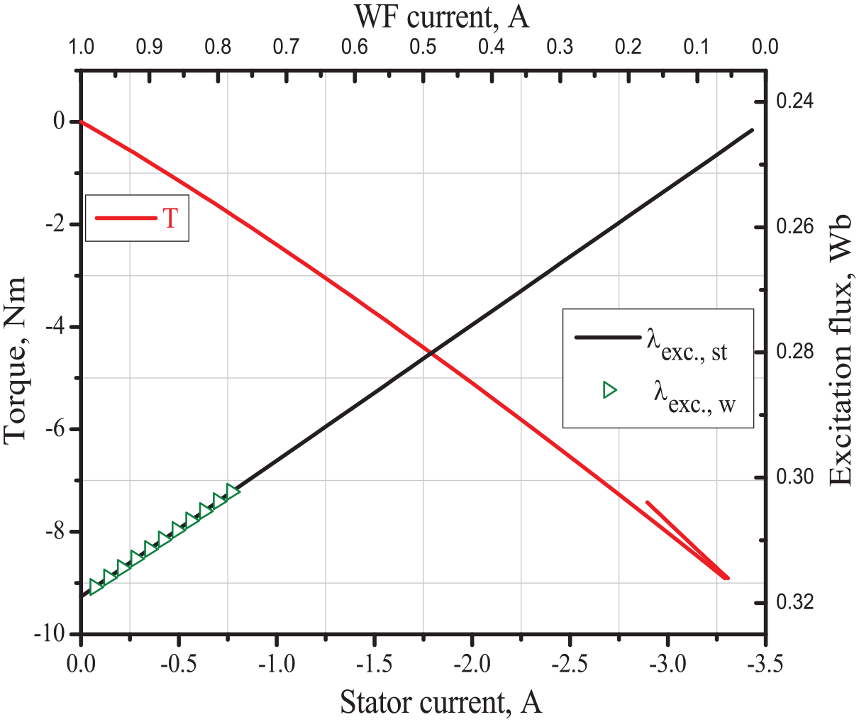
Torque–stator current characteristic (Left-Bottom axis) and d-axis flux (excitation flux)/WF excitation characteristic linearity (Top-Right axis).

Stator’s EMF, voltage, and load angles versus speed.
Figure 6 demonstrates two physical EMFs

AC, DC stator current components and WF current with speed variation are illustrated in Figure 7. With wind gust occurrence, the turbine accelerates beyond the HPMSG field strengthen MPPT at rated speed and rated WF current (1A). The field then starts weakening in linearity with the current to track the constant power at graduated lower torque and increased speeds (as shown in Figure 5). All power producing current components increase with speed for flux strengthen over MPPT, then linearly decrease over CPPT for flux weakening while maintaining zdc as shown in Figure 7. As depicted in Figure 8, the three cupper losses given as total, armature, and field cupper losses increase and decrease with the speed during MPPT and CPPT regions in nonlinearity characteristics respectively apart from the later one which characterized by linearly decrease over the CPPT extended speed region. Fortunately, total cupper losses reduction has higher reduction rate as the speed increases.
With VPAWT, it is desired to gain maximum generator output power by restricting its developed power to the rated value at rated speed (referred to equation (9)) for MPPT. In such a case, the obtained output power, input power and reactive power are as illustrated in Figure 9. As shown, both input and reactive powers decrease with CPPT speed increase resulting in higher output power. Both efficiency and power factor over the operating speed are illustrated in Figure 10. The obtained efficiency over MPPT seems to be very good for HPMSG. Fortunately, excellent efficiency is produced over the CPPT region due to the reduced cupper losses. At low speeds, unity power is gained due to zero Ead at these speeds. Then it is slightly decreases as the load angle δ and power factor angle
Figure 12 investigates both EMF and output voltage exactly follow WF current behavior at both MPPT and CPPT regions. Torque per current characteristics is illustrated in Figure 13. The trade between efficiency and T/A is clear here because of the applied salient pole HPMSG.
Figure 14 shows an interesting property of stator flux linkage and its components that vary in linearity with WF current except that of q-axis at MPPT. The AC stator flux λs in equation (27) exactly matches with the load dependent (actual flux)


Moreover, an important linear property of the dc excitation flux linkage
As depicted in Figure 15, The torque–stator current characteristic linearity within enhancing and weakening flux modes is satisfied, which can ensure the maximum output torque over the whole speed range. Moreover, d-axis flux (excitation flux)—WF excitation characteristic linearity is achieved over these two operating modes.
Figure 16 invests and approves the above given characteristics and the phasor diagram through vector’s angles, where ΘEa, ΘVa are the angles between the vectors


Control implementation of HPMSG
The proposed control strategy can be implemented as in Figure 17. In the HPMSG-WT system, the generator controller command variable is the reference developed mechanical power required by the rotor speed and position depending on the optimal wind profile applied. Using proposed control strategy to generate the two-reference stator current components Id* (which set to zero) and Iq* on the rotor frame in addition to the reference wound field current to be compared with the measured currents. Control process of the stator current is achieved by the following steps. The abc stator currents are measured and transformed by Park transformation to dq stator current components (measured dq stator currents). These measured dq-axis stator currents components are compared to their reference. Error signals are sent to two PI controllers that generate the required dq-axis reference voltage for AC/DC converter. These reference dq-axis voltages are then transformed to three-phase reference voltage in the abc stationary frame via the dq/abc transformation. PWM generation block receives the three-phase reference voltages then sends the necessitated control signals to rectifier which is used to adjust the stator voltages of the generator according to their reference values.

Proposed control strategy with wind system: (a) wind system with HPMSG and (b) machine side controller.
Control process of wound field current is implemented as follows. The measured wound field current is compared with the reference wound field current in order to get the required duty cycle of DC/DC converter. The Error signal is sent to PI controller which adjust the wound field dc voltage to get the required wound field current as in Figure 17 which illustrates the control scheme of wind system with HPMSG.
Simulink results
Simulation work is carried out using the MATLAB and Simulink tool for the proposed control strategy. The Simulink model is used for verification of the previous analysis. The represented simulation work is carried out based on:
1- Performance characteristics verification by comparison of analytical results and Simulink results for the proposed control strategy in terms of speed.
2- Dynamic performance characteristics using Simulink model for the proposed control strategy in terms of time.
To evaluate the dynamic performance characteristics of the proposed strategies, several sets of simulations are performed using the MATLAB/Sim-Power Systems toolbox. The Simulink model consists of three main parts: HPMSG model, PI controller, and proposed MPPT strategy as shown in Figure 18.

Simulink model of the proposed system.
HPMSG modelling
In order to illustrate the operating performance of the HPMSG and verify the validity of the proposed control strategy. The Simulink model is carried out by using MATLAB Simulink program. The Simulink model of HPMSG will be based on the following equations:






MATLAB simulation block diagram is built using equations (31)–(33) as in Figure 19.

MATLAB simulation model of HPMSG.
Performance characteristics verification
The performance characteristics verification is done by comparison of mathematical results and Simulink results for the proposed control strategy in this section by varying the speed of the generator from 0 to 900 rpm. Figures 20–24 show the full agreement between the performance of the Simulink model and the mathematical model, demonstrating the effectiveness and validity of the proposed control strategy for both the mathematical model and the Simulink model. The simulation results demonstrate the generator’s ability to operate properly under load and speed fluctuations via both MPPT and CPPT.

Comparison between dq stator current components and WF current for simulation and mathematical model.

Comparison between the electromagnetic torque for mathematical and simulation model.

Comparison between the active and reactive power for mathematical and simulation model.

Comparison between stator flux and WF flux for mathematical and simulation model.

Comparison between efficiency of mathematical model and simulation model.
Dynamic performance characteristics
In order to evaluate the dynamic performance of HPMSG under the proposed control strategy conditions and to compare it with the steady-state performance, a stepwise variation in speed of HPMSG as in Figure 25 is applied to the Simulink model in Figure 18. HPMSG can precisely track the reference values of the dq stator current components and the field current as in Figure 26 within 0.01 seconds in robust and smooth dynamic response. The reference electromagnetic torque was also traced by HPMSG as in Figure 27. Developed power, delivered active and reactive power are shown in Figure 28. The stator-induced voltage components, illustrated in Figure 29, play a crucial role in the operation of the system. PI controllers are utilized to precisely regulate the stator voltage, aligning it with the reference currents for optimal performance. Moreover, the stator flux components and wound field flux undergo dynamic adjustments to efficiently meet the power demands of the generator, as depicted in Figure 30. This coordinated control strategy ensures the effective management of power flow within the system, enhancing its overall operational efficiency and performance.

Speed of HPMSG.

Variation of dq stator current components and WF current with time.

Variation of electromagnetic torque with time.

Variation of developed output active and reactive power with time.

Variation of dq stator induced EMF voltage with time.

Variation of dq stator flux components and WF flux with time.
Conclusion
This paper presented an innovative control strategy for hybrid excited permanent magnet synchronous generator with wind energy conversion system. HPMSG can successfully track power with the modern wind turbine type (NASA-NSF) at two control regions (MPPT and CPPT). The proposed control strategy satisfies more than one merit for HPMSG with wind system. First, the linear property of dc flux and WF current is attained while the hybridization ratio oppositely decreases and increases with WF current over flux strengthening and weaking regions, respectively. Second, the linearity of the torque—stator current within amplifying and weaking flux modes of HPMSG which guarantees the maximum output torque. Third, the linearity of the excitation flux and WF excitation is achieved for amplifying and weaking flux modes. Fourth, high output power is attained with increasing CPPT speed which results in high efficiency while efficiency appears very good for MPPT mode. Furthermore, the reduced copper losses over the CPPT mode. Sixth, HPMSG can operate without exceeding the maximum operating limitations of its currents and voltage for both MPPT and CPPT modes. All these merits make HPMSG a significant step forward in using with wind system. The simulation results indicate excellent dynamic and steady state performance and proved the effectiveness of the implemented control strategy.
Footnotes
Declaration of conflicting interests
The author(s) declared no potential conflicts of interest with respect to the research, authorship, and/or publication of this article.
Funding
The author(s) received no financial support for the research, authorship, and/or publication of this article.
