
Abstract
The present paper investigates the aerodynamic and aeroacoustic characteristics of the H-rotor Darrieus vertical axis wind turbine (VAWT) combined with very promising energy conversion and steering technology; a fixed guide-vanes. The main scope of the current work is to enhance the aerodynamic performance and assess the noise production accomplished with such enhancement. The studies are carried out in two phases; the first phase is a parametric 2D CFD simulation employing the unsteady Reynolds-averaged Navier-Stokes (URANS) approach to optimize the design parameters of the guide-vanes. The second phase is a 3D CFD simulation of the full turbine using a higher-order numerical scheme and a hybrid RANS/LES (DDES) method. The guide-vanes show a superior power augmentation, about 42% increase in the power coefficient at λ = 2.75, with a slightly noisy operation and completely change the signal directivity. A remarkable difference in power coefficient is observed between 2D and 3D models at the high-speed ratios stems from the 3D effect. As a result, a 3D simulation of the capped Darrieus turbine is carried out, and then a noise assessment of such configuration is assessed. The results show a 20% increase in power coefficient by using the cap, without significant change in the noise signal.
Introduction and purpose of the present work
Two technologies convert wind energy based on the alignment of the rotational axis. The two types of wind turbines are distinguished: Horizontal Axis Wind Turbine (HAWT) with a rotational axis enduring parallel to the ground and the mainstream flow, and Vertical Axis Wind Turbine (VAWT) with rotational axis standing vertically perpendicular to the mainstream. Besides their different appearances, the underlying working principle is the same. Wind turbine extracts kinetic energy from the wind, converting it into mechanical energy in the form of rotational motion; through a built-in electricity generator, the mechanical energy is converted into electric power.
Although considerable progress has already been achieved, the available technical design is not yet adequate to develop reliable wind energy converters for conditions corresponding to low wind speeds and urban areas. Darrieus VAWT turbine appears to be particularly promising for such conditions but suffers from poor performance compared to HAWT. However, it still the nearest performance to HAWT from all other VAWTs configurations (Wakui et al., 2005). VAWTs were initially being considered very promising, before being subrogated by the modern, horizontal axis turbines. There is now a resurgence of interests in VAWTs, in particular, Darrieus turbines. The French engineer George Jeans Mary Darrieus presented the Darrieus VAWT. His patent in 1931 (Marie, 1931) was included both the Curved Bladed and Straight-bladed (H-rotor) VAWTs. The Darrieus VAWTs are lift-type wind turbines. The H-rotor turbine consists of two or more airfoil-shaped blades which are combined with a rotating vertical shaft, as shown in Figure 1. The wind flows over the airfoil profiles of the blade and generates an aerodynamic lift and draws the blades along.

Three-bladed H-rotor Darrieus turbine (Dessoky et al., 2019).
VAWTs presents many advantages, as an omnidirectional machine, they do not need an extra device to adapt the turbine with respect to the wind direction to produce power, eliminates the need for a pitching system hence reduces mechanical complexity (Islam et al., 2008). The mechanical power generation equipment can be installed on the ground level, which makes it easy for maintenance and the ground-based facilities (e.g. transmission and electrical generation, etc.) performs VAWTs lighter (Dabiri, 2011). Additionally, there is a possibility for a large power generation with VAWTs because their size can be significantly augmented. In offshore applications, a low center of gravity allows improved floating stability and a reduced gravitational load. The feasibility of underwater electricity generation further decreases the cost and size of the floating support construction (He, 2013). VAWTs have considerable potentials in wind farm operations. As the output power is in reliance on the turbine projected area, the growing demand for power output has driven the size of HAWTs to restrict. More massive wind turbine size results in tremendous centrifugal force and bending moment. Longer blade claims larger turbine spacing hence lower wind farm density (Peace, 2004). On the other hand, the size of VAWT can be prolonged vertically without a meaningful increase in the occupied area. The wake recovery of a VAWT is faster, allowing for clustered array and increases wind farm power output (Dabiri, 2011; Kinzel et al., 2012). However, VAWT has its problems, besides the well-known self-starting difficulty, the existence of dynamics stall at low speed ratio also reduces the turbine growth. The inherent unsteadiness of VAWTs leads to a complicated rotor loading and flow phenomena, which challenge blade designs and flow investigations (Brahimi et al., 1995). Furthermore, they have lower aerodynamic performance compared to horizontal axis wind turbines (HAWT). Therefore, the performance enhancement of the current H-rotor could help in wind energy utilization in the urban and low wind speed region.
Dessoky et al. (2019) proved that the accelerated approaching wind highly enhances the aerodynamic performance, by using the shrouded wind-lens. As the results of the attractive characteristic of shrouded wind-lens, which drives the author to extend this published work by using the guide-vanes instead of the shrouded wind-lens, that has the same concept of operation.
Chong et al. (2013) used Omni-direction-guide-vane, which enhances the starting capabilities, global performance, and decreases the negative visual impact of the turbine. Here the guide vanes are inclined at a prescribed angle. However, there is no evidence that the introduced design parameters achieved the best performance. Furthermore, despite installing such a system in the urban region, there is no information about the noise accomplished by applying such technology to assess public acceptance.
The enhancement achieved by using such guide-vanes drove Cho et al. (2017) to use the guide-vanes as well, but here the regular nozzle guide-vanes were used. The author used ANSYS CFX to simulate a 2.5D model to assess the impact of each single design parameter on the global performance at a single speed ratio. Although the Darrieus turbine with guide-vanes showed a performance enhancement, it is not sufficient to assess the aerodynamic performance using only a single-speed ratio. It could be an indication but never emphasize the performance enhancement, which is evaluated by the maximum power coefficient and the speed ratio operating range.
Therefore, this work aims to optimize the design parameters of fixed guide-vanes, considering the 3D effect and the noise level caused by such a system. Furthermore, Dessoky et al. (2019) introduced the 2D modeling that shows a higher difference in output power compared to experimental results that were argued due to the 3D effect. Therefore, a turbine with a cap is investigated as well, considering two different cap thicknesses to eliminate the tip loss. Then an aeroacoustic noise assessment for the new configuration is carried out.
Fixed guide-vanes
Wind power generation is proportional to the wind speed cubed. Therefore, a significant increase in output is brought about if it is possible to create even a slight increase in the velocity of the approaching wind. Furthermore, the flow blade incidence angle strongly affects the produced lift to drag ratio, affecting the produced turbine power. The proposed technology could perform both as velocity increasing and flow guidance device. However, the configuration of guide-vanes is a critical aspect, as the flow could be blocked by the guide-vanes, causing performance deterioration. Therefore, the effect of every single parameter will be investigated through 2D simulations, and for a selected configuration a 3D simulation at a single speed ratio will be carried out to assess the aerodynamic and aeroacoustic performance of the technology as shown in Figure 2.
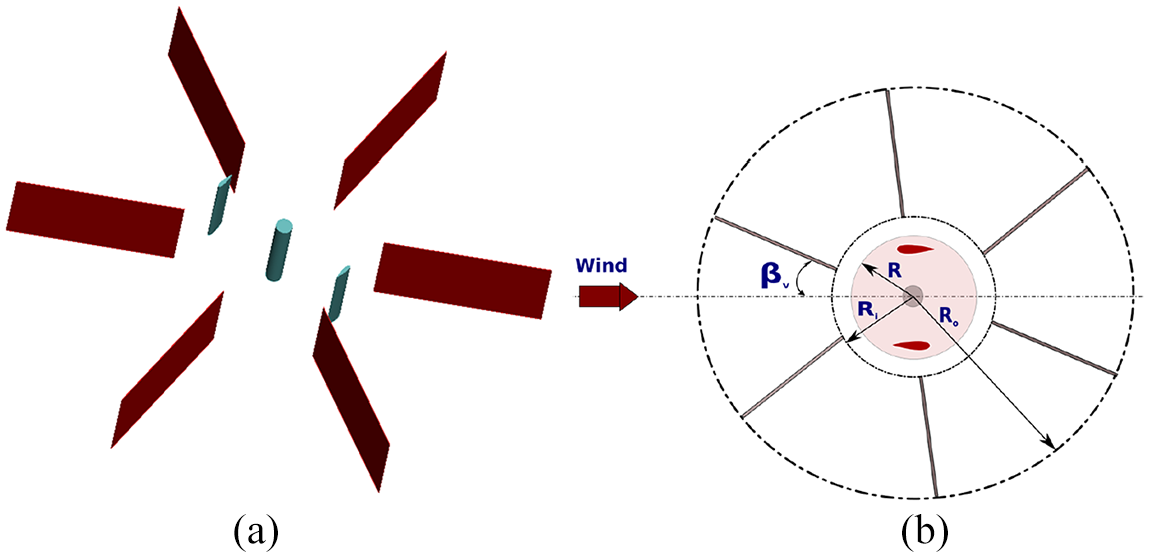
Schematic of: (a) VAWT installed inside the guide-vanes and (b) design parameters within the guide-vanes.
Blade cap
The aerodynamic characteristics of the finite span blade (3D model) are quite different from the airfoil section (2D model), as the finite span blade is a three-dimensional body. Therefore, there is a flow component in the spanwise direction. Basically, the flow over the airfoil creates sides of high pressure (pressure side) and low pressure (suction side), where the lift is generated as a result of the unbalance created by the two sides. However, as shown in Figure 3(a) the flow near the tip tends to curl around the tip from the pressure side toward the suction side, the generated circular motion near the tip is called the tip vortex, and it moves in the blade downstream. These tip vortices create a small downward flow component that is called downwash. The downwash over the finite blade tends to decrease the angle of attack and creates an excessive drag that is called induced drag, which leads to a lower lift to drag ratio compared to the infinite blade that is more obvious at high flow velocity (Anderson, 2010). Consequently, by installing a cap near the blade tip as in Figure 3(b), it avoids the flow circulation near the tip, and the finite span blade behaves as the infinite one. As a result, higher power at the high-speed ratios is produced.
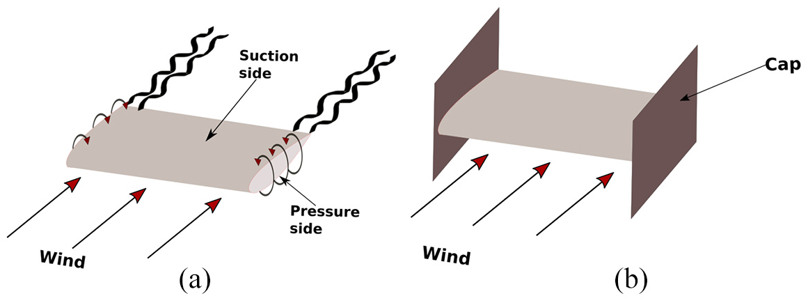
Schematic of finite span blade: (a) without cap and (b) with cap.
Numerical setup
The assessments are based on the CFD simulations that were carried out using a block-structured solver FLOWer from the German Aerospace Center (DLR) (Kroll et al., 2000). Institute of Aerodynamics and Gas Dynamics at the University of Stuttgart extended the code over the years for wind turbine applications. The time integration was carried out by an explicit hybrid 5-Stage Runge-Kutta scheme. The higher-order WENO (Weighted Essentially Non-Oscillatory) scheme for the reconstruction of the convective flux at cell boundaries together with an HLLC Riemann solver on block-structured grids of the background was applied to improve conservation of vortical structures (Kowarsch et al., 2013, 2015; Liu et al., 1994). The multigrid level 3 and implicit residual smoothing with variable coefficients were applied to accelerate the convergence. The time discretization is achieved by applying dual time-stepping according to Jameson (1991). Delayed Detached-Eddy Simulation (DDES) (Shur et al., 2008; Weihing et al., 2016) was applied among unsteady Reynolds-averaged Navier-Stokes (URANS) approach employing the Shear-Stress-Transport (SST)
The turbine model is based on the published experimental data by Li et al. (2016). The turbine model is a two-bladed rotor with a NACA0021 airfoil section. It has a radius of 1
The present study employed the fully structured mesh method. The turbine mesh initially consists of three grid components, namely, background, rotor blades, and the central shaft ( see Figure 4(a) and (b)). For evaluating the impact of the guide vanes, another component was added, as shown in Figure 4(c). The grid overlapping (Chimera) method was employed, allowing high quality mesh components to be created independently. The total number of cells in all zones based on the published procedure and mesh independence study is about 35 million, with the background dimensions shown in Figure 5 (Dessoky et al., 2019).

Computational mesh used in the simulations: Background (a), rotor with the shaft (b), and fixed guide-vanes (c).

Sectional 3D computational mesh used in the simulations (Dessoky et al., 2019).
Fixed guide-vanes 2D parametric study
The guide-vanes are surrounding the rotor; therefore, the flow velocity could be increased by the contraction through the nozzle shape. Furthermore, the guide-vanes could act as a wind direction modulator, for better flow blade incidence angle. The generated power strongly depends on the location of guide-vanes with respect to the flow. As a result, this section investigates the impact of the guide-vanes design parameter through 2D modeling to achieve the best configuration.
Guide-vanes angle (
)
In this section, a general consideration of the diffuser main design parameters, inner radius ratio (
Investigated guide-vanes angle values.

Figure 6(a) shows that at

Velocity contours at

Comparison of power coefficient
Guide-vanes outer radius design parameter
The guide-vanes design parameters, inner radius ratio (
Investigated guide-vanes outer raduis values.

Velocity contours at
Comparison of power coefficient
Guide-vanes inner radius design parameter
The inner radius of the guide-vanes can affect the wind direction and velocity. Therefore, the performance of the VAWT was computed with various inner radius ratios as shown in Table 3, with fixed outer radius ratio and guide-vanes angle of
Investigated guide-vanes inner-raduis ratio values.

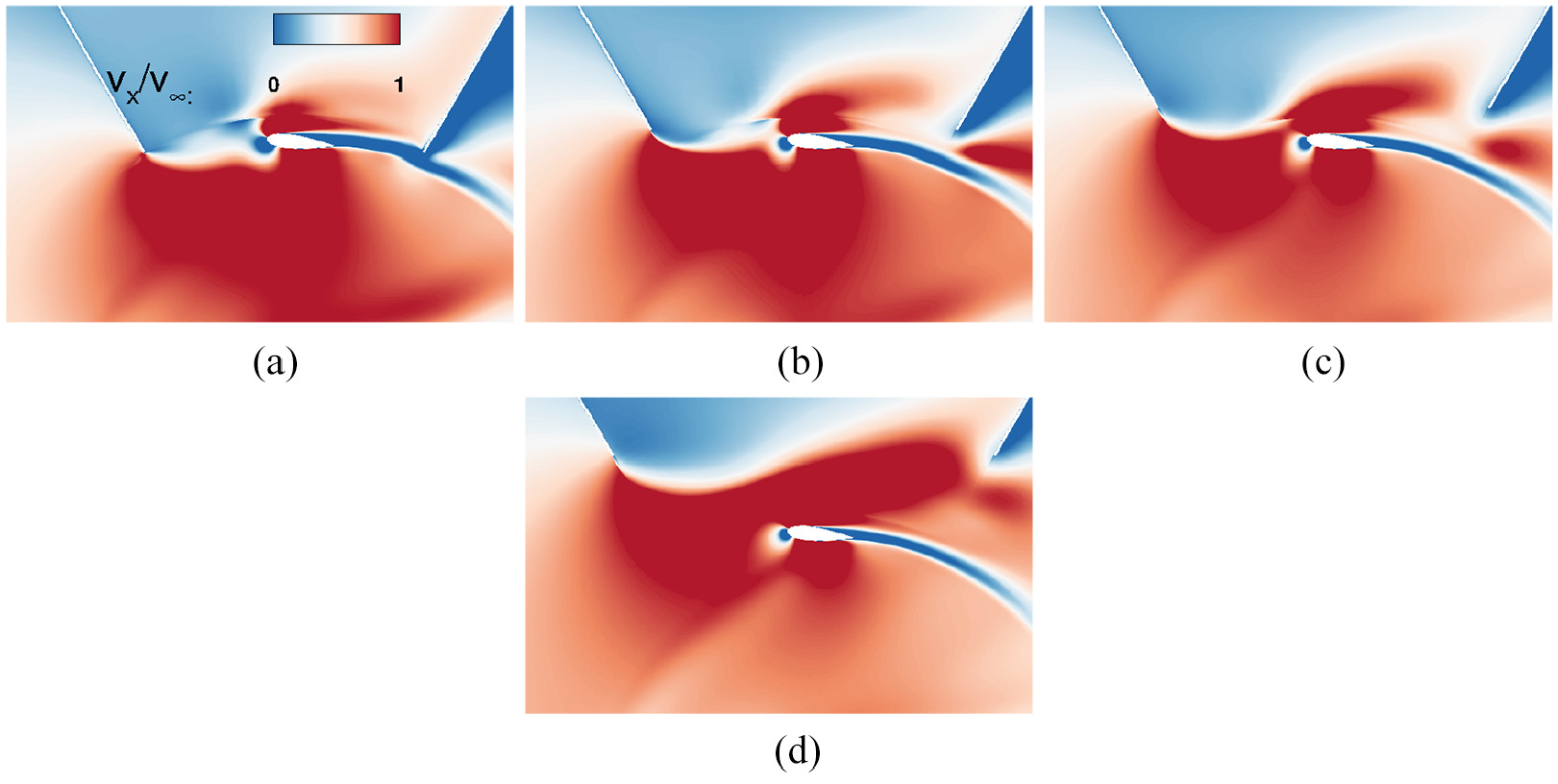
Velocity contours at
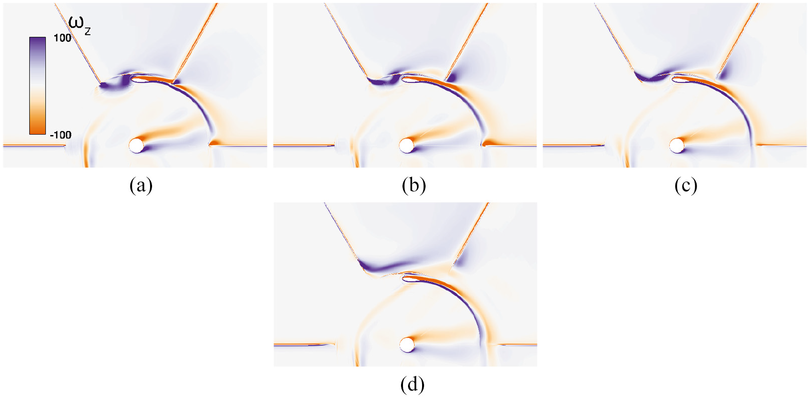
Vorticity contours at
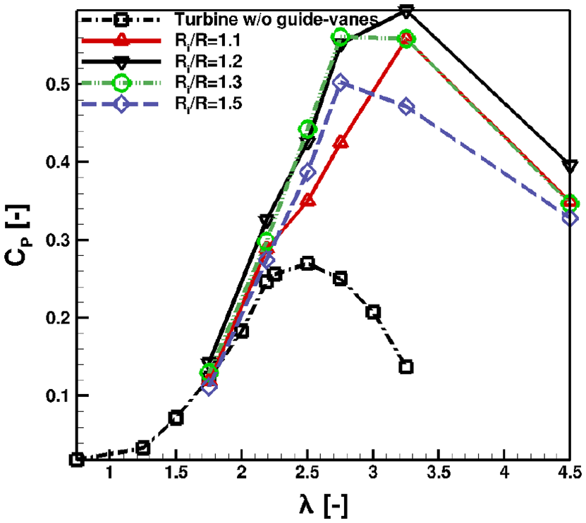
Comparison of power coefficient
3D modeling investigations
Darrieus VAWT with fixed guide-vanes
Aerodynamic assessment
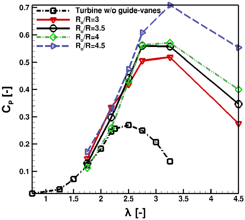
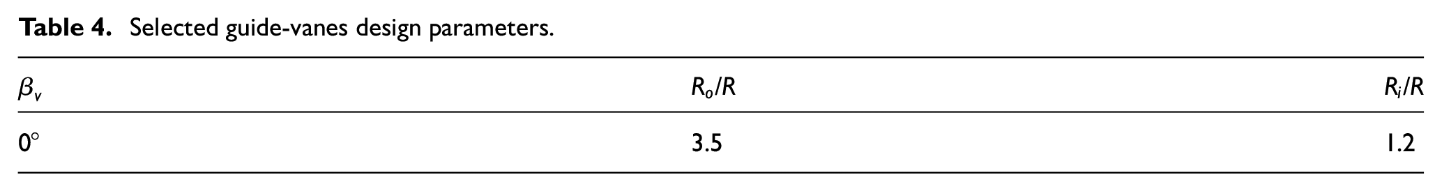
The previous section illustrated that the Darrieus turbine with a certain configuration of the fixed guide-vanes demonstrates better performance compared to the conventional turbine, as the results of accelerating and guiding the flow toward the rotor blades. For better describing how the power augmentation takes place by using the guide-vanes, a full model simulation is carried out with the design parameter that achieves the best performance during the 2D parametric study (see Table 4), the deviation of the 2D from the full model is discussed in details by Dessoky et al. (2019). Figure 13 shows that, by using the guide-vanes, the power coefficient increases by approximately 42% at
Selected guide-vanes design parameters.
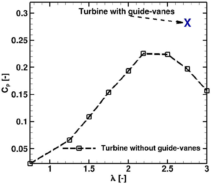
Comparison of power coefficient
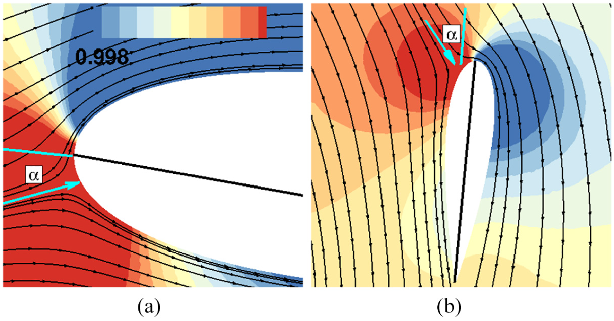
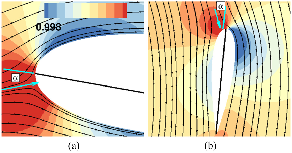
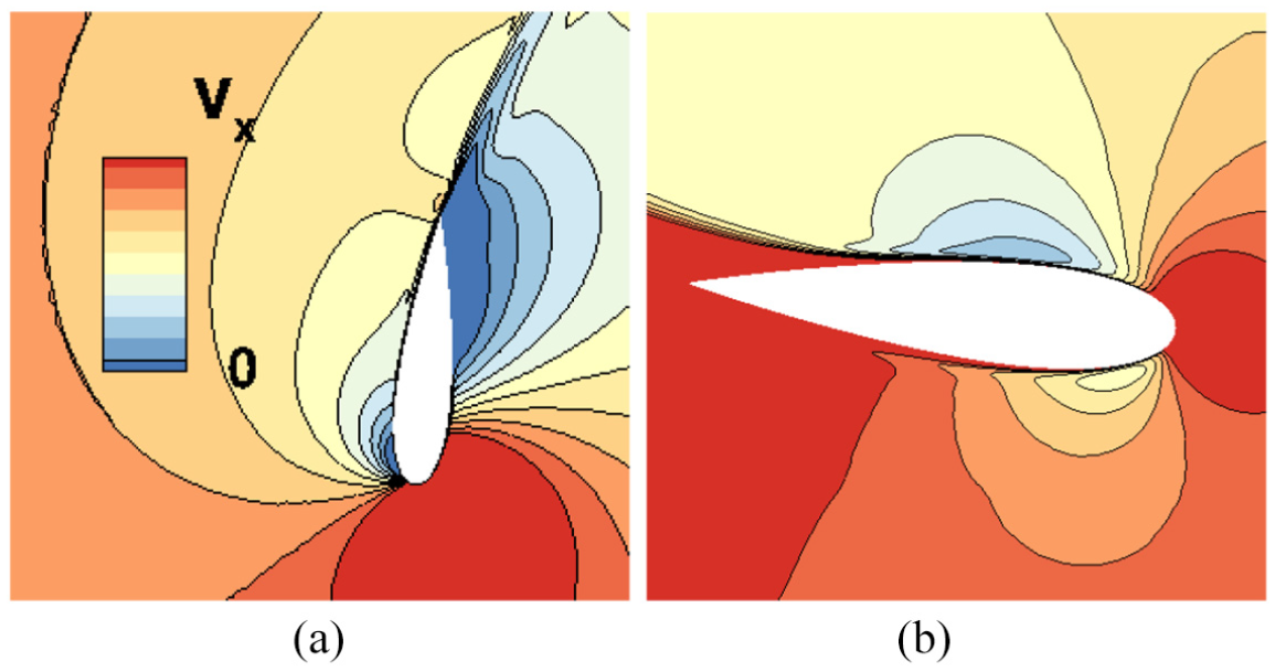
Figures 14 and 15 show that at
Pressure ratio (
Pressure ratio (
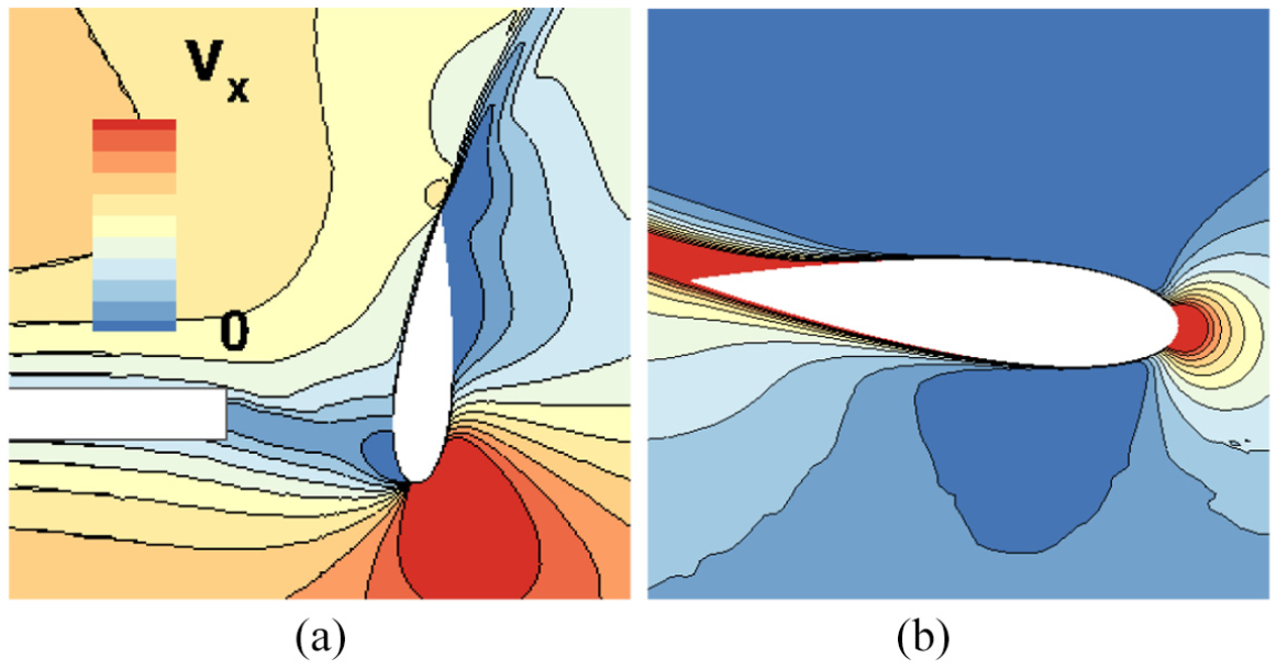
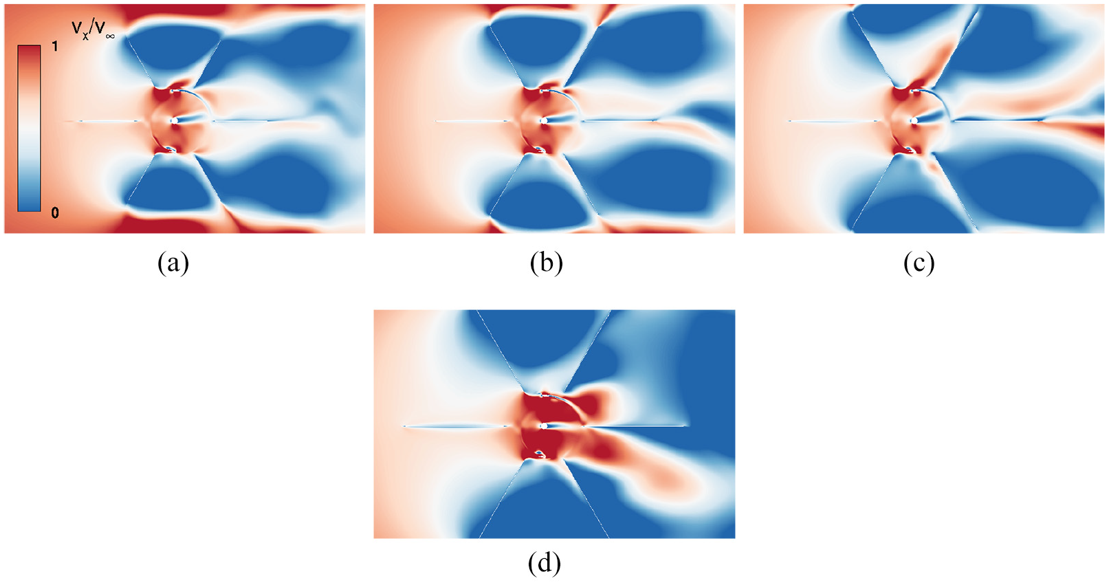
Velocity contours in m/sec of the turbine with guide-vanes at: (a)
Velocity contours in
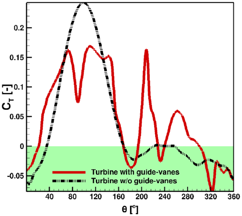
Comparison of torque coefficient
Aeroacoustic assessment
The noise transmitted from the rotor is depending on the flow displaced by the blades during the rotation (thickness noise or monopole noise), and the blades load variation (loading noise or dipole noise). The monopole noise is eternally associated with the dipole noise but not vice versa (Dessoky et al., 2019).
According to He (2013), the rotor is split into four distinct regimes, namely, upwind, leeward, downwind, and windward, as shown in Figure 19, with distinguished physical characteristics of each of them (Dessoky et al., 2019). Therefore, the observer locations are spread at the beginning and end of each region. Figure 20(a) describes the sound pressure level spectra at
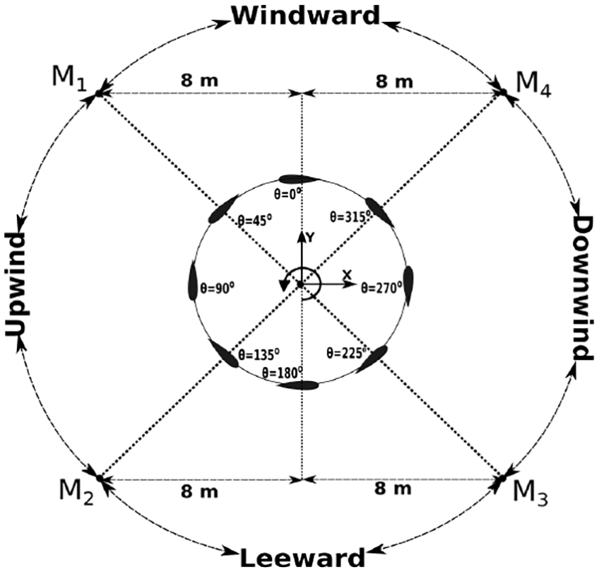
Schematic of VAWT rotor division and observer positions
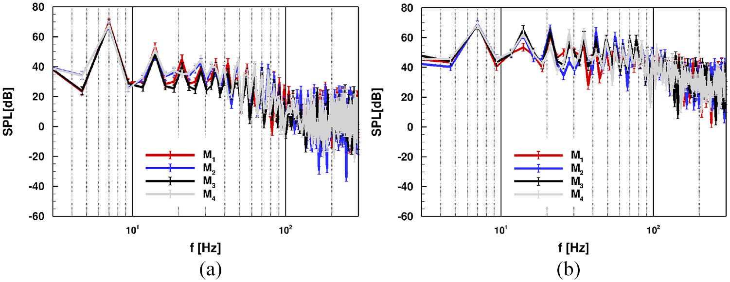
Sound pressure level spectra at the prescribed observer positions for : (a) open turbine and (b) turbine with fixed guide-vanes.
Aeroacoustic noise footprint on a carpet 50 rotor radius at the BPF for: (a) open turbine and (b) turbine with fixed guide-vanes.
Capped Darrieus VAWT
Aerodynamic assessment
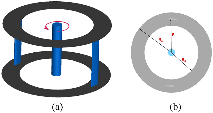
The induced three-dimensional flow by the blade tip vortices alters the pressure distributions on the blade that produce an imbalance in the wind direction, causing excessive induced drag from a pressure drag type and reduce the angle of attack as well (Anderson, 2010). The induced drag has an impact on the Darrieus turbine global power; such an impact could differ according to the speed ratio range. A cap is fixed at the tip of the Darrieus turbine blades, as shown in Figure 22. Therefore, it could avoid or partially avoid the three-dimensional flow. Two capes with different
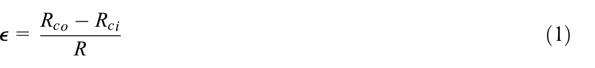
Where
Schematic of Darriues turbine with cap (a) 3D view and (b) design parameters.
The two caps configurations are examined at
Comparison of power coefficient
According to Simpson (2001) as in Figure 24 an induced unsteadiness near the junction occurs. A large horseshoe vortex exists in front of the blade, produced by the wind flow in the junction, and impinging on the blade creating a primary vortex near the blade. A secondary vortex and tertiary vortices are formed by wall shear. These vortices merge, creating a stronger large horseshoe vortex. After a while, the flow becomes completely unstable, and the developed strong vortex moves to the blade downstream. Therefore, the horseshoe vortices are observed upstream, and downstream of the blade and the incoming velocity is decelerating toward the leading edge (Bangga et al., 2017). Figure 25 shows that the vortex strength accompanied with
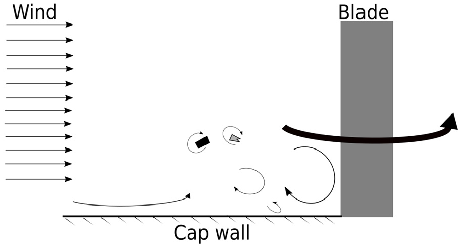
Schematic of vortex evolution near cap junction.

Wake of the Darruies VAWT with cap at
Figure 26 shows that the pressure coefficient difference is higher with
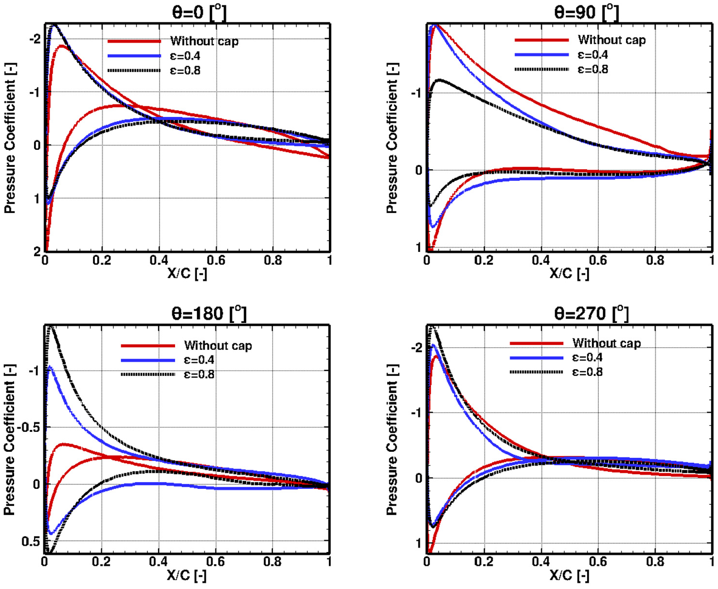
Temporal variation of the pressure distribution at different azimuth angles near to the blade tip.
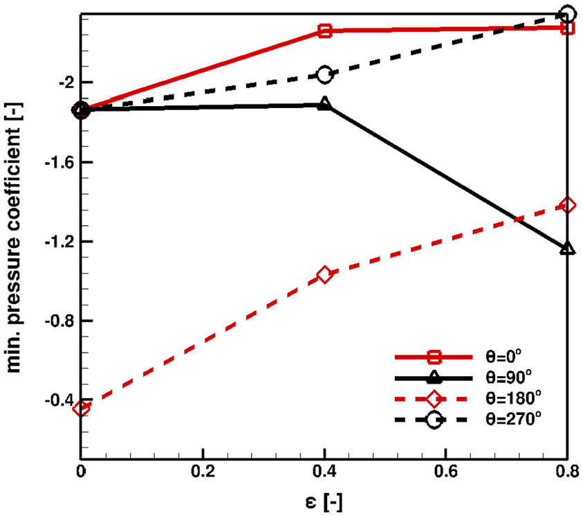
Minimum pressure coefficient for different values of
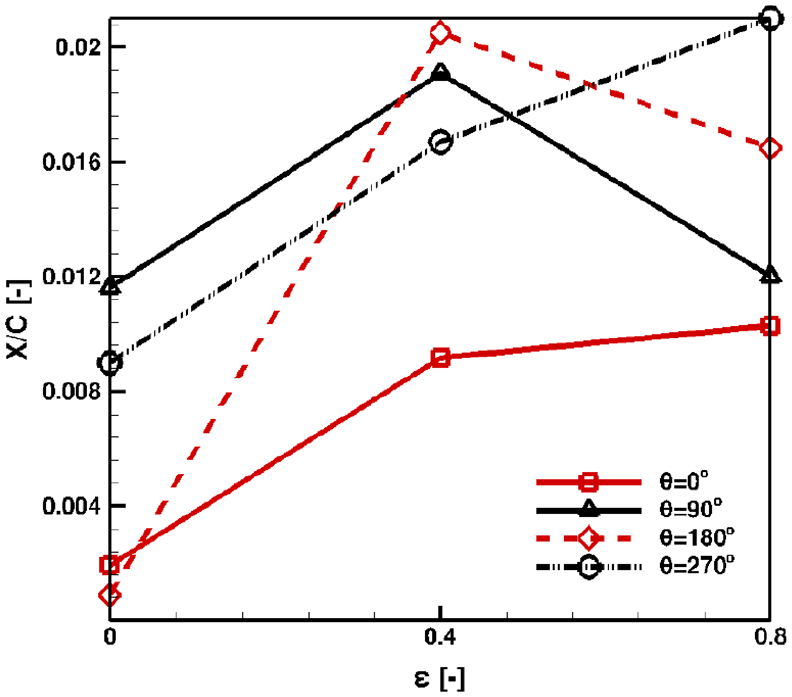
Staganation point location with respect to chord lengh for diffrent values of
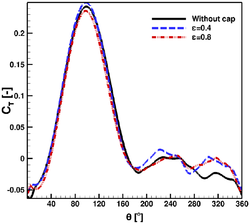
Turbine generated torque for Darrieus turbine with different configurations.
Aeroacoustic assessment
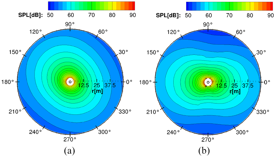
Figure 30 shows the sound pressure level footprints surrounding the turbine, based on the BPF for different turbine configurations. Cap results in a horseshoe from junction effect and reducing the effective angle of attack. However, it does not approximately affect the fluid displaced by the blade. Therefore, it is quite evident that the cap does not show any change in signal directivity and produces a little increase in the sound pressure level change the noise produced by the turbine, due to the junction effect. Furthermore, it is clear that the tip vortex has no significant contributions to the noise generated by the Darrieus VAWT. By analyzing the spectra as in Figure 31, it could be concluded that that the capped turbine shows a higher sound pressure level at higher harmonics as a reflection of the horseshoe effect on the cap surface and the blade tip. However, at the observer positions,
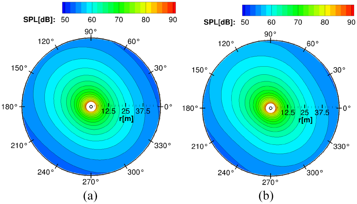
Aeroacoustic noise footprint on a carpet 50 rotor radius at the BPF for: (a) turbine without cap and (b) capped turbine (
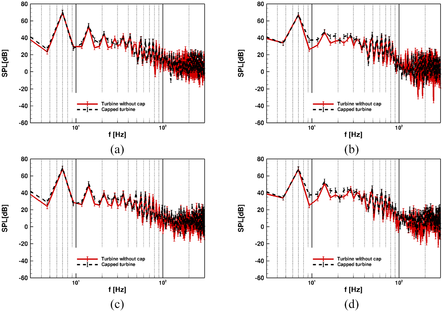
Sound pressure level spectra at observer positions: (a)
Conclusions
Darrieus VAWT has the merit to work under low wind speed and in urban area conditions, but it suffers from poor aerodynamic performance compared to horizontal axis wind turbines. The results presented in this paper show the impact of using guide-vanes incorporated in Darrieus VAWT and assess the aerodynamic and aeroacoustic performance. Therefore, 2D modeling using URANS simulation is taken on to study the effect of each design parameter of the guide-vanes to reach the best configuration. Then the full 3D model of the best configuration using high order numerical scheme with
The optimal design parameters of the guide-vanes and the impact of every single parameter on the global aerodynamic performance are introduced through 2D modeling.
The 3D modeling shows that the guide-vanes increase the generated torque around the central shaft at some azimuthal position and reduce it at some other positions. However, the average torque over a complete revolution is increased, achieving an approximately 45% increase in power coefficient at
By using the guide-vanes, the directivity of the noise signal is changed, and the total noise value increases when it is predicted at prescribed observer positions.
The capped Darrieus turbine shows about a 20% increase in power coefficient by using the cap with 0.4 thickness to radius ratio while using 0.8 thickness to radius ratio causes a 2% reduction in the power coefficient at
Footnotes
Appendix
Acknowledgements
The authors gratefully acknowledge the German Academic Exchange Service (DAAD), the Ministry of Higher Education and Scientific Research of the Arab Republic of Egypt (MoHE) for the funding through the GERLS scholarship program, the High-Performance Computing Center Stuttgart (HLRS), and Leibniz supercomputing center (SuperMUC) for the computational resources.
Declaration of conflicting interests
The author(s) declared no potential conflicts of interest with respect to the research, authorship, and/or publication of this article.
Funding
The author(s) received no financial support for the research, authorship, and/or publication of this article.