



Abstract
The use of a single optimized bump placed on the leading edge of the front blade of a counter rotating open rotor is envisaged as passive device to reduce the interaction noise at low-speed and high-thrust condition, such as takeoff. This noise reduction device is to be considered as an alternative to rear blade cropping and its penalizing effect on efficiency in cruise condition. The modified front rotor blades provide an acoustic gain that has been linked to the changes on the characteristics of the front rotor wake. The front blade modification has no strong impact on the aerodynamic performance for both takeoff and cruise operating points.
Introduction
Interaction noise contributes significantly to the noise radiated by Counter Rotating Open Rotors (CROR), especially at low-speed conditions. 1 A common solution proposed to decrease this interaction noise is to reduce the rear blade external radius to avoid, at least partially, the interaction of the rear rotor blades with the tip vortices of the front rotor. 2 The cropping, or clipping, of the rear rotor has proven to reduce effectively interaction noise at design points but leads to severe optimization constraints on shape geometry at other operating points. 3 As this interaction cannot be completely avoided, Onera and Snecma have initiated alternative researches aiming at reducing interaction noise through modifications of the wake of the front rotor while preserving the aerodynamic performance of the open rotor.
The alteration of the front rotor wake can be obtained by modifying the front rotor blade design. Actually, it is well known that placing protuberances, or serrations, on the leading edge of a wing or blade can trigger the formation of vortices. Such leading edge modifications have been recently tested, experimentally and by means of numerical simulation, on a fixed wing reproducing the spanwise circulation of an open rotor blade at takeoff operating point.4–6 The first conclusion of this study was that placing serrations along the blade span allows to generate multiple vortices, close to each other, at the trailing edge. But these multiple vortices merge together with the tip vortex before interacting with the rear rotor blades. The second conclusion is that the use of a single bump, with an optimized shape and position, allows to split the spanwise distribution of the blade circulation to obtain a wake with two co-rotating vortices that do not merge.
The present paper presents the results of the transposition of this optimized bump to the leading edge of the front blades of Onera’s HTC5 generic open rotor. 7 It is organized as follows: the baseline and modified open rotor geometries are presented in the first section; then the methods and tools used to compute the aerodynamics and acoustics are detailed; the aerodynamics and acoustics of the baseline and modified HTC5 open rotor are then analyzed and a detailed description of the flowfield around the blades and links the characteristics of the front rotor wake with the radiated noise are given; finally, it is verified that the modified front rotor blade does not result in a loss of aerodynamic performance in cruise condition.
HTC5 open rotor
Baseline geometry
The open rotor geometry used to assess the efficiency of the front rotor wake modification4–6,8 on interaction noise is Onera’s HTC5 open rotor.
7
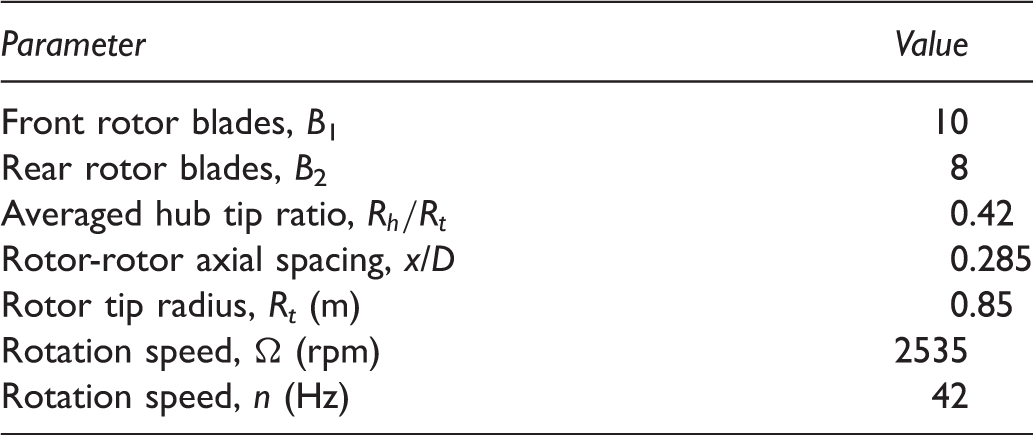
HTC5 is a generic 10 × 8-bladed open rotor in pusher configuration. The front and rear rotors exhibit same outer radii and have same rotational speed. The aeroacoustic characteristics of this open rotor has been thoroughly analyzed,
9
and the impingement of the front rotor tip vortices on the rear rotor blades has been clearly identified as the major source of the interaction noise radiated in low-speed and high-thrust flight condition (takeoff). HTC5 is considered here at 2/5 scale with simplified hub design upstream and downstream of the rotors. An overview of the open rotor is shown in Figure 1, and the main parameters are resumed in Table 1.
HTC5 open rotor. HTC5 open rotor characteristics.
Modified front rotor blade
The reduction of open rotor interaction noise by means of front rotor wake control is an active research field addressing various technological solutions such as front rotor trailing edge serrations,
10
blowing,
11
or front rotor operating point.
12
The approach followed in the present study finds its roots in the experiments of Vion et al.4–6 based on a fixed blade reproducing the spanwise circulation of HTC5 front rotor blade in takeoff condition. For this blade design, high thrust and low speed results in a leading edge separation in which a leading edge vortex develops and merges with the vortex emitted at the blade tip. In their experiments, Vion et al. have tested different shapes and positions of leading edge bumps to trigger the formation of this leading edge vortex and prevent its merging with the tip vortex. The most effective combination of shape and position has been adapted to HTC5 front rotor blades to assess its benefit from an acoustic point of view. It is presented in Figure 2. The bump is located at 80% of the blade height H, the amplitude of the deformation is set to 5% of the blade height in the spanwise direction, and 1/16th of the chord C in the chordwise direction. Only the first quarter-chord of the profile is modified in these sections. The thickness of the profiles is kept unchanged. Continuity of the surface is ensured by tangential connection with the rest of the blade surface.
Modified front rotor blade and comparison of baseline (solid lines) and modified (dashed lines) blade sections around leading edge bump position.
Computational methodology
The computational methodology used to quantify the acoustic gain provided by the front rotor blade wake modification4–6,8 relies on the classical coupling of computational fluid dynamics (CFD) and acoustic integral methods such as the Ffowcs-Williams and Hawkings (FWH) equation. 13 Onera’s methodology relies on the elsA and KIM solvers which are intensively used for open rotor aerodynamic and aeroacoustic characterization.3,14–20 The numerical setup, resumed hereafter, is similar to the one used in Delattre and Falissard 9 to analyze the influence of torque split ratio on the noise radiated by HTC5 open rotor.
CFD simulation setup
The CFD computations are carried out with Onera’s 3D aerodynamic solver elsA that is intensively used for open rotor simulations.3,19,18 The unsteady flow over the isolated open rotor at zero incidence is computed using a phase lag assumption21,22 that allows discretizing a single channel of the front and rear rotors. The physical model is based on the unsteady Reynolds averaged Navier–Stokes equations solved in the compressible regime for an ideal gas. The turbulence is modeled using a Front and rear rotor blade near-body grids.
FWH noise radiation
The noise radiated by the open rotor is computed with Onera’s KIM code
33
solving the FWH equation
13
in the temporal domain. Both solid and porous surface formulations of the FWH equation are implemented in KIM. If the porous formulation is best suited to quantify the noise directivities because it accounts for all sources as well as non-uniform propagation and flow gradients, the solid surface formulation allows analyzing the noise source mechanisms and their locations on the blades. It has been shown in Delattre and Falissard
9
that both formulations lead to the same conclusions when used to perform a comparative analysis of the noise radiated by open rotors at takeoff condition. The present study, focusing on the acoustic gain resulting from the modification of the front rotor wake, is thus performed using the solid surface formulation of the FWH equation. The data used for the acoustic computations consist in the unsteady wall pressure on the front and rear rotor blades as well as on the front and rear sections of the rotating hub displayed in Figure 4. The noise radiated by each rotor is computed separately over a phase-lag period and the total noise is obtained by summing the temporal acoustic signatures of each rotor. Farfield noise directivities are computed for observers located on a circle arc of radius equal to 10 rotor diameters.
Solid surfaces for FWH noise radiation computations.
Effect of front rotor wake modification on aerodynamics and acoustics at takeoff
Flight condition and operating point
Takeoff flight condition.

Takeoff operating point.
Aerodynamics of baseline and modified open rotors
The interaction noise emitted by an open rotor at takeoff depends highly on the intensity and phasing of the interaction of the front rotor wake with the rear rotor. Since both baseline and modified HTC5 open rotor exhibit same rear rotor geometry, the focus is put on the analysis of the front rotor aerodynamics.
The pressure distribution and friction lines on the suction side of the baseline and modified front blades are illustrated in Figure 5. The baseline blade operating point is characterized by a spanwise pressure drop along the leading edge resulting from a flow separation: The boundary layer separates and rolls up in a spiral fashion as for the delta wings35–37 to generate a leading edge vortex. The presence of this vortex, confirmed by the friction lines, is typical of the behavior of open rotors at low-speed and high-thrust condition.3,12,38 This is particularly true for designs, even modern, optimized using an aero-only criterion at high-speed flight condition.
39
For the baseline front rotor blade, the leading edge vortex merges with another vortex emitted near the blade tip9 to form what will be referred to hereafter as the front rotor tip vortex. For the modified blade, the bump perturbs the leading edge vortex roll-up and the pressure drop vanishes in its vicinity. A new vortex roll-up starts above the bump, generating a new low-pressure area. This splitting of the vortex roll-up is also visible through the friction lines orientation.
Time-average wall pressure distribution and friction lines of baseline (left) and modified (right) front blade suction side for takeoff condition.
The modification of the vortex roll-up along the leading edge results in a loss of thrust at the corresponding spanwise location, around Blade section thrust coefficient of baseline (- - -) and modified (–) HTC5 front rotor.
Similarly to the experiments of Vion et al.4–6 on the fixed blade, the two thrust spanwise distributions of the baseline and modified front blades lead to different developments of the vortical wake downstream the front rotor. The relative Mach number distribution downstream the front blade is plotted in Figure 7. The local extrema of the Mach number (red/blue dipole pattern at tip radius) in the wake indicate the location of the tip vortex. In case of the modified front blade, another dipole pattern of Mach number variation (green/red spots) appears at a lower radial position and on the side of the wedge.
Mach number distribution behind the baseline (left) and modified (right) front rotor blades.
A better characterization of the baseline and modified blade tip vortices is obtained by tracking the vortex and interpolating the flow variables on a patch normal to the vortex emission line (see Figure 8). The flow conservative variables are then used to determine the local wake and vortex characteristics such as entropy deviation, displayed in Figure 8, or tangential and out of plane velocity components displayed in Figures 9 and 10. The vortices are not circular, due to the influence of the adjacent tip vortices,
9
but exhibit similar values of core radii and maximal tangential velocities. The tip vortex of the modified blade is more circular which suggests a lesser influence of the adjacent tip vortices and thus a lower intensity, in terms of circulation, of the tip vortex.
9
The tangential velocity decay far from the tip vortex center is much less coherent for the modified blade wake due to the presence of the secondary co-rotating vortex. Another major difference is observed on the axial velocity deficit in the vortex core. For the baseline front rotor blade, a significant axial velocity deficit characterizes the tip vortex while for the modified blade, the two co-rotating vortices exhibit a weaker velocity deficit in their core. To compare more precisely the tip vortices, the velocity and pressure fields computed on the patches have been extracted on lines, displayed in Figure 11(a), passing through the tip vortex cores for the baseline and modified blades and through the secondary vortex for the modified blade. The in-plane velocity curves, displayed in Figure 11(b), show that the tip vortex of the baseline and modified front blades have same core radii and similar values of maximal tangential velocities. The slope of the tangential velocity in the vortex core is slightly steeper for the modified blade, which is in agreement with the deeper pressure drop in the vortex core displayed in Figure 11(c). The amplitudes of the out-of-plane velocity deficit in the core of tip vortex and secondary vortex emitted by the modified blade, displayed in Figure 11(d), correspond respectively to 85% and 60% of the amplitude of the out-of-plane velocity deficit in the core of the baseline tip vortex. Following the trends observed in Delattre and Falissard,
9
the interaction of the vortical wake of the modified front blade with the rear rotor blade should result in lower levels of interaction noise.
Tip-vortex tracking patch positions, emission lines, and entropy deviation on patches, Front rotor tip-vortex in-plane velocity component computed on tracking patch (a) Baseline front blades and (b) Modified front blades. Front rotor tip-vortex out-of-plane velocity component computed on tracking patch (a) Baseline front blades and (b) Modified front blades. Tip-vortex fields extracted on lines passing through primary vortex cores for baseline front blades (–) and modified front blades (-.-) and through secondary vortex core for modified front blades (- - - -) (a) extraction lines; (b) in-plane velocity; (c) pressure and (d) out-of-plane velocity.


With such differences in the wake of the front blade, the interactions with the rear blade should be significantly different. The time evolution over a chorochronic period and mode amplitude of the spectral decomposition of HTC5 front and rear blade thrust coefficients are plotted in Figure 12. The mean values of the front and rear rotor thrust are the same for both configurations. This confirms that the front rotor wake modification has no impact on the average performance of the front and rear blades. The fluctuations of the thrust integrated over the whole blade have smaller amplitude for the modified blade with respect to the baseline geometry. This is true for both front and rear rotors. The spectral decomposition of the thrust shows that this is due to a significant reduction of the amplitude of the first mode. The main reduction is observed for the rear blade. Yet, this does not necessarily mean that the pressure fluctuations on the rear blade are smaller in every section since their contributions to the integrated thrust depend on the blade shape, mainly its sweep distribution, and on the flow distortion: swirl, contraction, and acceleration. The evolution over a chorochronic period of the rear blade spanwise distribution of the thrust coefficient (integrated along the blade chord), presented in Figure 13, indicates clearly that the maximal amplitude of the thrust coefficient is much lower for the open rotor with modified front rotor blade.
Time-evolution over a chorochronic period and mode amplitude of the spectral decomposition of HTC5 front and rear blade thrust with baseline (- - - -) and modified (–) front rotor. Front and rear blades azimuthal fluctuations of sectional thrust coefficient over a chrorochronic period for baseline (left) and modified (right) front blade.

Aeroacoustics of baseline and modified open rotors
The directivity of the front and rear rotor fundamentals of the interaction tones most contributing to the radiated noise and of the overall sound pressure level (OASPL) radiated by HTC5 with baseline and modified front rotor blades are plotted in Figure 14. Denoting by BPF1 and BPF2, the blade passing frequencies of the front and rear rotors, respectively, the interaction tones most contributing to the global noise are the first interaction tone at frequency Sound pressure level directivities of the fundamentals, dominant interaction tones, and over all sound radiated by HTC5 open rotor at takeoff with baseline (dashed lines) and modified (solid lines) front rotor blades.
The sound pressure level directivities radiated separately by the front and rear rotors are compared for the two blade designs in Figures 15 and 16. It is interesting to note that the modified front rotor blade reduces the interaction noise radiated separately by each rotor. This behavior, similar to the one observed in Delattre and Falissard,
9
indicates that the front rotor contribution to the interaction noise associated to the mutual effect of the front and rear rotor potential flows depends on the potential field of the front rotor itself and not only on the potential field of the rear rotor.
Sound pressure level directivities of the fundamentals, dominant interaction tones, and over all sound radiated by the front rotor of HTC5 at takeoff with baseline (dashed lines) and modified (solid lines) front rotor blades. Sound pressure level directivities of the fundamentals, dominant interaction tones, and over all sound radiated by the rear rotor of HTC5 at takeoff with baseline (dashed lines) and modified (solid lines) front rotor blades.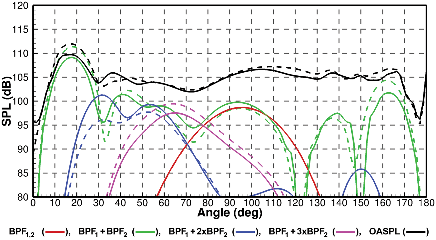

Correlating the wake modification and the acoustic gain
To better understand the origin of the acoustic gains, an acoustic source analysis has been performed on the rear rotor blades. The method used for this analysis is based on a functionality of the KIM solver, which allows recording for an observation point the contribution in terms of amplitude and phase of the elements discretizing the surface used as input data for the acoustic computation, i.e., in our case the blade and hub surfaces. The results of this analysis, at 25° directivity angle and for the first interaction tone are plotted in Figure 17. For both cases, high amplitude contributions (in red color) are located at the blade leading edge especially around the radius Area of high contribution in amplitude (left) and corresponding phase (right) of the rear blade unsteady wall pressure to the first interaction tone for 25° directivity angle (a) HTC5 with baseline front blades and (b) HTC5 with modified front blades.
The differences in amplitude and phase between the two cases are plotted in Figure 18. The only area on the rear blade where differences are significant both in terms of amplitude and phase is located at the blade leading edge between Differences of the contributions in amplitude (left) and phase (right). Paths of the tip vortices emitted by front rotors with baseline (▴) and modified (▾) geometries.

The secondary vortex is visible in the vicinity of the rear blade in Figure 20. In this figure, the front blade tip vortex is materialized by the vorticity iso-value surfaces in gray. Vorticity contours are also shown in two parallel planes flanking the rear blade. These contours are colored by the vorticity normal to the planes. The iso-value surfaces link the circular blue contour lines corresponding to the footprint of the tip vortex on the slicing planes. In the blade root region, the red contour lines correspond to the footprint of the front blade wake. These footprints are linked two by two showing the full intersection of one front blade vortex sheet with each slicing plane. For the baseline geometry, the tip vortex and the root wake are linked by a weak vorticity sheet. For the modified blade, they are separated by the secondary vortex characterized by the blue contours. The blue color indicates that it is co-rotating with the tip vortex. Between these two co-rotating vortices there is yet another sheet with red contours. This spot corresponds to a vorticity area that was ripped off from the counter rotating vortex sheet. These intermediate vorticity regions which are only present for the modified blade are cut by the rear blade between Instantaneous vorticity contours and vorticity iso-surface of the baseline and modified front blade wakes interacting with the rear blade (a) Baseline front blade wake impact on rear blade and (b) Modified front blade wake impact on rear blade. Rear blade thrust fluctuation in two sections for the open rotors with baseline (- -) and modified (—) front rotor blade.

Effect on aerodynamic performance at cruise
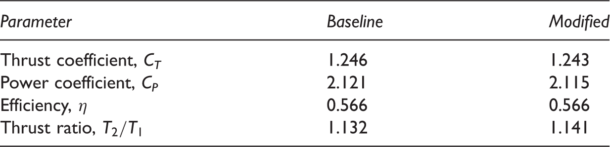
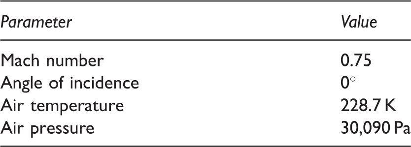
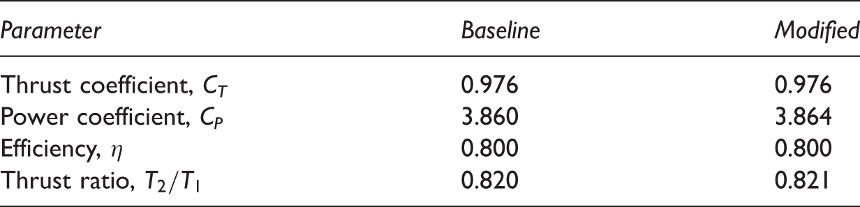
High-speed computations have been carried out to evaluate the impact of the modified front rotor blade on aerodynamic performance. At high speed, the aerodynamic behavior of the blades changes. The leading edge vortex which was contributing to thrust via vortex lift at takeoff is strongly reduced. A steady CFD computation has been carried out for a cruise flight condition at Mach number Time-average wall pressure distribution and friction lines of baseline (left) and modified (right) front blade suction side for cruise condition. Cruise flight condition. Cruise operating point.
Conclusion
A noise reduction concept has been evaluated on Onera’s HTC5 generic open rotor design for takeoff conditions at which interaction noise is of main importance. This concept was initially developed by Vion et al.4–6 on a fixed blade reproducing the spanwise circulation of a rotating blade. It consists in a single bump placed on the leading edge of the front rotor blades and allows controlling the roll up of the vortex generated at the blade leading edge at low-speed and high-thrust flight condition. The bump optimized experimentally, in terms of location, shape, and dimensions, to split the tip vortex into two co-rotating vortices and a counter rotating wake has been transposed in the present study to the front rotor blades of HTC5 open rotor and evaluated numerically from aerodynamic and acoustic point of views.
The aerodynamic study has confirmed that the modified front rotor blades generate a vortical wake with two co-rotating vortices and that the aerodynamic performance of the open rotor is not altered. Acoustic computations confirmed the noise reduction on the OASPL for almost all directivity angles. This noise reduction is obtained by decreasing the maximum noise levels radiated by the first interaction tones linked to the impingement of the front rotor wake on the rear rotor blades. The two co-rotating vortices generated by the modified blades exhibit lower circulations and less intense axial velocity deficits than the initial single tip vortex emitted by the original front blade design. An analysis of the acoustic sources on the rear blades has clearly linked the noise reduction to the changes of the front rotor blade wake.
Finally, aerodynamic computations in cruise conditions have shown that the modified blade has a negligible impact on performance for high-speed operating points. The front rotor wake modification presented here could be an alternative of the clipping of the rear rotor commonly proposed to reduce interaction noise at takeoff. Moreover, the use of open rotor with unclipped rear rotor should result in better efficiency in cruise condition than open rotors with cropped rear blades that do not counter all the swirl generated by the front rotor.
Footnotes
Declaration of conflicting interests
The author(s) declared no potential conflicts of interest with respect to the research, authorship, and/or publication of this article.
Funding
The author(s) received following financial support for the research, authorship, and/or publication of this article: The authors acknowledge the support of Snecma for this study through the funding of L. Vion's PhD thesis.