
Abstract
This study investigates optimized hydraulic cylinder positioning for erecting and lowering small-scale wind towers. Static structural analysis was performed for multiple connection configurations to minimize required force while maintaining geometric feasibility. A locally available 3000-psi hydraulic cylinder was evaluated, and a prototype was constructed to compare theoretical energy consumption with measured electrical energy trends. Results indicate that the optimal connection point occurs at the horizontal distance of 7.5 ft from the tower and the vertical distance of 5 ft from the base; however, locally available cylinders lack sufficient capacity for controlled lowering, requiring custom designs for safe retraction. The findings highlight placement constraints, cylinder capacity limits, and energy consumption characteristics, demonstrating the potential for improved hydraulic solutions in residential wind tower systems.
Keywords
Highlights
• Optimized hydraulic cylinder placement reduces force demand in small-scale wind tower erection • Geometric feasibility limits for hydraulic cylinder positioning are quantified • Prototype testing validates energy consumption trends and capacity constraints • Force and capacity constraints governing hydraulic tower retraction are identified
Introduction
Wind energy has emerged as a prominent renewable energy source, and its development has gained significant momentum in the United States. The global wind energy statistics compiled by the Global Wind Energy Council (GWEC) demonstrate a substantial increase in cumulative installed wind capacity. According to the Global Wind Report 2025 published by the Global Wind Energy Council (GWEC), a record 117 GW of new wind power capacity was installed globally in 2024 (GWEC, 2025). The report further indicates that wind energy deployment continues to expand into new geographic regions while strengthening its role in the global energy transition. In addition, GWEC emphasizes that annual wind power deployment may need to increase to approximately 320 GW per year by 2030 to satisfy global renewable energy transition targets and energy security demands. These trends demonstrate the rapidly growing scale and significance of wind energy infrastructure worldwide. Consequently, the development of efficient wind turbine installation and erection systems is becoming increasingly important to support future large-scale deployment.
Wind turbines towers are essential to wind energy production. Since winds generally increase with increasing altitude, larger blades and wind towers are preferred. As wind can flow more freely at higher altitude, without much friction from trees and other obstructions, wind towers are generally tall. The tower height is often related to the turbine rotor diameter; however, this relationship varies depending on turbine scale and design requirements. For small-scale wind turbine systems considered in this study, the tower height is typically on the order of 1 to 1.5 times the rotor diameter (Basu, 2010). Based on the height of the tower and subsequently the rotor diameter, wind towers can be classified as Small (household), Medium and Large (Tummala et al., 2015). The present study focuses specifically on small-scale wind tower systems, where tilt-up erection methods are commonly employed.
Previous studies have investigated wind energy systems, aerodynamic behavior, and numerical simulation approaches for wind-related engineering applications. Chang and Starcher (2019) evaluated the feasibility of wind and solar energy investments, while Miller et al. (2013) reviewed computer-aided numerical simulation techniques used in wind energy analysis. Additional studies examined wind-induced behavior and aerodynamic characteristics of structural systems relevant to wind tower applications (Chang et al., 2014; Ong et al., 2020). General wind turbine engineering, operational behavior, and renewable energy deployment have also been extensively discussed in the literature (Hau, 2013; Mathew, 2006).
Existing research has further addressed construction-stage structural behavior, erection-related analysis, and numerical modeling approaches for temporary structural systems. In addition, industry standards such as IEC 61400 provide general design and operational guidance for wind turbine systems (IEC, 2019). However, publicly available structured methodologies specifically addressing hydraulic cylinder positioning, geometric feasibility, and force evaluation for small-scale tilt-up wind tower systems remain limited. Therefore, the present study focuses on developing a design-oriented engineering framework for hydraulic cylinder positioning based on static analysis and experimental validation under practical geometric and hydraulic constraints.
Several methods have been proposed for the erection of wind towers based on the type of tower. A lattice tower erection method has been proposed in which the tower is erected sectionally. A nacelle resting on a carrier is used to raise the second section with the first section already fixed to the foundation (Von Ahn, 2012). Another method describes the wind tower to be erected by sections also with each section composed of a mantle plate which are sequentially arranged at the erection site. When the mantle plates are assembled, the section is attached to the lower end of the tower and another section is arranged likewise (Trame and Müller, 2015). In contrast to sectional erection methods typically used for larger systems, tilt-up configurations using hydraulic cylinders are frequently adopted for small-scale installations due to their simplicity and reduced equipment requirements.
The primary objectives of this study are to investigate hydraulic cylinder positioning in tilt-up wind towers, particularly for small-scale applications, by defining a geometric feasibility region, identifying force and capacity limits during erection and retraction, and validating energy consumption trends through prototype testing. The study presents a design-oriented engineering framework based on static analysis and experimental validation.
Background
The use of cranes is the predominant method for wind tower erection and maintenance. However, crane mobilization, site access requirements, and operational downtime often represent a significant portion of installation costs, particularly for small-scale wind towers. While crane-free hydraulic erection methods are available in practice, their economic effectiveness depends strongly on cylinder capacity, placement geometry, and force demand throughout erection and lowering. Without optimized positioning, hydraulic systems may require oversized components or custom fabrication, which can offset potential cost advantages. As a result, the design and evaluation of hydraulic cylinder placement plays a critical role in improving both the technical feasibility and economic practicality of small-scale wind tower erection systems. In this context, the “evaluation” of hydraulic cylinder positioning is carried out through a structured assessment of feasible configurations under geometric and capacity constraints.
For small household wind turbine towers (10–98 ft) (3.04–29.87 m), the use of hydraulic cylinders eliminates the need for cranes and the associated costs, offering a promising alternative. By introducing a hinge joint slightly above the tower’s base, wind turbines can be efficiently erected and lowered. Although no standardized terminology exists, this approach is commonly used in practice and is referred to in this study as the hydraulic erection method. This methodology is particularly suitable for small-scale wind tower systems, where geometric constraints, constructability, and hydraulic erection feasibility become important design considerations.
The focus of this study is to investigate the structural behavior of a compact residential wind tower and its hydraulic cylinder, with the objective of identifying effective positioning configurations that improve safety and energy efficiency during erection and lowering. The evaluation of hydraulic cylinder positioning for wind tower erection holds significant promise for improving efficiency, cost-effectiveness, and sustainability of wind energy projects. Optimal hydraulic cylinder positioning in the system can help ensure a safe and energy efficient erection process. The analysis is limited to static conditions as an initial design-level investigation. In practical applications, hydraulic erection is typically performed under mild wind conditions and slow hydraulic movement, where static gravitational loading governs the response. Dynamic effects such as wind loading during erection and hydraulic system behavior are not considered in the present study and are identified as areas for future work during erection.
Structural analysis of hollow steel sections
Although all forms of wind towers exist, the steel tubular towers are the type most employed. Tubular towers are conical with their diameter increasing toward the base. Taller towers require larger diameters of their section to carry their weight and to avoid structural failure (Basu, 2010). Buckling is the most common failure type for all structures such as columns or towers.
Without a minor axis of bending, the members’ design and analysis become more straightforward. The structure either undergoes yielding or local buckling. The buckling of hollow circular steel sections is discussed in Chapter F: Design of Members for Flexure of the AISC Steel Manual (AISC, 2023). Based on the AISC Specification for Structural Steel Buildings, the classification and design of round hollow steel structures follow specific guidelines. To qualify as a round hollow steel structure, the ratio of the outer diameter (D) to the thickness (t) must satisfy equation (1).


For local buckling, the section must be confirmed as either compact, non-compact or slender based on Table B4.1b of the AISC Specification (AISC, 2023). Compact sections’ limit state of flange buckling is non-existent. For non-compact sections, however, equation (3) is utilized.

Similarly, equation (4) gives the nominal moment capacity for sections judged to have slender walls.


Fcr is the critical stress, and Mn is the nominal moment capacity.
Buckling and buckling behavior of hydraulic cylinders
Industries present various methods for calculating the buckling strength of a hydraulic cylinder, often supplying customers with charts or tables to help them identify the hydraulic cylinder suitable for their requirements. These calculations are based on Euler’s equation presented in equation (6).

It should be noted that the above method only considers the diameter of the piston rod, making it a simple and convenient approach for engineering applications. Models representing the hydraulic cylinder solely based on the cross-section of the piston rod are referred to as RD (rod diameter) models in this context.
Energy calculation of the hydraulic system
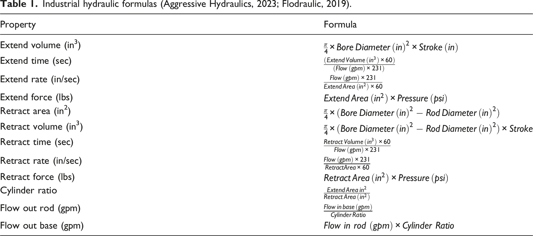
Industrial hydraulic formulas (Aggressive Hydraulics, 2023; Flodraulic, 2019).
Methodology
Structural system
Structural analysis was conducted to determine the compressive forces occurring in the piston rod of the hydraulic cylinder at various positions. These evaluations were performed across a range of feasible geometric configurations to identify effective positioning for the system under consideration.
The tower studied in this research is of small-scale household size, standing at a height of 101 ft (30.78 m). It consisted of a base section with a height of 4 ft (1.22 m), extending from the ground surface to the hinge point. The upper section of the tower measured 97 ft (29.56 m) in height. The dimensions of the tower were selected as representative of small-scale wind tower systems. The base of the tower was cylindrical with a radius of 30.6 inches (0.77 m), while the upper section had a taper ratio of 0.0384 in/in and a top radius of 8.16 in. (0.207 m). The thickness of the tower wall is determined to be 0.311 in. (0.0079 m). The wind tower is considered a long linear tapering tower and all other additions such as ladders were neglected. This simplified representation is adopted to enable a first-level structural assessment while maintaining computational tractability. Typical steel with a modulus of elasticity of 29,000 ksi (199,947.04 MPa) and yield strength 50 ksi (344.74 MPa) was considered as material for the tower build.
Due to the varying dimensions and shapes of the tower sections, as well as the presence of additional components such as internal platforms, ladders, and equipment rooms, determining the exact weight and COG of the assembled tower becomes complex. Detailed calculations and engineering analysis are typically required to accurately estimate these parameters. For the simplicity of the research in the present study, the wind tower was considered based on the provided specifications, assuming a uniform shape and known weight. This assumption is consistent with the study’s focus on static structural behavior and preliminary design evaluation. Figure 1 displays a two-dimensional representation of the wind tower, detailing all its parts and dimensions as explained earlier. Wind turbine tower components.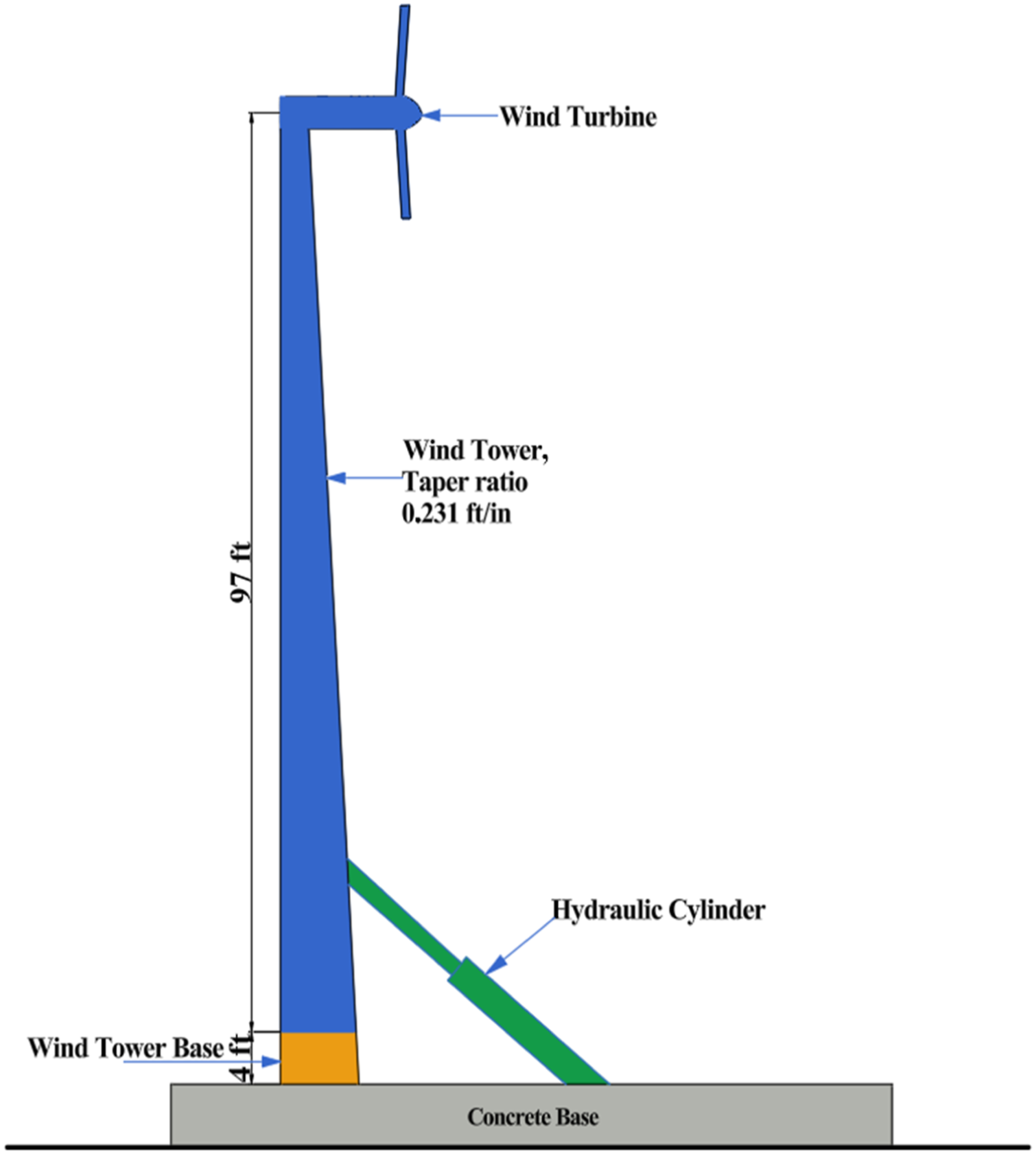
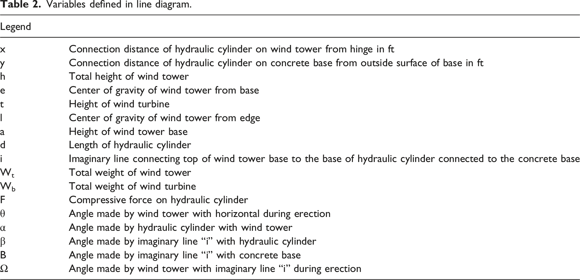
Structural analysis ascertains the load borne by the hydraulic cylinder during the process of lifting the tower from its resting position to the erect position, as well as returning it to the resting position when required. The assessment of load and stress is performed through a static analysis of the system, assuming idealized boundary conditions with zero moment at the hinge connection. Figure 2 shows the line diagram of the hydraulic erection system at an angle with the horizontal, respectively. Line diagram of hydraulic erection system at an angle with horizontal.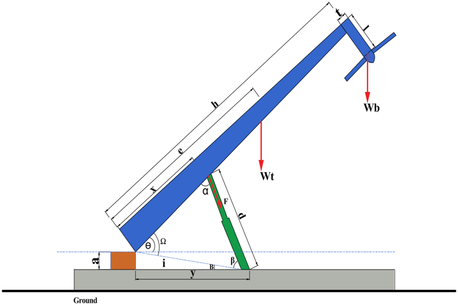
Referring to Figure 2, an angle θ was considered between the wind tower and the horizontal, where the hinge is located. This angle was used to determine the position of the tower with θ = 90° when the tower is erect while θ = 0° when the tower is in horizontal position.
The two variable x and y define the connection of the hydraulic cylinder with the wind tower and the ground, respectively, where “y” is measured from the outer edge of the base and “x” is the connection distance from the top of the base to the hydraulic cylinder connection point. “d” being the length of the hydraulic cylinder increases progressively as the tower is raised and subsequently decreases as it is lowered. An imaginary line from the hinge to the base of the hydraulic cylinder gives two more variables upon which the static analysis of the system is based. “B” is the angle of inclination depending upon the base height “a” and “y.”
The length of the imaginary line is also an important parameter. Although it remains constant throughout the erection or retraction process, it can be used to calculate the length of the hydraulic cylinder throughout the progression. The length “i” can be calculated using Pythagoras theorem considering the base is at a 90° with the ground.
Variables defined in line diagram.
Using static analysis, the moment of the hinge can be taken as zero and as such the force required by the hydraulic cylinder can be determined as.

With the force on the hydraulic cylinder calculated it becomes a simple task to calculate the reactions at hinge using the formula for equilibrium, with 

Similarly,

“⍺,” the angle between the hydraulic cylinder and the wind tower changes as the tower is erected or lowered. This angle affects the reactions and can be obtained using sine and cosine laws.
A standard two phase telescopic hydraulic cylinder was selected for carrying out analysis after determining its local availability. The dimensional constraints were considered before selecting the appropriate hydraulic cylinder. (1) The maximum total length of locally available telescopic hydraulic cylinders was found to be 11–12.55 ft (3.35–3.82 m). (2) Total available length when the tower is lowered is 5.052 ft (1.677 m). (3)
Using the above conditions, a locally available 3000-psi (20.68-MPa) standard hydraulic cylinder was selected based on dimensional constraints of the system. Manufacturer specifications indicated a closed (retracted) length of approximately 12.55 ft (3.82 m), which satisfied the minimum length required for full erection. Using these specifications, the governing geometric equations were developed to determine the feasible range of connection points on the tower and on the concrete base. Geometric feasibility constraints are defined for both fully erect and fully lowered configurations.
Considering the tower is fully erect,
Considering the tower is in a fully lowered position, the controlling equation considers the largest section of the cylinder as responsible for carrying the wind tower in its fully lowered state.
Using the Cosine law in the triangle, equation (12) can be formulated when the hydraulic cylinder is at a fully lowered condition (see Figure 3). Hydraulic erection system in fully lowered condition.
A structured parametric evaluation was performed within the defined feasible geometric region to assess the influence of cylinder connection parameters (x, y) on force demand throughout the erection process. The equations were used to plot a graph and identify feasible values for the hydraulic cylinder connection. Figure 4 illustrates the satisfactory region, considering the dimensional limitations. The red circle represents equation (12), and the purple triangular section represents equation (13). The intersection of these equations, also considering that both x and y need to be greater than zero, gives us the satisfactory region of values highlighted in green. Dimensional limitations for hydraulic cylinder selection.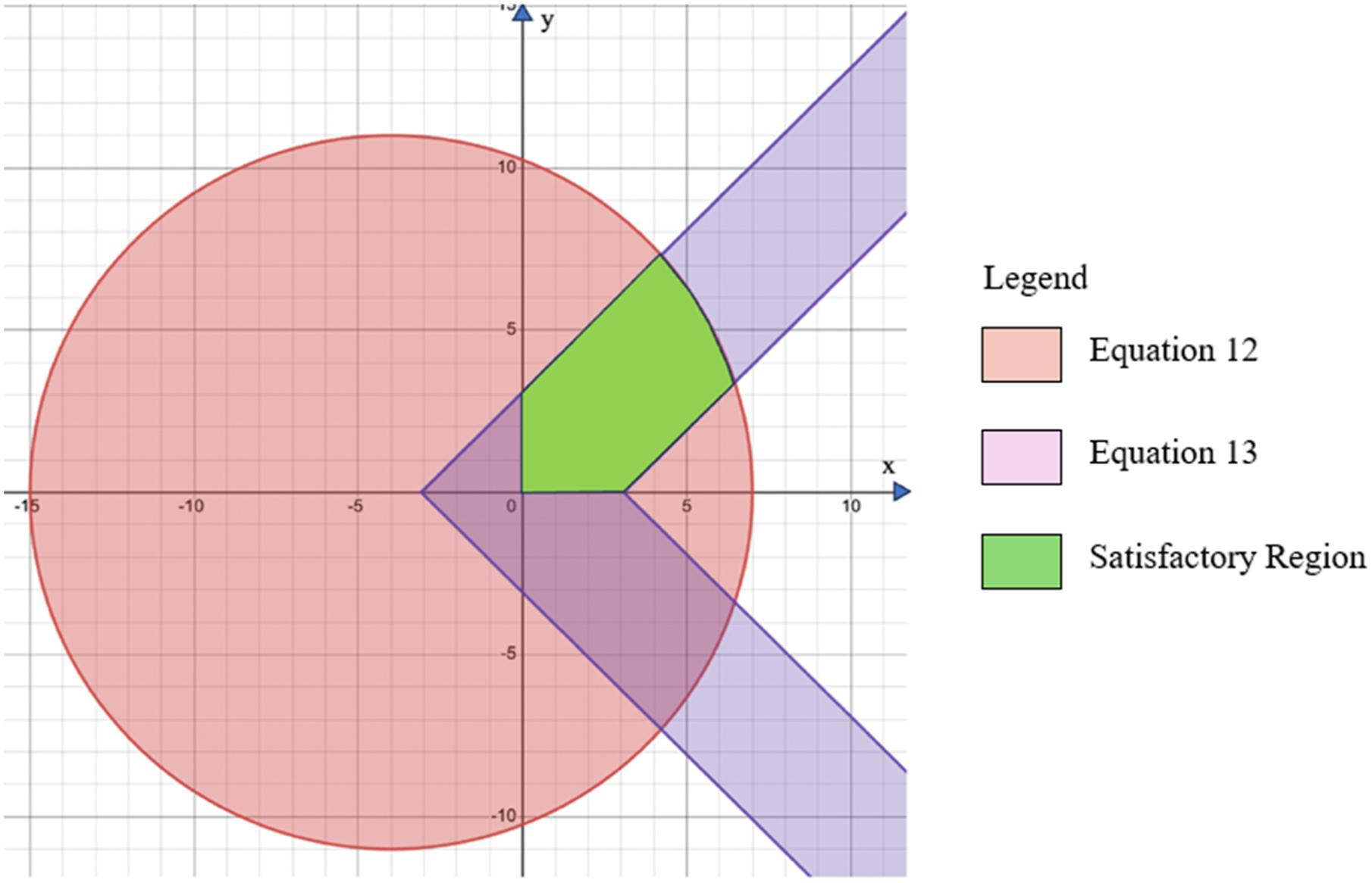
Based on the feasible region, a set of points representing valid combinations of x and y was identified. Equation (14) shows the range of applicable values for y.
Such that the values do not exceed 8.378 ft (2.554 m) and are not less than 3.033 ft (0.924 m) and the total length does not exceed the allotted amount.
Energy consumption
The prototype serves as a small-scale functional model to verify analytical trends. It is not intended to replicate full-scale forces but to capture relative behavior, connection geometry effects, and input-energy trends. Differences between measured and theoretical energy are attributed to frictional and pump inefficiencies inherent to small-scale systems. The experimental results are simply used to validate trends rather than absolute magnitudes of energy consumption.
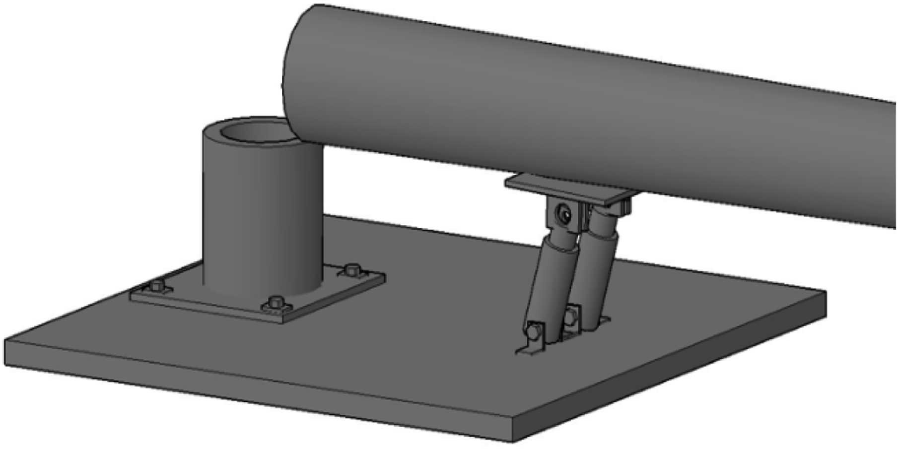
The primary structure consisted of a hollow steel cylinder with a diameter of 12 in. (0.30 m). The cylinder featured a hinge located approximately ¼ of the way from the bottom, enabling the tower section to be raised and lowered using a hydraulic pump, while the base section remained fixed in position. To prevent undesired movement, the base was securely fastened to a wooden board.
The hydraulic pump was positioned on a longer wooden board, which included a metal track on top. The bottom of the pump shaft was equipped with rollers that ran along this track, allowing for adjustment of the pump’s location by sliding it back and forth. This adjustment capability facilitated changes in the stroke angle. The top of the pump shaft was attached to a metal plank with holes, offering further adjustability by modifying the position of this board, which was in turn connected to the tower. This arrangement provided flexibility in controlling the height of the pump and its corresponding impact on the tower.
Properties of hydraulic cylinder used for prototype wind tower.
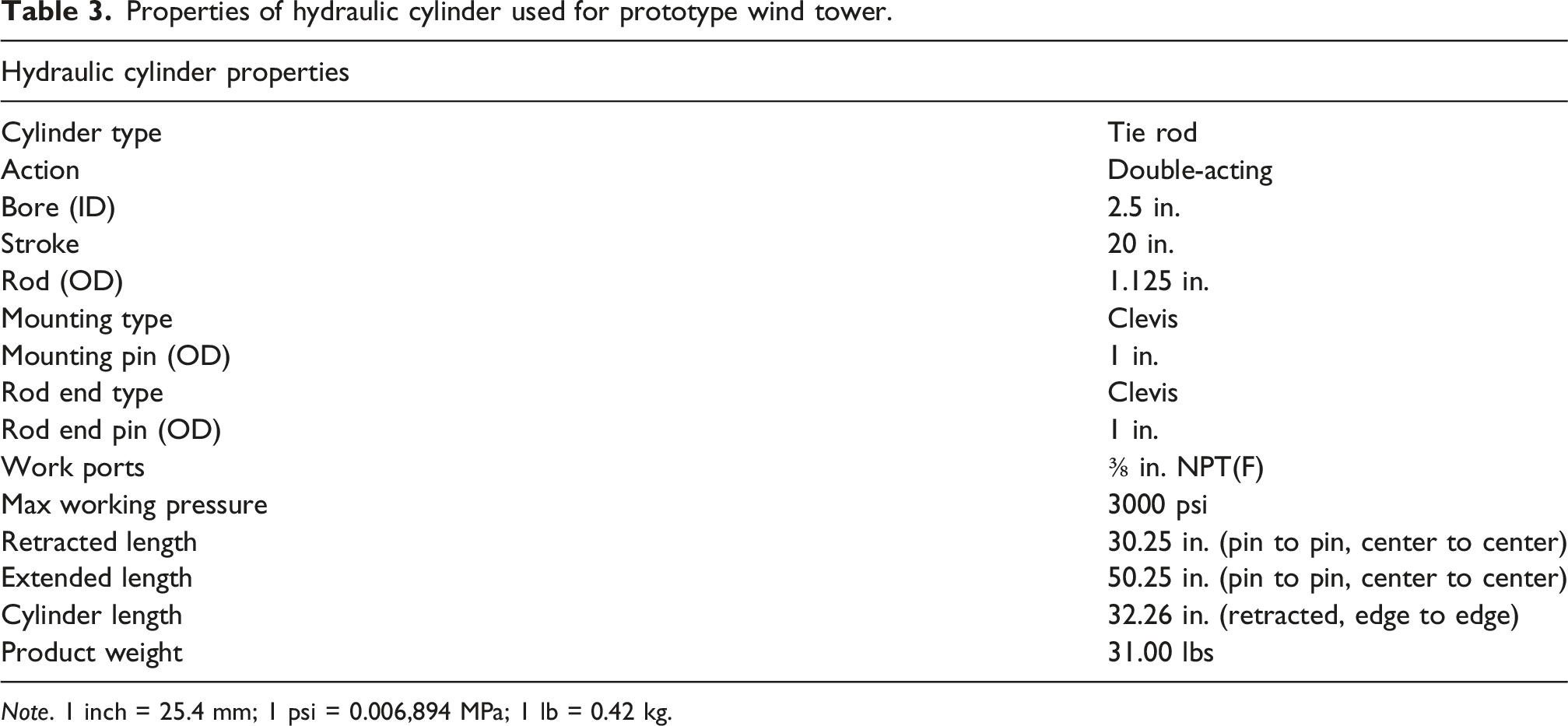
Note. 1 inch = 25.4 mm; 1 psi = 0.006,894 MPa; 1 lb = 0.42 kg.
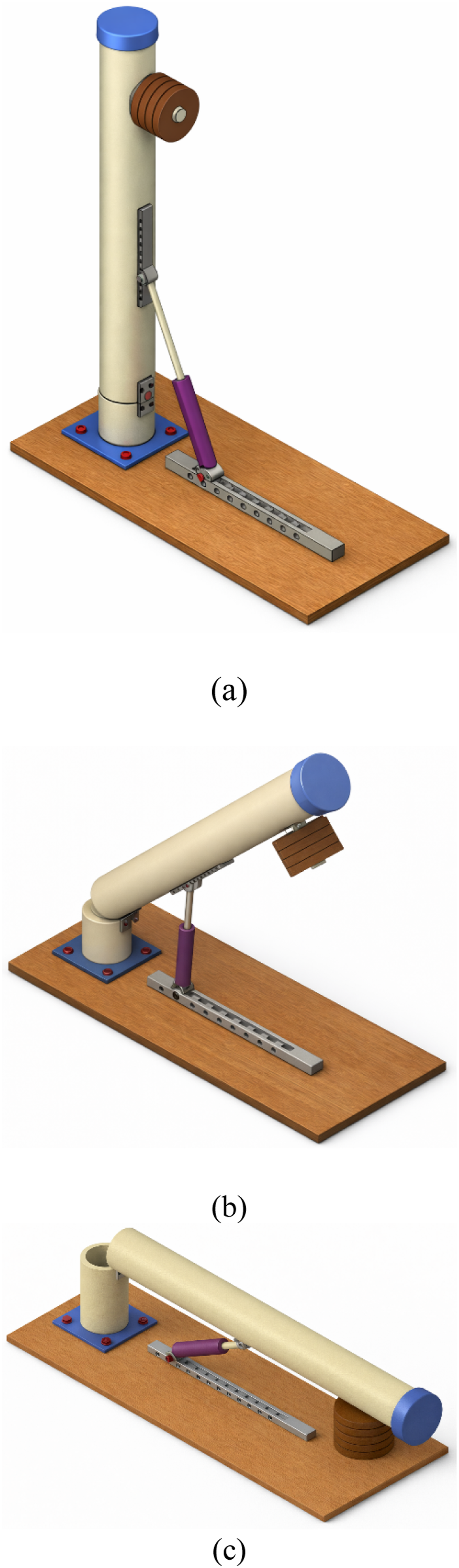
Field investigation would be required to calculate energy consumption by the actual hydraulic erection system. Since that was not possible, the prototype was taken as a reference, and it was assumed that the actual wind tower erection system would follow the electrical energy consumption trend of the prototype. To further validate this, industrial formulas obtained from manufacturers and the maximum load carried were used to calculate the horsepower utilized by the system. Equation (15) (Aggressive Hydraulics, 2023; Flodraulic, 2019) shows the fluid horsepower of a hydraulic cylinder based on pressure produced. Figure 5 presents schematic images of the prototype erection system at different erection angles. Schematic images of the prototype erection system at different erection angles: (a) 0°, (b) 45°, and (c) 90°.
Results
The most effective position for the hydraulic cylinder is determined based on three primary criteria: minimum compressive force in the hydraulic cylinder, reduced energy consumption, and compatibility with the capacity of the selected hydraulic cylinder.
Minimum compressive force generation
Force on hydraulic cylinder varying connection at wind tower “x” constant.
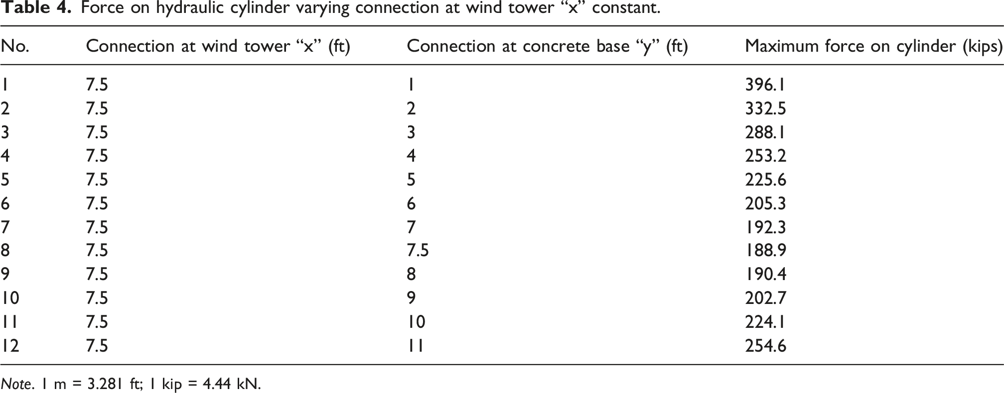
Note. 1 m = 3.281 ft; 1 kip = 4.44 kN.
At steeper angles, (connection at base farther away from the connection at wind tower) the hydraulic cylinder not only has to overcome the weight of the wind tower, but also the moment that is generated on itself. When both values are equal and the hydraulic cylinder is vertical, the moment generated is the lowest and hence, the force produced as well. This configuration represents the minimum-force condition within the evaluated parameter range. Figure 6 illustrates how the force changes when the connection of the hydraulic cylinder is moved in relation to the concrete base. Compressive force on hydraulic cylinder versus connection at base.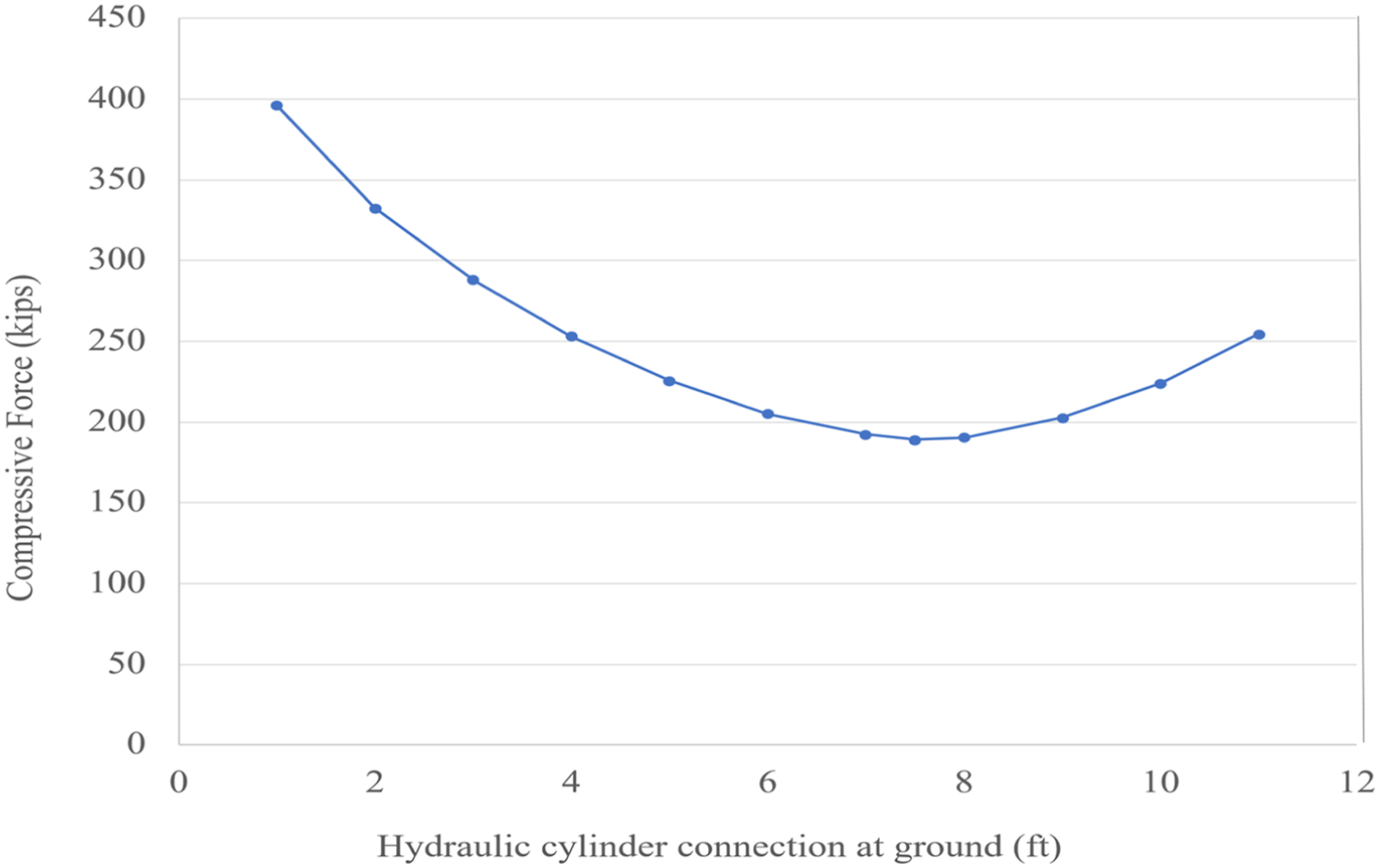
In this case, the values of both 7.5 ft (2.286 m) at the base and wind tower, unfortunately, cannot be achieved. The available space for the hydraulic cylinder connection is very small, and the large bore of the cylinder needed to be in position when the wind tower was at its lowered position.
Force on hydraulic cylinder varying connection at wind tower “x.”
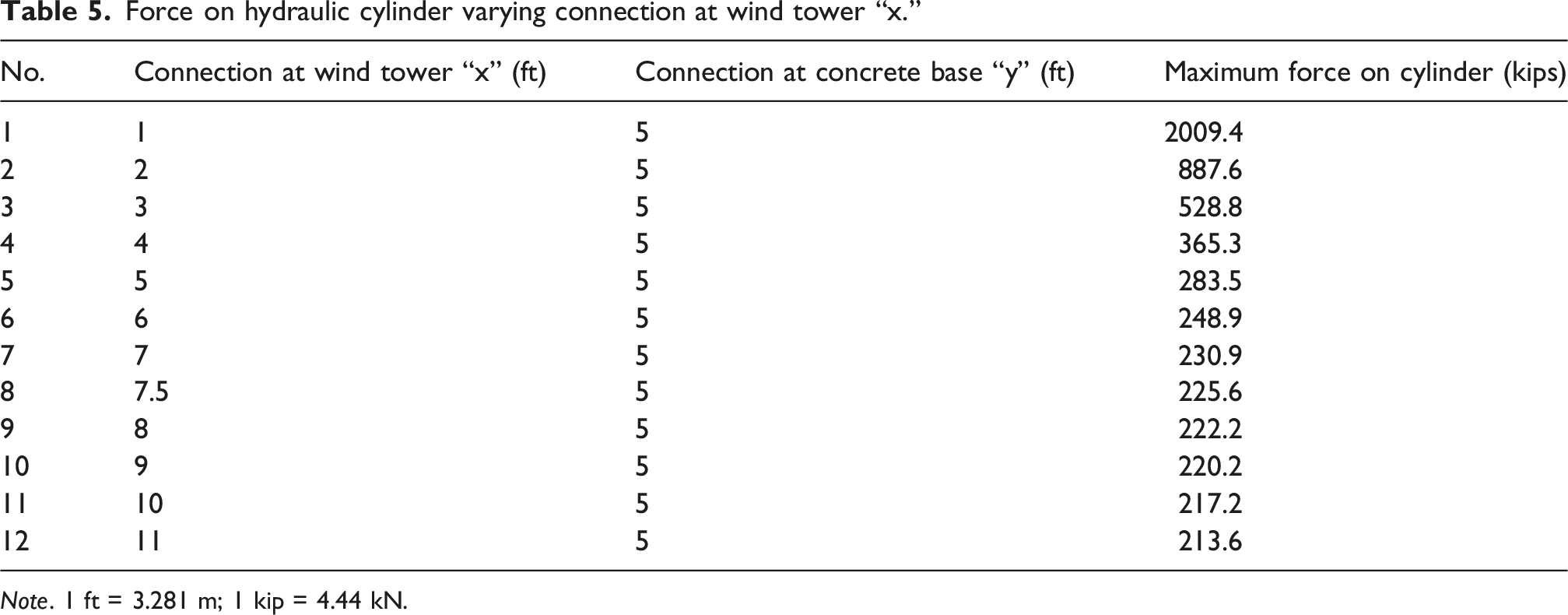
Note. 1 ft = 3.281 m; 1 kip = 4.44 kN.
The selection of a hydraulic cylinder is made easier by this data. Beyond 7.5 ft (2.286 m), there is no significant impact on the hydraulic cylinder. While connections at significantly higher positions may drastically reduce the load impact, economic restraints, transportation and maintenance issues, and unfeasible cylinder design make the connection at a significantly higher level unviable. Figure 7 illustrates a graph representing the force generated while moving the connection of the hydraulic cylinder with the wind turbine tower. Compressive force on hydraulic cylinder versus connection at wind tower.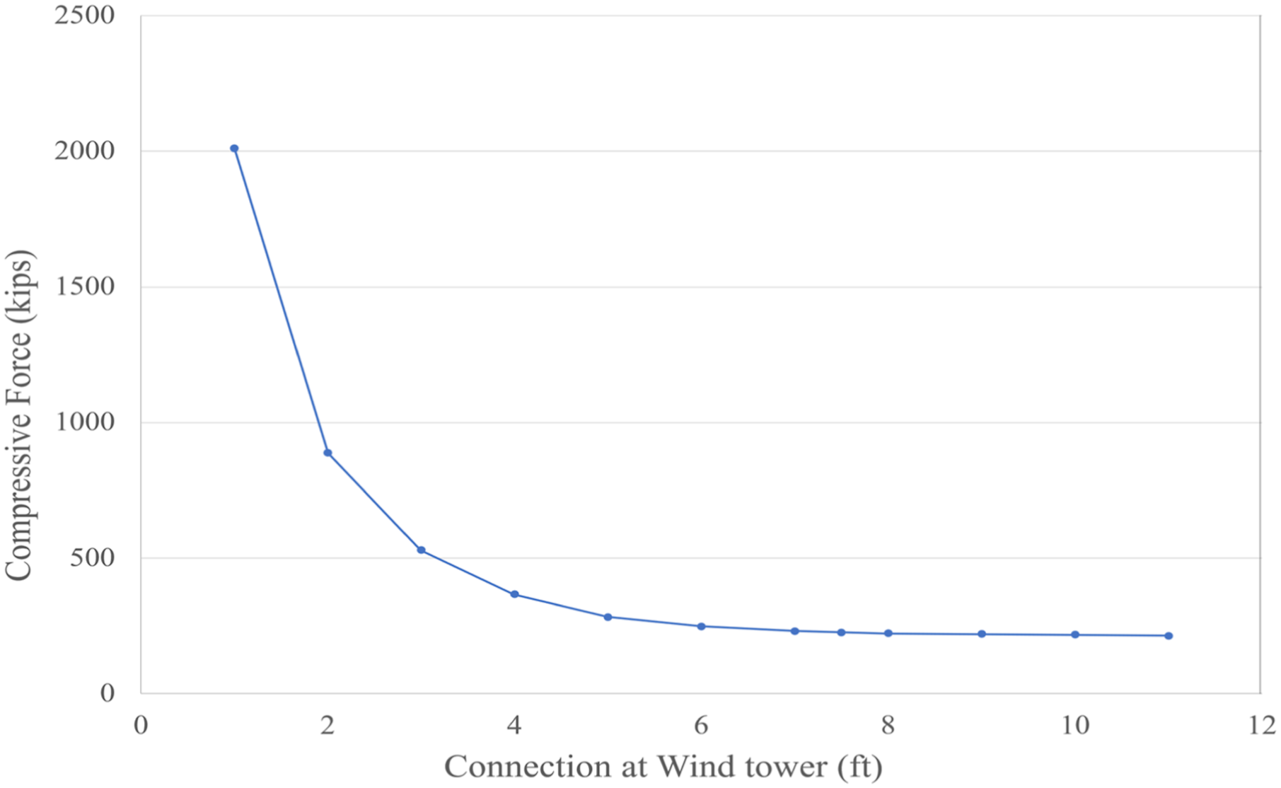
Considering these two results, x = 7.5 ft (2.286 m) and y = 7.5 ft (2.286 m) is the connection point that yields the lowest force on the hydraulic cylinder. However, due to the dimensional constraints of the hydraulic cylinder such a connection is not possible. Hence, the next best possible connection point would be x = 7.5 ft (2.286 m) and y = 5 ft (2.286 m). Thus, the position (x = 7.5 ft, y = 5 ft) represents the optimal connection location because it produces the lowest compressive force within the feasible region while maintaining acceptable erection geometry and a cylinder length that can be accommodated by commercially available hydraulic units.
Hydraulic cylinder capacity
Cylinder capacity check (x = 3.5 ft, y = 5 ft and x = 4.5 ft, y = 5 ft), tower erection.
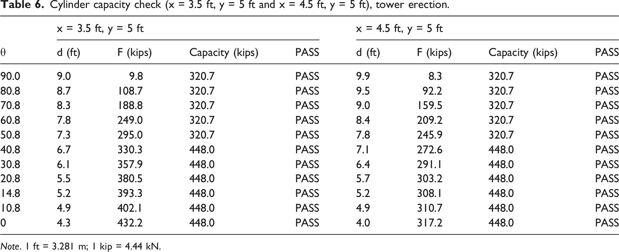
Note. 1 ft = 3.281 m; 1 kip = 4.44 kN.
Cylinder capacity check (x = 6.5 ft, y = 5 ft and x = 7.5 ft, y = 5 ft), tower erection.
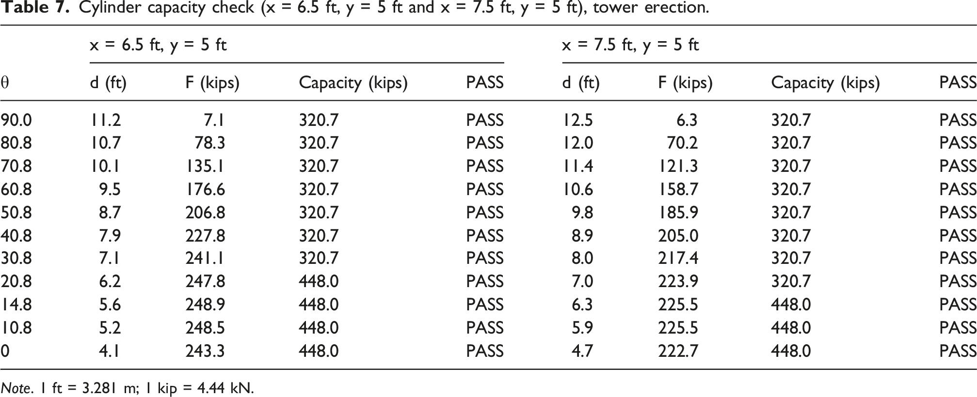
Note. 1 ft = 3.281 m; 1 kip = 4.44 kN.
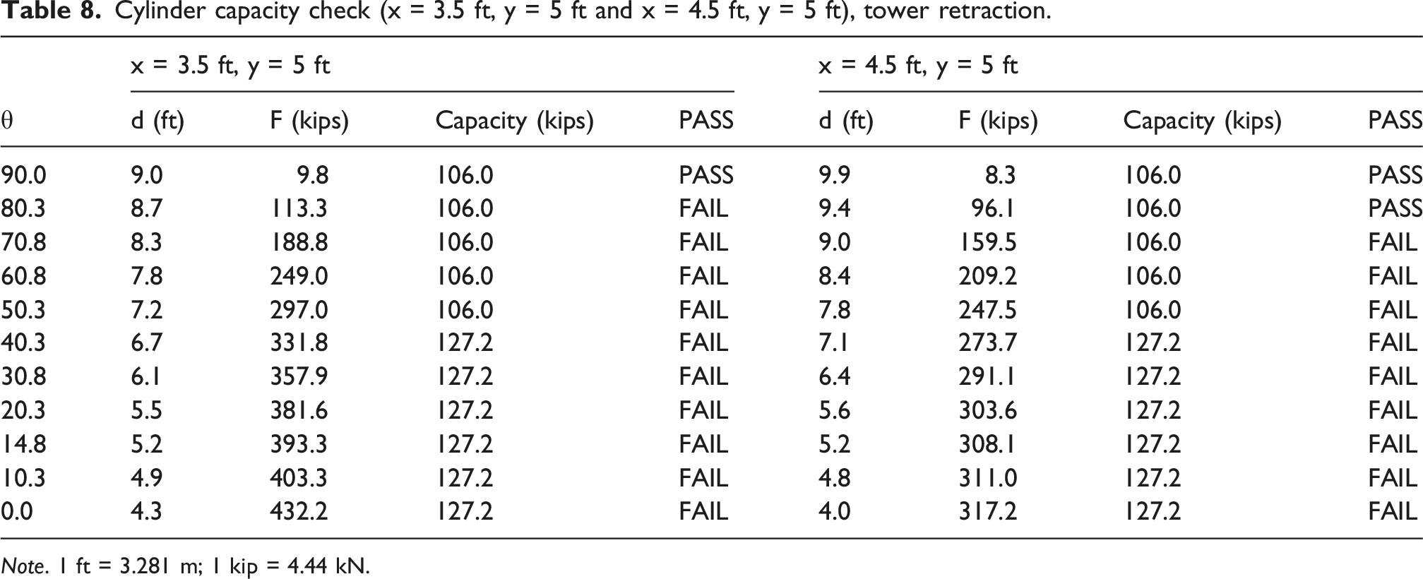
Cylinder capacity check (x = 3.5 ft, y = 5 ft and x = 4.5 ft, y = 5 ft), tower retraction.
Note. 1 ft = 3.281 m; 1 kip = 4.44 kN.
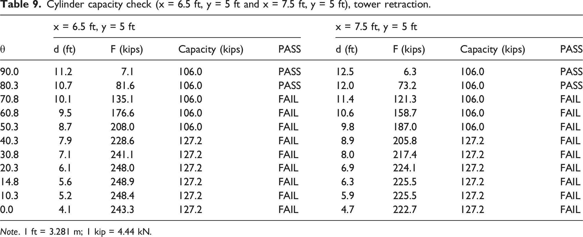
Cylinder capacity check (x = 6.5 ft, y = 5 ft and x = 7.5 ft, y = 5 ft), tower retraction.
Note. 1 ft = 3.281 m; 1 kip = 4.44 kN.
The comparison above shows the two applicable positions for the hydraulic cylinder based on the range calculated earlier. While the tower is being erected, the force provided by the cylinder is sufficient to complete the erection when placed in the optimal position. However, the following tables demonstrate that during the retraction process, the locally available hydraulic cylinder selected is unable to generate enough force capacity to lower the tower back to the ground without failure. This indicates that cylinder capacity requirements differ between erection and retraction, with retraction governing the design in several cases.
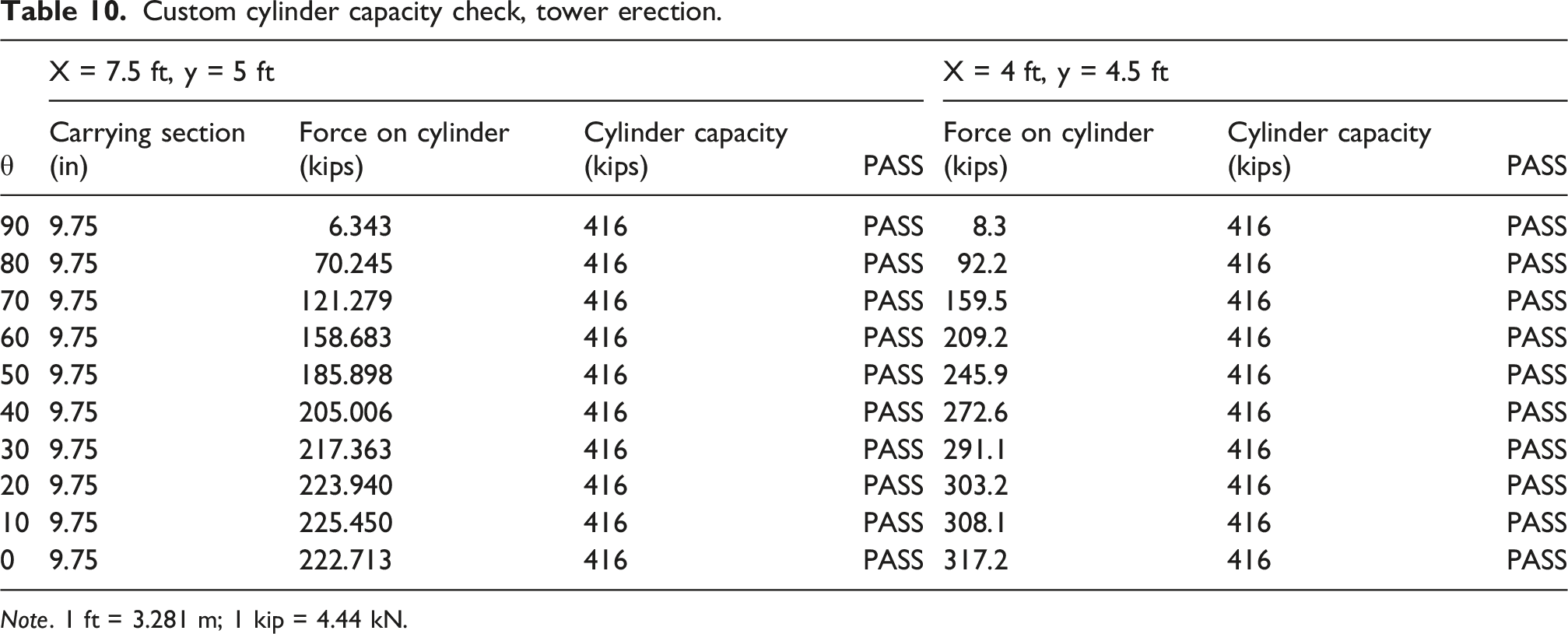
Custom cylinder capacity check, tower erection.
Note. 1 ft = 3.281 m; 1 kip = 4.44 kN.
Custom cylinder capacity check, tower retraction.
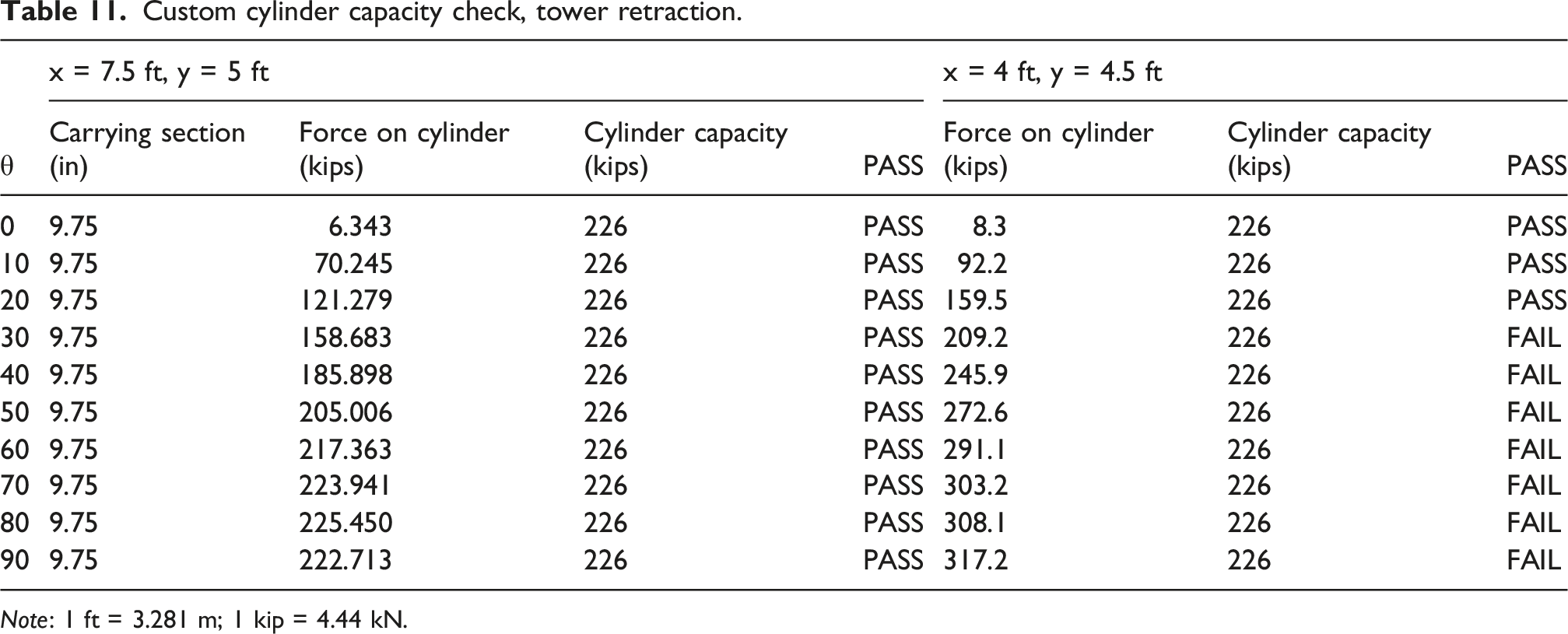
Note: 1 ft = 3.281 m; 1 kip = 4.44 kN.
Energy consumption by hydraulic system
Energy consumed by prototype system based on different approaches.
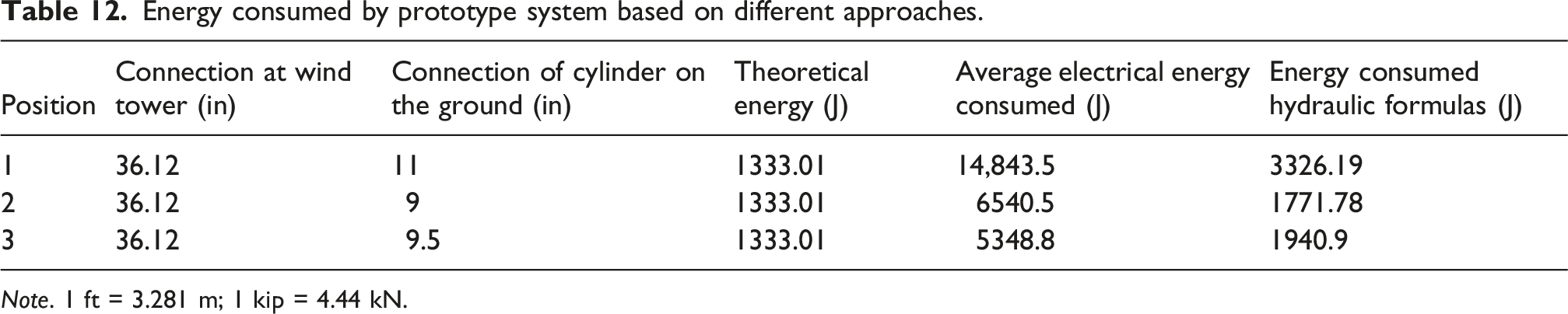
Note. 1 ft = 3.281 m; 1 kip = 4.44 kN.
The position in which the least reaction is generated is responsible for the least energy consumption. The actual electrical energy consumed is assumed to follow the general trend of the prototype. A small-scale hydraulic system has disproportionately higher frictional losses due to seal pressure, pump inefficiencies, and low Reynolds-number effects.
Energy consumed by wind tower erection system based on different approaches.
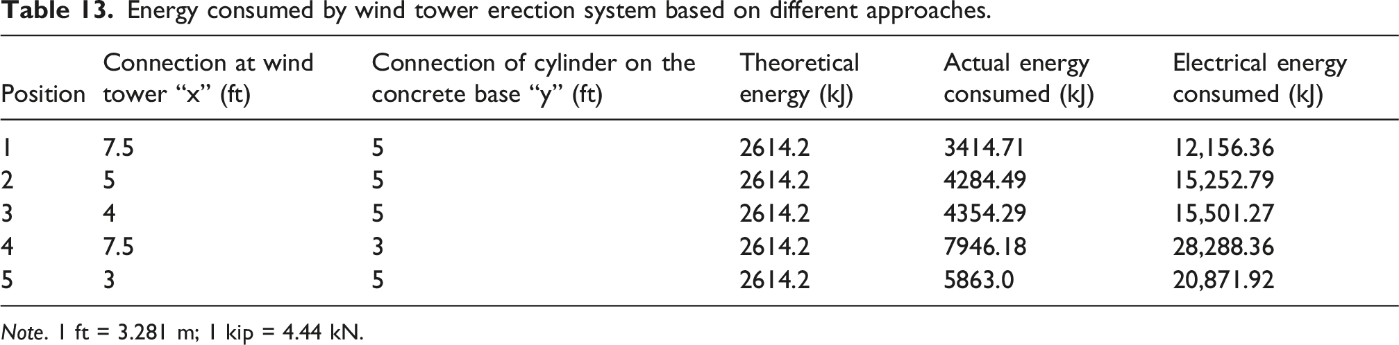
Note. 1 ft = 3.281 m; 1 kip = 4.44 kN.
Conclusions
This study provides important insights into optimizing hydraulic cylinder positioning for wind tower erection. The results are based on a structured parametric evaluation of feasible configurations under geometric and capacity constraints. The findings highlight the critical influence of connection height, the dimensional constraints imposed by hydraulic cylinders, and the limitations of locally available units. The analysis indicates that custom-designed cylinders (similar in size to local ones) offer a practical solution for achieving the required performance. Although future work should include economic evaluation, the results presented here support more efficient and reliable wind tower erection practices and contribute to ongoing development in renewable energy infrastructure. Key conclusions include: (1) The height at which the cylinder connects to the tower substantially affects the ease and feasibility of the erection process. This height is limited by the geometric and dimensional constraints of available cylinders and exceeding these limits can create operational challenges. (2) Locally available hydraulic cylinders were found to be unsuitable for wind tower erection, reinforcing the need for cylinders specifically designed or customized for this application. (3) Custom hydraulic cylinders, with dimensions comparable to locally available units, can be fabricated to meet the performance requirements and improve the safety and efficiency of the erection process. In practical applications, hydraulic erection systems should be supplemented with mechanical locking mechanisms or redundant supports to ensure stability during erection, lowering, and maintenance operations. (4) For the examined system, the optimal connection occurs at the horizontal distance of 7.5 ft from the tower and the vertical distance of 5 ft from the base, satisfying geometric constraints and yielding.
This study is subject to simplifying assumptions, including idealized loading conditions, use of a scaled prototype, and neglect of dynamic effects and friction losses; results may vary for other geometries or field conditions. These limitations should be considered when applying the findings to full-scale wind tower systems. Additionally, although dynamic effects and transient loads may occur in practice, hydraulic tower lifting is typically performed as a slow, controlled operation with negligible acceleration. Accordingly, static analysis provides an appropriate first-level approximation of the forces acting on the cylinder during the erection process. Transient wind loads and dynamic amplification during erection were not explicitly considered and should be managed in practice through controlled operating procedures and favorable weather conditions. Future work should incorporate dynamic effects, wind loading during erection, and numerical modeling approaches to further improve the applicability and predictive accuracy of the proposed framework.
Variations in tower height, mass distribution, and geometric proportions may influence the optimal cylinder positioning and structural response during erection. Therefore, the direct generalization of the current results to larger or substantially different tower configurations should be made with caution. Future studies should investigate dimensional scaling effects and broader parametric variations to improve applicability across diverse wind tower systems.
Footnotes
Acknowledgments
The authors gratefully acknowledge the financial support provided by the NASA Connecticut Space Grant Consortium (CTSGC). The authors also acknowledge the University of New Haven for providing facilities and resources used in conducting this research.
Author contributions
Anbesh Rawal: Data curation, Formal analysis, Methodology, Writing review & editing. Bhupesh Chand: Formal analysis, Methodology, Writing review & editing. Byungik Chang: Conceptualization, Methodology, Project administration, Supervision, Writing review & editing
Funding
The authors disclosed receipt of the following financial support for the research, authorship, and/or publication of this article: This work was supported by the NASA Connecticut Space Grant Consortium (CTSGC) Faculty Research Grant under NASA Award No. 80NSSC20M0129.
Declaration of conflicting interests
The authors declared no potential conflicts of interest with respect to the research, authorship, and/or publication of this article.
Data Availability Statement
Some or all data, models, or code that support the findings of this study are available from the corresponding author upon reasonable request.