
Abstract
The growing need to recover and digitally represent heritage infrastructure has led to the challenge of choosing different Building Information Modeling (BIM) platforms that will be used to manage the implementation of the semi-automatic design and reconstruction processes of reverse engineering modeling. The approach to the integrated management of information derived through Heritage-BIM (H-BIM) has been applied to Via del Duomo, one of the main roads in the old town of Naples, Italy. During preliminary inspections of the construction site it was possible to acquire geometric features and pavement/subgrade information, as well as to conduct a photographic survey, with 1,618 photographs collected. Subsequently, the acquired data were processed, using different BIM-based tools, to obtain the 3D mesh; objects were then converted from pure graphic solids into parametric entities by proposing a specific algorithm. Then a library, with the inclusion of all the possible stone paving package alternatives, including all the structural and stress-deforming characteristics such as Young Modulus (E), Poisson coefficient (n), and Safety factor (SF), was created. In this way, it is possible to associate to the generic element the optimal pavement package solution, depending on different construction contexts. As preliminary result, a dynamic model that updates its information package and modifies the output of the analysis every time the data worksheet is integrated with new collected results is proposed for further pavement management operations evaluation.
Roman road pavements have defined and materialized the communication routes of Europe, with consequent scientific attention paid to the enormous cultural, aesthetic heritage, and historical value of Italian streets.
The stone pavement was already part of the largest and most wonderful expression of the power of Roman construction, and of the rarest and most admirable implementations of the Renaissance age, up to the extensive installations of the post-unification period. It has represented for centuries the conceptual reference for the physical constitution of durable and stable roadways, especially in rich urban contexts: the unconscious and irreplaceable background of the concept of an Italian city.
The immense road heritage of stone road pavements, starting from the capital city, has never been the subject of wide-ranging policies aimed at their enhancement in recent times. They are often abandoned to degradation, without adequate provision, uncoded, and not preserved within generational transition investigation and maintenance methods. It is notable that, to date, there is a lack in the literature of rational calculation methodologies for stone pavements, and of tools for analyzing road surfaces to assess the compatibility between roads in high-quality areas and the needs of traffic and collective mobility.
It would be desirable that this lack of technical knowledge about stone pavement calculation be scientifically filled by the country that, more than any other in the world, should invest in the great heritage of the historically valued paved roads that distinguish it, and that constitute a recognized paradigm.
Around the fascinating pavements of the Roman road networks, which are characterized by very different construction and constitutive features, the authors have put in place advanced geometric survey strategies and graphics and physics 3D restitution techniques.
The digitization of data relating to historical heritage consists of the creation of a representative virtual model—a virtual copy—and constitutes a database of information in the best way. The aim is to preserve the cultural significance of the artistic asset and to define intervention strategies in an optimal way. In this sense, a Building Information Modeling (BIM) model could be a good solution for the management of this type of information, being able to incorporate an asset’s quantitative and qualitative data in a structured way, which can be easily extracted if necessary ( 1 ).
Literature Review
The complex modeling of cultural heritage through commercial BIM software leads to the consideration of the concept of Heritage-BIM (H-BIM) ( 2 ). H-BIM indicates a new way of modeling, which pursues the modeling of architectural elements according to artistic, historical, and constructive typologies. It is considered to be a special library of BIM parametric objects that was specifically designed to preserve and manage cultural heritage within the general framework of “smart heritage” ( 3 – 5 ).
H-BIM offers very versatile solutions for modeling and managing information relating to existing and heritage projects. It can be used as a documentation and management tool for conservation work, retrofitting, renovations, and analysis. It can also be used as a research tool for documentation and interpretation of historical projects and representation of changes to the infrastructure over time ( 1 ).
The H-BIM process involves a reverse-engineering solution starting from relevant data ( 6 ). Starting from these data, a library of parametric objects that represent the different components of infrastructure can be created ( 7 ). These modeled elements will then be merged to obtain a unique virtual representation of the historical building ( 8 ).
Nowadays, many researchers explore different methods for documentation, management, and sustainability of cultural heritage; these have become an interdisciplinary approach to the development of the culture ( 9 ). Bianco et al. ( 10 ) proposed the creation of a web platform with an information system on cultural heritage. The system would allow different access levels: people who can edit data and people who can only view it. This platform should be in line with BIM interoperability principles, allowing users to access the three-dimensional model and data tables.
Geometric shapes can be created in the BIM model manually, semi-automatically, or automatically, based on the point cloud or the triangulated mesh ( 11 ). The manual method consists of modeling shapes and volumes on the trace of the point cloud. Semi-automatic modeling methodology consists of resorting to libraries of architectural components of historic buildings which, through algorithms, can be combined automatically to generate facades and models. Then the model is redefined and adapted based on the geometric survey performed with a laser scanner or photogrammetry.
For example, Monna et al. ( 12 ) proposed a 3D acquisition workflow based on structure-from-motion. From the 3D geometry of objects of interest, elevation raster maps were produced by projection on four sides of the stela. These digital elevation models are then tested using algorithms based on differential geometry, sky visibility, and local morphology, the general principles of which are briefly exposed.
Fryskowska and Stachelek ( 13 ) proposed an assessment of geometrical content of 3D models for H-BIM without reference measurements and independently of the data-acquiring method or point cloud resolution. The point cloud was obtained by terrestrial laser scanning. Then, selected elements of cultural heritage structures were modeled with the use of dedicated BIM software on the basis of point clouds with different geometric parameters. 3D models were developed on the basis of point clouds in all resolution variants, both with the manual and the automatic method.
Once the geometry of all the components of the product has been created and the semantics defined, it is possible to add other relevant data and information, always in a structured way, by associating them with the correct BIM element ( 14 , 15 ). By properly preparing the data, the subsequent extraction of information is facilitated, and the data can be obtained correctly for any subsequent analysis such as structural calculations, lighting engineering, management of the premises, and so forth. ( 16 ).
BIM applications are directly realized using an internal database of 3D groups of architectural elements (Family) to accommodate a variety of information (Properties). This ability allows users to change the morphological and typological aspects of each element before/after their generation through tools that update their physical quantities (Parameters) such as height, width, scale, and their physical and thermal characteristics (for example, types of materials, stratigraphic information). At the same time, the BIM application can create links and intelligent interactions with other architectural elements that make up the model by increasing the control of the generation and management of the model ( 9 ).
There are currently many BIM platforms used by experts to perform the modeling, virtual visualization, and management of the integral and incremental knowledge of architectural heritage. However, it is important to note that the libraries and tools of the BIM platforms focus on the design and construction of new buildings with simple, regular, and standardized objects ( 17 , 18 ). For this reason, the virtual and detailed reconstruction of cultural-historical heritage has revealed some limitations of BIM platforms, such as the unavailability of historical parametric object libraries and the lack of tools for managing complex, irregular, and uncertain shapes that are obtained from point clouds.
However, the virtual reconstruction procedure of historical-cultural heritage is not an easy task, because the objects to model consist of components whose heterogeneous, complex, and irregular characteristics and morphologies are not represented in the BIM software libraries ( 2 ).
Aims and Methods
The aim of the research is to present a methodology (see Figure 1) for creating a digital parametric model of an existing historical pavement, and to design an algorithm able to indicate the optimal solution as pavement package, including all the structural and stress-deforming values, to use in different construction contexts.
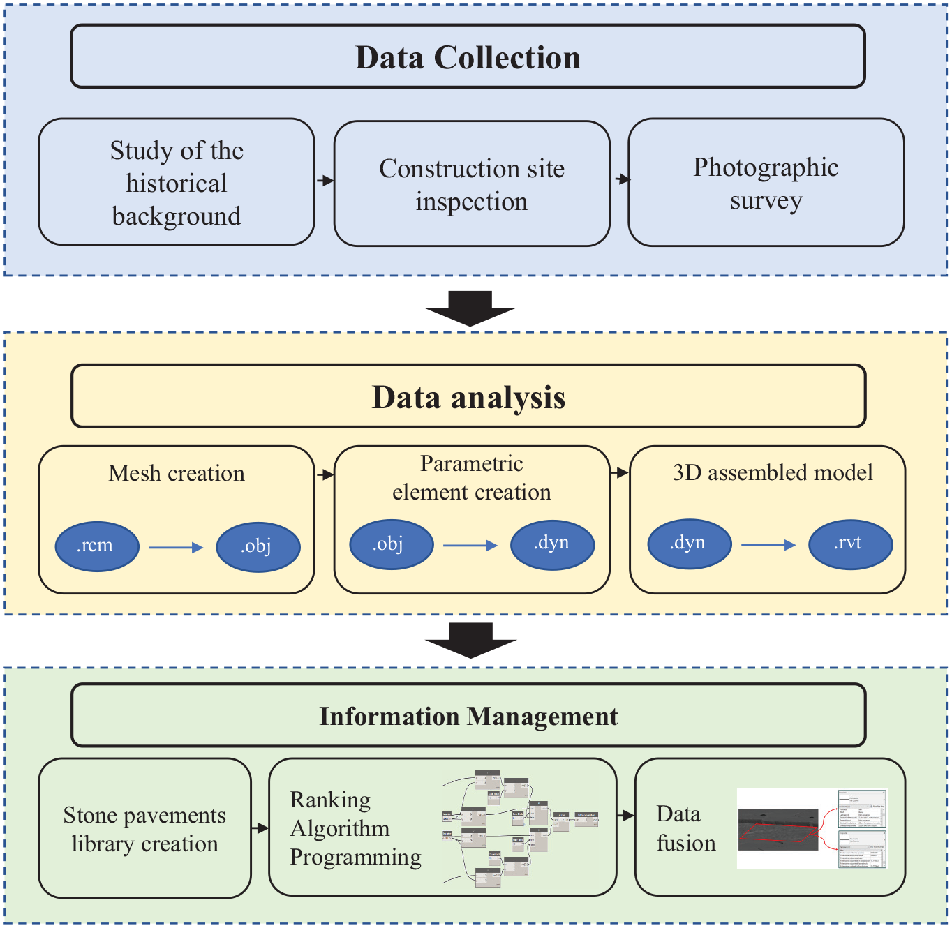
Methodology overview.
These steps can be carried out semi-automatically or fully automatically through the advances added to BIM platforms, as well as the new algorithms of object recognition.
Via Duomo in Naples was chosen as the case study for several reasons: (a) historical and cultural, as the road is a reference point for the city’s tradition and tourism; (b) functional, as it is suitable for both pedestrian and vehicular flows; (c) operational, as the site is currently under restructuring works, allowing the possibility of data acquisition in relation to documents, conversations with work teams, and photographic survey.
Data Collection
For the purpose of the study, the historical context is briefly presented, followed by the retrieval and study of all reports on the site characteristics such as stratigraphy, materials processing techniques, and their physical-mechanical characteristics; then, in the absence of data from aerial photogrammetry or drone survey, an on-site photographic survey was carried out by means of a camera as starting point for the creation of a BIM model.
Historical Background
With the foundation of the colony of Neapolis, the current Via Duomo represented one of the secondary arteries oriented in a north–south direction which, intersecting orthogonally with other main ones in the east–west direction, formed a network called hippodamea by its creator Hippodamus from Miletus.
This schematic had been in place during Roman times and remained unchanged over the centuries, including the restricted width of the street (see Figure 2a), until restoration works were undertaken in the second half of the nineteenth century, resulting in roads that are now suitable for both pedestrian and vehicular flows (see Figure 2b).
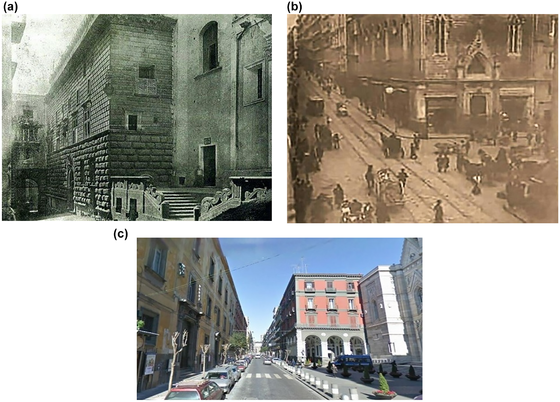
Via Duomo: (a) pre-restoration 19th century, (b) post-restoration 19th century, and (c) current conditions.
Currently, Via Duomo falls among the sites affected by the Project “Historic Center of Naples, UNESCO site enhancement,” which is part of the regional operational program named “CAMPANIA 2007-2013” approved by the European Commission (see Figure 2c). The one hundred-million-euro project’s objective is the requalification of part of the historic center, restoring the urban continuum avoiding the fragmentation caused by isolated buildings, preserving the existing heritage, orientated to relaunch tourism and historical and cultural activities.
The project of the sub lot in Via Duomo foresees the replacement of the existing porphyry cubes for the road pavement because of maintenance and functional difficulties, with the installation of Vesuvian lava rock paving stones with a minimum thickness of 18 cm, as well as the widening of the sidewalks and the inclusion of specific paths for people with visual impairments.
Via Duomo Construction Site and Herculaneum Plant Inspection
Any approach to the conservation and functional and structural rehabilitation of historically significant stone pavements must include an informed preliminary analysis of construction criteria ( 19 , 20 ).
The flagstone “basolo” is used for paving; consequent to the current Italian Standard on extractive activities ( 21 ), which excludes quarrying from Vesuvian territory, this derives from other requalification works carried out in a nearby area. These recycled materials, before paving, were first transported to Herculaneum plant.
After having obtained the necessary authorizations, it was possible to access the Herculaneum plant and Via Duomo construction site and to gain a better understanding of the stone element’s material and the techniques used to install it. At the Herculaneum plant (see Figure 3a), the mentioned recycled materials underwent manual regeneration using a “puntillo” technique (see Figure 3b).
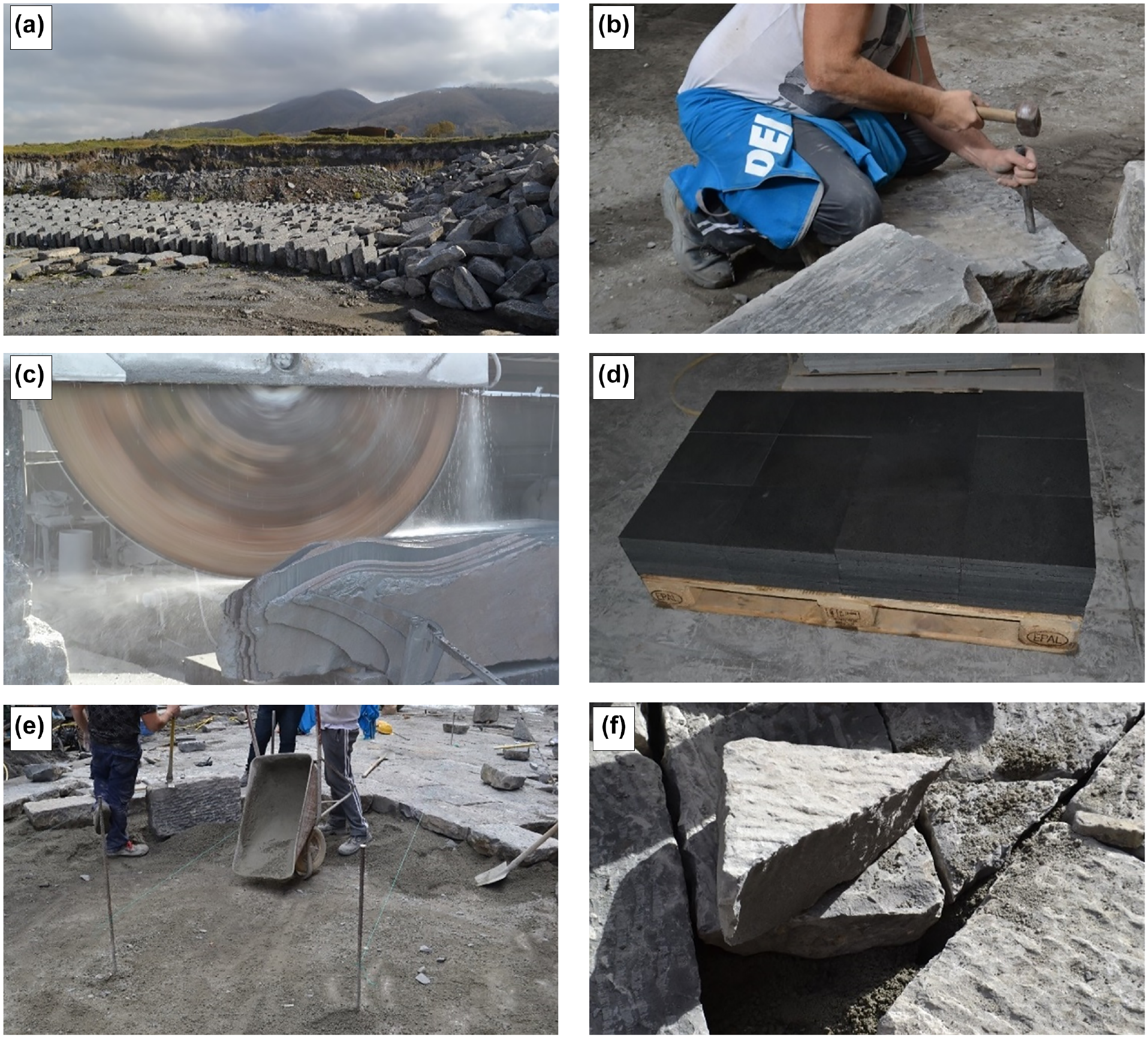
Paving activities: (a) Herculaneum plant storage, (b) “puntillo” technique, (c) metal saws, (d) sidewalk end product, (e) on-site stone placement, and (f) voids filling.
For urban furnishing elements and sidewalks, rocks of volcanic origin were used that have the same mechanical characteristics as the Vesuvian counterpart, but differ slightly in pigmentation, darker in the insular one. The rocks are cut into slabs according to the required thickness, using circular metal saws (Figure 3c), and then the end product (Figure 3d) is obtained by modeling with precision instruments and, in some cases, finished by hand.
Then, the elements are transported to the Via Duomo construction site where they are assembled and positioned, after the scarification of the existing porphyry cubes, and the installation of a first layer of geotextile, a reinforced concrete slab, and a layer of coarse sand and hydraulic binder lodging.
First, the elements constituting the curbs are placed, and then, knocking with a mallet, the regenerated “basoli” (Figure 3e), fixing the paving stone above the bedding layer. On the end of the pavement, the voids are filled with shaped rocks through the beating of a mallet on a wedge (Figure 3f), and the joints are sealed with liquid cement mortar. Finally, the roadway is completed and the remaining elements placed, such as sidewalk, crossing platforms, urban furniture, and so forth.
Photographic Survey
Although the current development of computational intelligence does not allow for complete automation, the combination of photogrammetry with computer vision (basically incorporating Structure for Motion algorithms) is beginning to provide accurate results in 3D modeling in cultural heritage ( 22 ).
Free and online access to a multitude of quality photographs is becoming an incomparably fast, cheap, and realistic way of capturing reality to virtually reproduce artifacts and buildings ( 23 ). This is why an increasing number of software tools are easily found to reconstruct 3D models from photos as automatically as possible.
On-site photographs were collected using a standard camera, capturing the desired target at the same distance, and in addition, making three different circumferences around it: one on the street level; one at half height to have an angle of 45°; and one overhead to capture the target almost orthogonally (Figure 4a). In this step, it is necessary to take photos around the object, changing the inclination and the point of view from time to time. It is essential not to move the subject under examination during the acquisition, as the processing software also recognizes the surrounding environment. Multiplying the number of shots from different angles is generally recommended, as this will increase the number of matching features and redundancy ( 24 ).
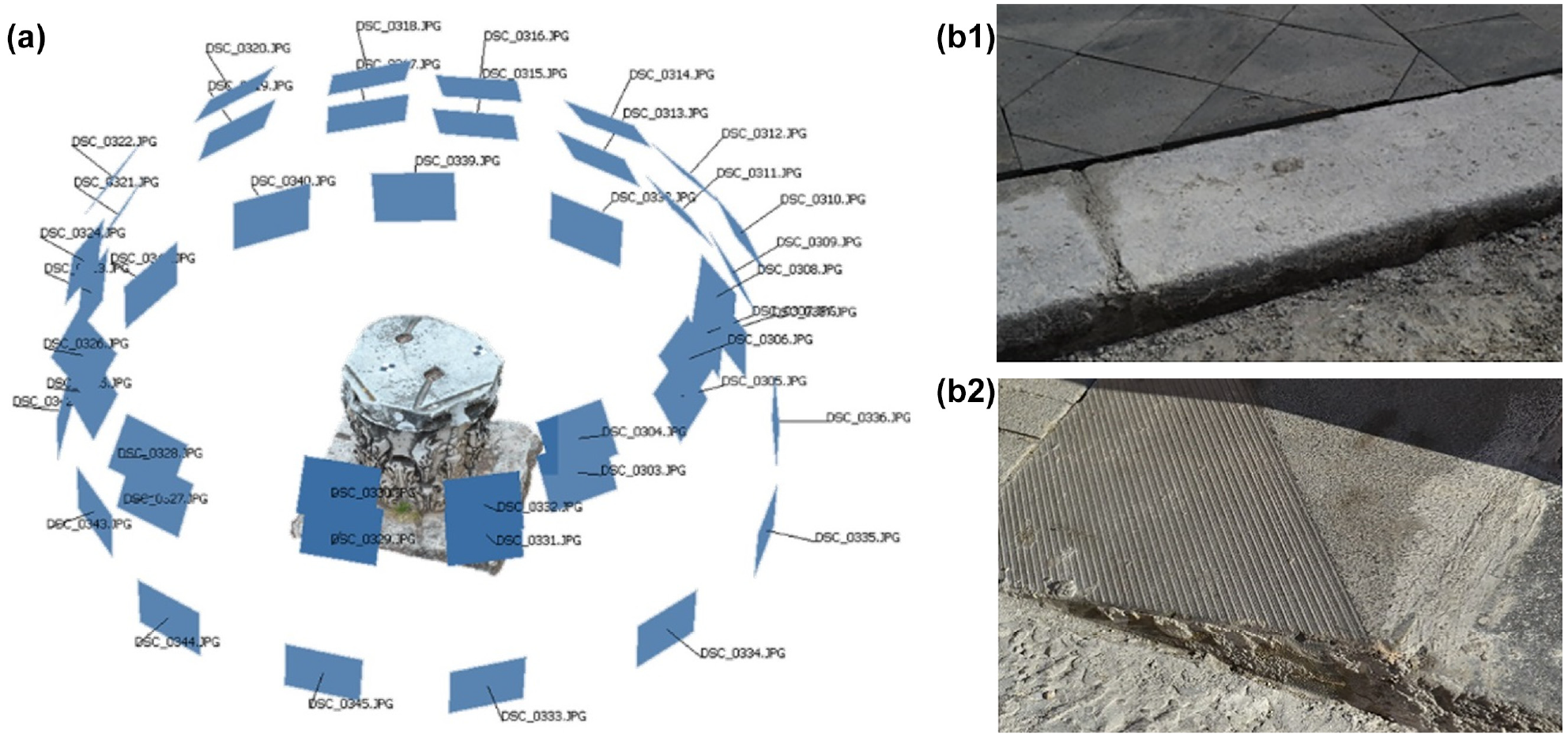
Photographic survey: (a) camera placement and (b) photographs sample.
Subsequent photographs must overlap by at least 70% to ensure continuity in the pigment’s resolution. Furthermore, each analyzed element was captured for a minimum of 20 and a maximum of 100 frames.
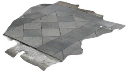
At the end, 1,618 photographs (photograph sample in Figure 4b) were collected, as a starting database for the 3D meshes reconstruction process. To obtain geometrical, topological, and semantic attributes, it is necessary to produce 3D geometric models or parametric objects. This 3D modeling can be described as a reverse engineering process.
Data Analysis
Mesh Creation
Mesh interprets the complexity of the shapes through the union of points through polygons based on different algorithms. This type of model is equivalent to a sparse representation of a point cloud in the space ( 25 ).
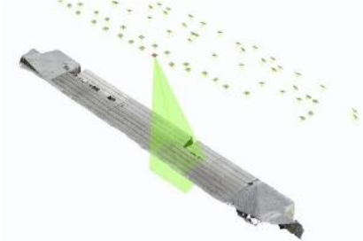
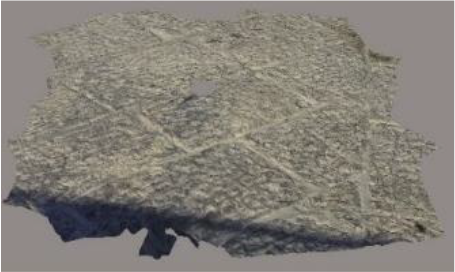
Data collected were processed to investigate the potentialities of two BIM-based tools: Bentley ContextCapture and Autodesk Recap Photo. Both platforms perform a triangulation and mesh reconstruction, or rather a partition of a surface in a mesh of cells, starting from the photogrammetric surveys. The main features detected are highlighted in Table 1.
Main Features of Bentley ContextCapture and Autodesk Recap Photo
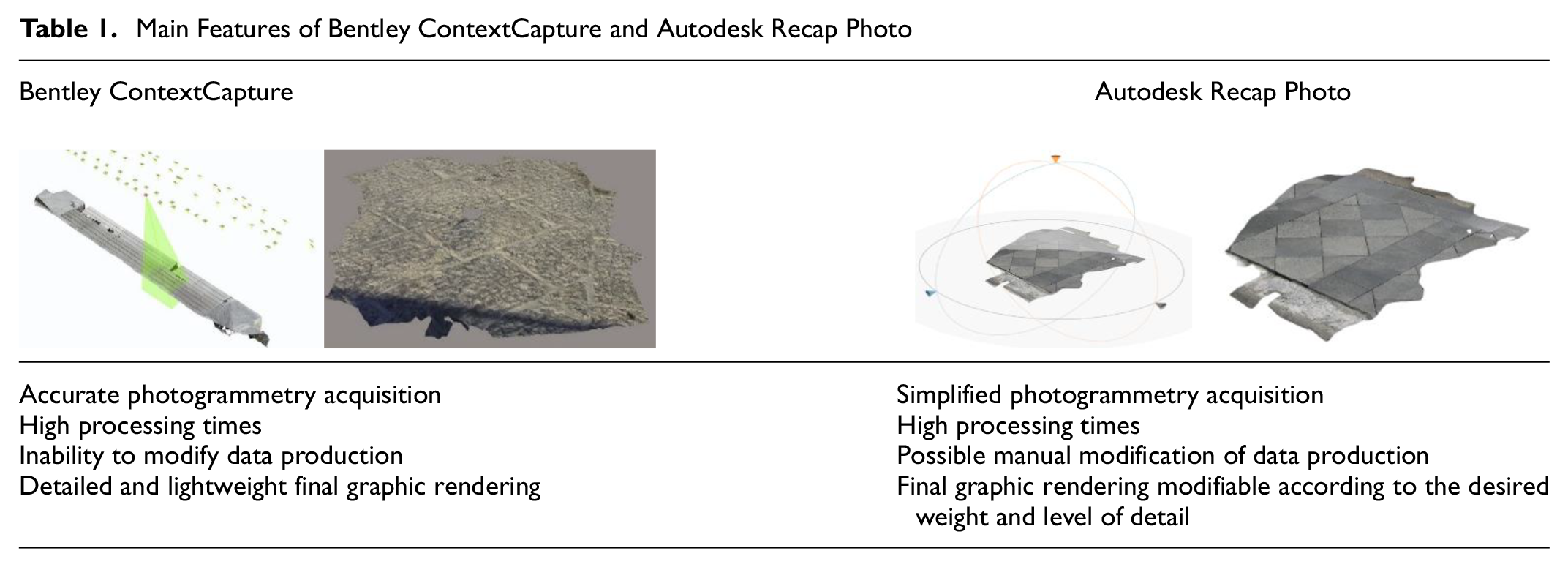
Recap Photo presents a simplified mesh extraction process as the aerotriangulation, reconstruction, and production processes are automatic when the images, videos, or both are added on the platform.
The level of detail of the mesh is strongly influenced by the number of frames; the greater the number of photos, the greater the detail of the element.
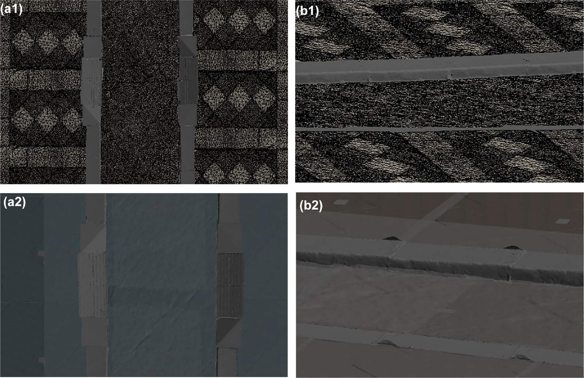
In the case of inaccuracies or the presence of holes during mesh reconstruction, it is possible to fill these voids with new triangles chamfered according to requirements. Figure 5 shows a generic mesh creation result.
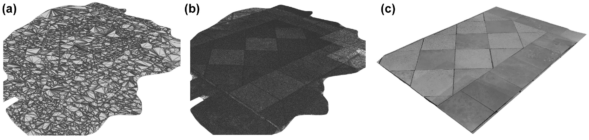
Mesh creation: (a) pre-decimation, (b) post-decimation, and (c) final result.
Parametric element creation
The parametric element was created using Dynamo, a plug-in included in Autodesk Revit. Dynamo is an open-source visual programming language (VPL) that operates through the manipulation and connection of graphic entities. In this way, is possible to create complex forms, analyze solutions, and automate procedures.
Dynamo uses “nodes,” which have the function of executing instructions, and “links,” with the function of making sequential operations. Dynamo nodes can have different functions but are basically divided into three main categories: creation, modification, and query nodes. In addition, each node, except for purely input ones, has one or more input ports on the left, indicating the characteristics to be entered to proceed, and one or more exit ports on the right for final rendering.
Then, using the workflow shown in Figure 6, it is possible not only to obtain the real shape of each single element, but it is also possible to add its related parameters.
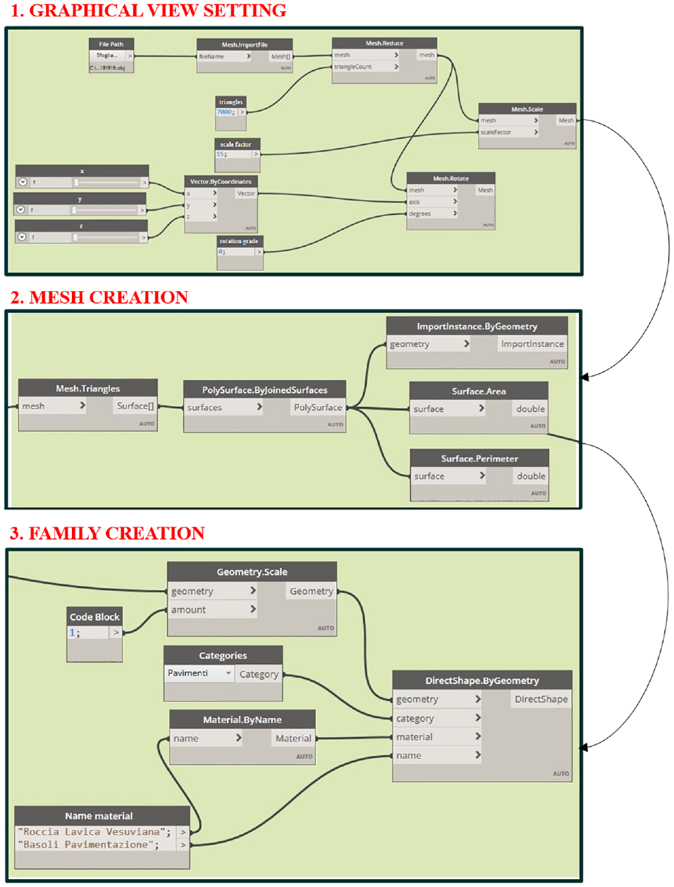
Dynamo workflow for creating parametric elements.
First, the mesh model (.obj format) was uploaded in Dynamo (see nodes “File path” and “Mesh.ImportFile” in Figure 6). Then, after the reduction of the mesh to the number of triangles that achieved the desired compromise between geometric detail and computing time, the mesh was scaled and rotated according to x, y, z coordinates (see nodes “Mesh.scale” and “Mesh.rotate” in Figure 6).
Once the mesh is defined, the node “Mesh.Triangles” was used to convert each triangle of the mesh into a surface. These triangular surfaces were then joined and the output surface was imported in Revit environment (see “PolySurface.ByJoinedSurfaces” and “ImportInstance.ByGeometry” in Figure 6).
Last, a specific family was created (see “DirectShape.ByGeometry” in Figure 6) for the stone elements through four inputs: the geometry (created surface), the category (pavement), the material, and the family name, which have been assigned by the authors.
A preview of a curb element, as result of the mentioned procedure, is shown in Figure 7.
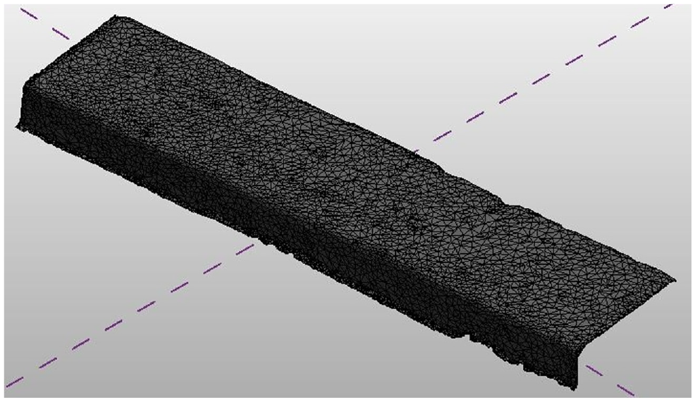
Element preview in Dynamo.
Single meshes are then imported in Revit, converting .dyn format to .rvt format.
The choice of using Revit, mostly used for vertical structures, instead of Civil3D, a well-known BIM-based tool for infrastructures, is to be found in the nature of the type of element to represent. Indeed, the representation of the stone pavement element goes closer to the “floor family” implemented in Revit and not included in Civil 3D.
Revit recognizes the meshes as individual surfaces independent of each other; therefore, through a specific node type, it was possible to join the meshes in a single surface. Starting from this surface, the mass families were defined, and consequently the parametric element, by indicating for example family name and related materials, was generated.
3D Assembled Model
Once mass families had been carried out, the topological surface and the road axis of Via Duomo were modeled through Autodesk Infraworks, as shown in Figure 8, and then imported into Revit using the “Site Designer” plug-in.
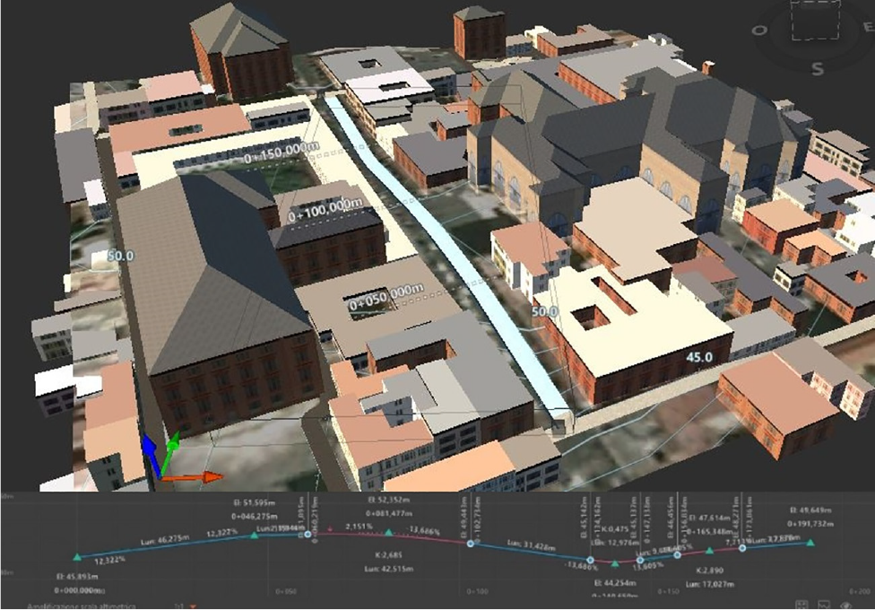
Via Duomo Infraworks model and its vertical profile.
Revit is usually used for vertical construction, so to adapt this BIM-based tool to the case study, preliminary operations needed to be carried out; in particular:
following the logic that for two level curves the slope is constant, Revit floor elements should be produced in such a way as to adapt to the required slopes, creating work plans able to follow the elevation of the ground surface;
families created with Dynamo need to be added in Revit and then assembled, following the horizontal–vertical alignment of the topological surface. As in Revit the floor can have exclusively a horizontal trend, is necessary to identify a level for each small variation in the terrain slope and, clearly, the closer they are to each other, the better the final graphic rendering will be.
Once the initial conditions have been defined, the floor-pavement can be created associating its own reference plane, defining its geometry, creating the shape and then the solid from which it extrudes. The required stratigraphy will be applied to the floor-pavement element and material information. Only in the case of the sidewalk, an offset of 15 cm has been defined, equal to the curb height.
Finally, all pavement families of each road element were joined, including curbs, sidewalk, and pedestrian crossings for the autonomous mobility of people with visual disabilities. The result is shown in Figure 9.
Overview result: (a) top view and (b) 3D view.
Information Management
Using the catalogue on stone pavement in urban areas ( 26 ), a library listing the different stone paving alternatives (an extract is shown in Table 2) was created, also including other materials such as limestone, and other parameters such as average daily traffic (ADT).
Stone Pavement Library Extract
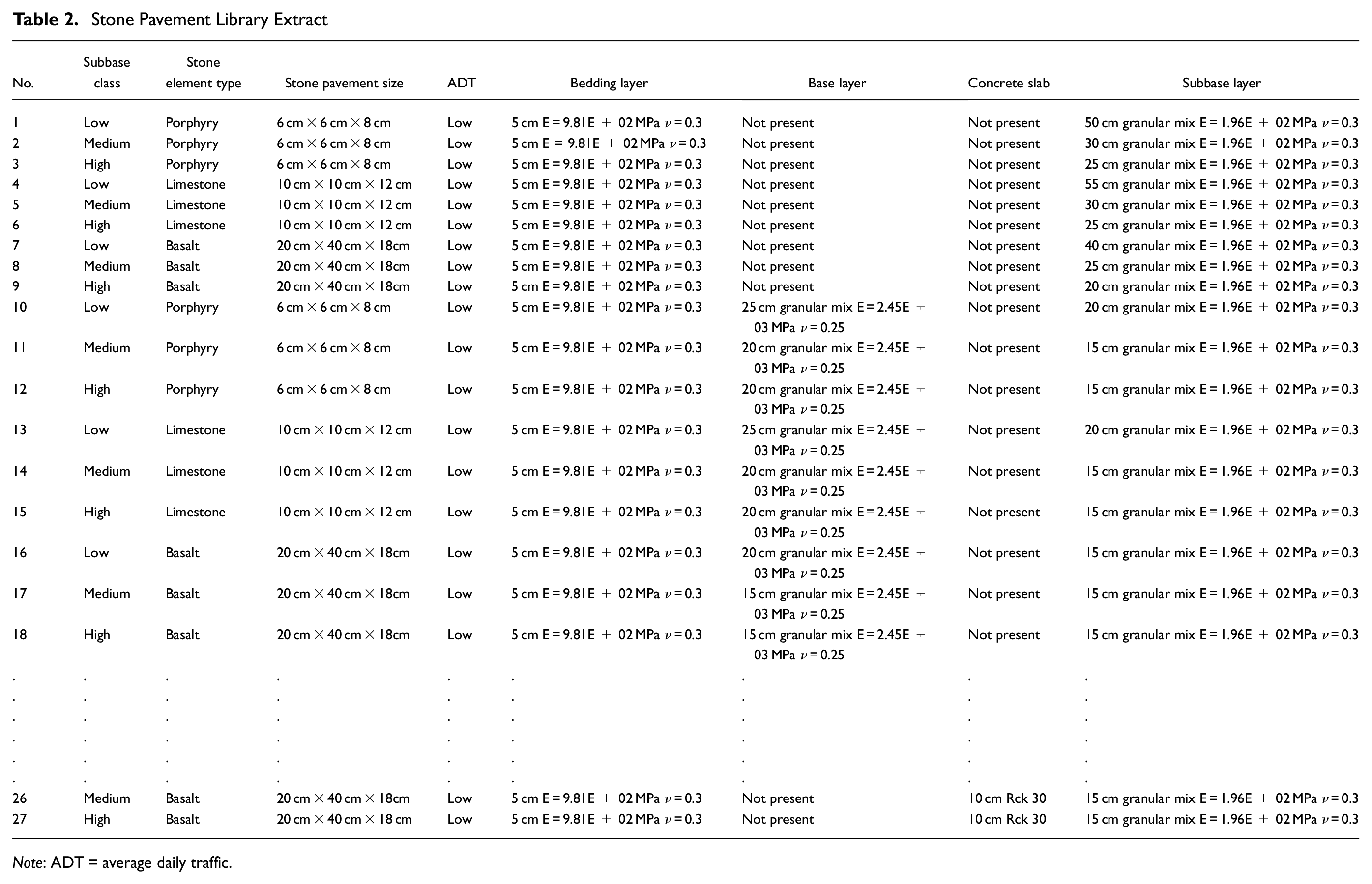
Note: ADT = average daily traffic.
The listed alternatives depend on the possible combinations by varying the stone element type and size, subbase class, bedding and subbase layer properties, presence of base layer and/or concrete slab, and ADT level.
For determining stress–strain state, each layer of the pavement was modeled as an elastic, homogeneous, and isotropic material, characterized by a Young Modulus (E) and a Poisson coefficient (ν), which all together contribute to the bearing capacity of the pavement and can be more or less suitable to different ADT levels.
A multilayer flexible substrate model under a design load equal to 6.5 decanewton per square centimeter was considered for the calculation of stress and strain levels in the pavement, allowing us to calculate in certain points of the pavement (i.e., on the surface of the pavement, on top of the subgrade, and at the interfaces between the layers) horizontal and vertical stresses, strains and, eventually, displacement.
First, Revit was used to create a database structure for the different pavement layers and associate to them the main road parameters, defined as attributes (material type, thickness, safety factors) of the mentioned geometrical entities. Then, based on the information set in Table 2, in Dynamo an ad-hoc algorithm was designed, able to identify the optimal solution based on the above designer constraints.
The final result, as shown in Figure 10, ensures that each pavement element modeled in Revit brings along with itself all the properties, both structural and stress-deformation, converting these objects from pure graphic solids into parametric entities coherently not only with the design objectives but also with the BIM methodology.
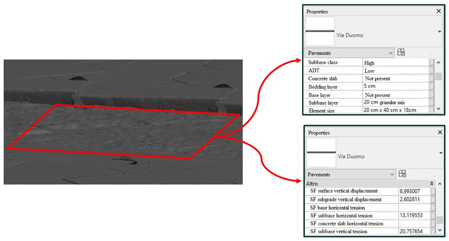
Parametric pavement element overview.
Safety factor (SF) values, defined as the ratio between the observed displacement/tension value and the limit value to ensure the road’s functional conditions, were calculated with an external structural tool and then implemented in the presented model.
The pavement section definition is currently based on few attributes, mainly traffic level and subgrade bearing capacity, so it is more of a BIM use case to show the applicability and visualization potential of such tool.
Conclusions
The purpose of this study is in line with the objective of the Project of National Interest – PRIN 2017 “Stone Pavements. History, Conservation, Valorisation and Design” (20174JW7ZL) financed by the Ministry of Education, University and Research (MIUR) of the Italian Government.
The paper focuses on developing a first BIM-based approach to support the management of historical pavement maintenance data. In this BIM-based approach, the pavement layers are defined as “smart objects,” based on specific relational databases, that may represent a more suitable instrument for handling pavement condition and quality information in a user-friendly software environment. The potential of modern survey technologies may be integrated and optimized in this BIM process, involving in parallel both design of proper pavement solutions and analysis of survey data ( 27 ).
By using a BIM-based approach, a digital parametric model of an existing heritage stone pavement was carried out, where every single element was converted by simple graphic entities into intelligent entities through an original computational design code. In this way, the applied methodology resulted in a dynamic model that updates its information package and modifies the output of the analysis every time the data worksheet is integrated with new collected results ( 28 ).
Future follow-up studies will investigate the possibility of using the proposed tool for road pavement maintenance operations. For this purpose, ongoing survey activities will contribute to collecting additional mechanical information using skid resistance tester, falling weight deflectometer, and dynamic cone penetrometer. These data will be implemented in the proposed tool through scripts with the aim to be an alternative tool that can be used by government bodies responsible for conservation and preservation of the territory, to manage in the best way:
decay monitoring, also structural, through a computerized comparison between data added in the digital model and the same data detected in real time through sensors;
planning of maintenance and restoration interventions, providing information as an alert system identifying what does not work in maintenance operations.
However, some difficulties also arose, such as the lack of available technical documentation (i.e., on pre-existing basoli, as their dating has not included laboratory tests on mechanical properties over the years), combined with high computational processing times of the procedure.
As future developments, it is recommended to carry out high-definition surveys with the use of drone, laser scanner, or both, to obtain a georeferenced points cloud, and thus a more accurate and detailed model, and also to integrate the database with additional attributes by carrying out more in-depth research, such as stone joint modeling and its relative design methods, and the influence of laying patterns on the behavior of historic stone pavements ( 29 – 31 ).
BIM can also contribute toward the dissemination of the infrastructure heritage for a wider audience through virtual reality and augmented reality technologies.
Footnotes
Author Contributions
The authors confirm contribution to the paper as follows: study conception and design: SAB and GD, data collection: CO and NV, analysis and interpretation of results: SAB, CO, NV, GA, FR and GD, draft manuscript preparation: SAB. All authors reviewed the results and approved the final version of the manuscript.
Declaration of Conflicting Interests
The author(s) declared no potential conflicts of interest with respect to the research, authorship, and/or publication of this article.
Funding
The author(s) disclosed receipt of the following financial support for the research, authorship, and/or publication of this article: The research was developed within the Project of National Interest – PRIN 2017 “Stone Pavements. History, Conservation, Valorisation and Design” (20174JW7ZL) financed by the Ministry of Education, University and Research (MIUR) of the Italian Government.