
Abstract
Biochar has been identified as an efficient soil amendment, and it shows promising results in inhibiting desiccation cracks. However, the effects of biochar on soil freeze–thaw cycle behavior on surface cracking have not been considered. This study focuses on the influence of wood biochar dosages on surface cracking under freeze–thaw cycles on clayey soils, and the mechanism was investigated through image analysis and water evaporation. Samples were prepared with different biochar dosages of 0%, 5%, 10%, and 15%, and maintained for 12 h constant temperature freeze (−20°C) and thaw (21°C) cycles. Every 12 h, sample weight, 2D images, and 3D scans were taken. Also, a parallel desiccation experiment was conducted at room temperature for comparison purposes. Results show that with an increased dosage of biochar for the freeze–thaw samples, the crack ratio, fractal dimension, total crack length, and average crack width decrease. Also, the crack propagation rate decreased with the increased amount of biochar. Further, the water evaporation rate decreased with increasing biochar for the freeze–thaw samples; the reasons can be correlated with the reduced thermal conductivity of soil with added biochar, and the reduction in bulk density causing reduced thermal conductivity. Results indicate that the final crack patterns are associated with the initial ice crystal patterns. Samples with low biochar produced larger-sized parallel layered texture ice crystals, and increased biochar content caused homogeneous massive ice crystal texture; these responses can be correlated with changes in soil hydraulic conductivity.
Keywords
Biochar has recently been considered a viable solution for improving soil quality and general soil condition. Biochar is produced by the slow and incomplete combustion of organic materials ( 1 ). Biochar has lower particle density, a higher surface area, a coarser particle size, and a greater water-retention capacity compared with soil minerals ( 2 ). Adding biochar to soil has been considered in various situations, including soil fertility ( 3 , 4 ), remediation of contaminated soils ( 5 ), soil carbon sequestration ( 6 ), and improving soil’s physical and chemical properties ( 7 ). Further, several studies have focused on the effect of biochar on the cracking behavior of silty–clayey soils under desiccation and wetting–drying cycles ( 8 – 12 ). However, among the various biochar applications, little attention has been given to engineering applications, and no research has been undertaken on the impact of the freeze–thaw cycle on surface crack development.
The recent rapid environmental changes, including global warming, have led to significant changes in frozen soils, including permafrost and seasonally frozen ground. The literature confirms that seasonally frozen grounds account for 23% of the total global land area ( 13 , 14 ). Freeze–thaw cycles related to seasonal temperature changes in cold regions greatly influence geotechnical infrastructure and significantly affect pavement foundation performance because of deterioration of pavement quality and rising slope instability ( 15 ). The freeze–thaw process significantly alters the soil structure and affects its physical-mechanical properties ( 16 ). Literature studies on changes in physical properties resulting from freeze–thaw cycles are related to soil permeability, void ratio, porosity ratio, and particle size distribution. Studying the changing mechanical properties is mainly related to strength and deformation changes under freeze–thaw cycles ( 16 ). The freeze–thaw cycle affects the soil strength degradation as a result of macro and microcrack formation and frost heaving ( 14 ). Therefore, it is of significant importance to study the freeze–thaw cycle behavior and find possible soil-improvement methods to mitigate associated problems and support engineering applications.
Biochar has been recognized as a potentially helpful amendment material for improving the physical, mechanical, and hydraulic properties of soil. Biochar enhances soil’s physical quality by increasing porosity, aggregate stability, water retention, water flow, and gas exchange ( 2 ). As the literature explains, biochar generally reduces soil bulk density and tensile strength, improves soil structural quality by soil aggregation, alters the water-transmitting characteristics of the soil, and increases the water-retention capacity ( 1 ). Further investigation of the literature confirms very few studies on the thermal properties of biochar and suggests the possibility of moderating soil temperature and reducing rapid fluctuations in soil temperature ( 1 , 17 ).
Over the last few years, many studies have been conducted on soil biochar amendment to minimize desiccation cracks ( 8 , 9 , 11 , 18, 19). According to Lu et al., biochar lowers desiccation cracks by decreasing tensile stress on the soil surface, increasing repulsive forces between soil particles, occupying the shrinking space between soil particles, and decreasing tensile strength between soil particles ( 11 ). Further, they explain that biochar’s influence is not limited to the final crack pattern but influences the whole process during water evaporation and crack development. Furthermore, Lu et al. investigated the effect of biochar particle size and dose on the desiccation cracking properties of silty clay and discovered that using 10% biochar with fine particle size had the highest performance in preventing soil cracking ( 9 ). Therefore, as the previous studies are limited to biochar’s impact on desiccation cracking and wetting and drying cycles on crack propagation, we explored the freeze–thaw cycle of surface crack formation under different biochar dosages.
Materials and Methods
Experimental Materials
Soil
The soil was collected from a local site in New Jersey for this experiment. The collected soils were oven-dried at 60°C for 48 h and crushed to round 0.25 mm size particles using the grinder. Then soil was prepared using 70% passing the No. 200 sieve and 30% passing the No. 10 sieve and retained on the No. 200 sieve. Table 1 shows the soil properties used for this experiment.
Physical Properties of Soil and Biochar

Biochar
Biochar was purchased from Wakefield Biochar company, and was produced by wood pyrolysis. Then biochar was air-dried at 40°C for 48 h and crushed. Based on the previous research studies, we selected fine-grain biochar (fine: <0.25 mm, coarse: 0.25 mm < size <2 mm) for our experiment ( 9 – 11 ). Therefore the crushed biochar was sieved through a 0.25 mm (No. 60 sieve). The properties of the biochar are also listed in Table 1.
Sample Preparation
Based on the previous research, biochar mass proportions of 0%, 5%, 10%, and 15% (w/w) were selected for this experiment ( 8 , 9 , 11 ). First, the soil was collected into a plastic container, and the measured amount of biochar was added to the container and mixed well. Then 80% (w/w) of water content was added to the soil, mixed homogeneously, and allowed to stand for 12 h under the watertight condition, and then samples were prepared in the Petri dish. Then, the samples were allowed 24 h of moisture equilibrium to reach homogeneous moisture distribution within the soil matrix under moisture-tight conditions. Our main experiment was conducted for the freeze–thaw cycle test, and for comparison purposes, parallel samplings were made for desiccation cracking. Further additional replicate samples were made to investigate the content of biochar for the crack analysis, and for this purpose, two shapes of Petri dishes were selected, circular and square. Therefore, Series A—a circular 84 mm diameter with a thickness of 19 mm Petri dish—and Series B—a square side length of around 90 mm with a thickness of 13 mm Petri dish—were selected for two experimental setups: freeze–thaw, and desiccation. Thus for each biochar dose, four samples were prepared. However, primary experiment analyses were conducted on Series A—circular Petri dish with the freeze–thaw sample. Other samples were used only for the final crack pattern evaluation under the influence of different biochar contents.
All samples were prepared by starting with the total solid mass (soil plus biochar) of 40 g and adding 80% of gravimetric water (w/w) content for the circular Petri dishes and 50 g of a solid mass with 80% water content for the square-shape Petri dishes. However, as we prepared four samples for each biochar dosage, two for freeze–thaw and two for desiccation, we prepared the entire sample at once to prepare four different Petri dishes, and Figure 1a shows the sample preparation mix design.
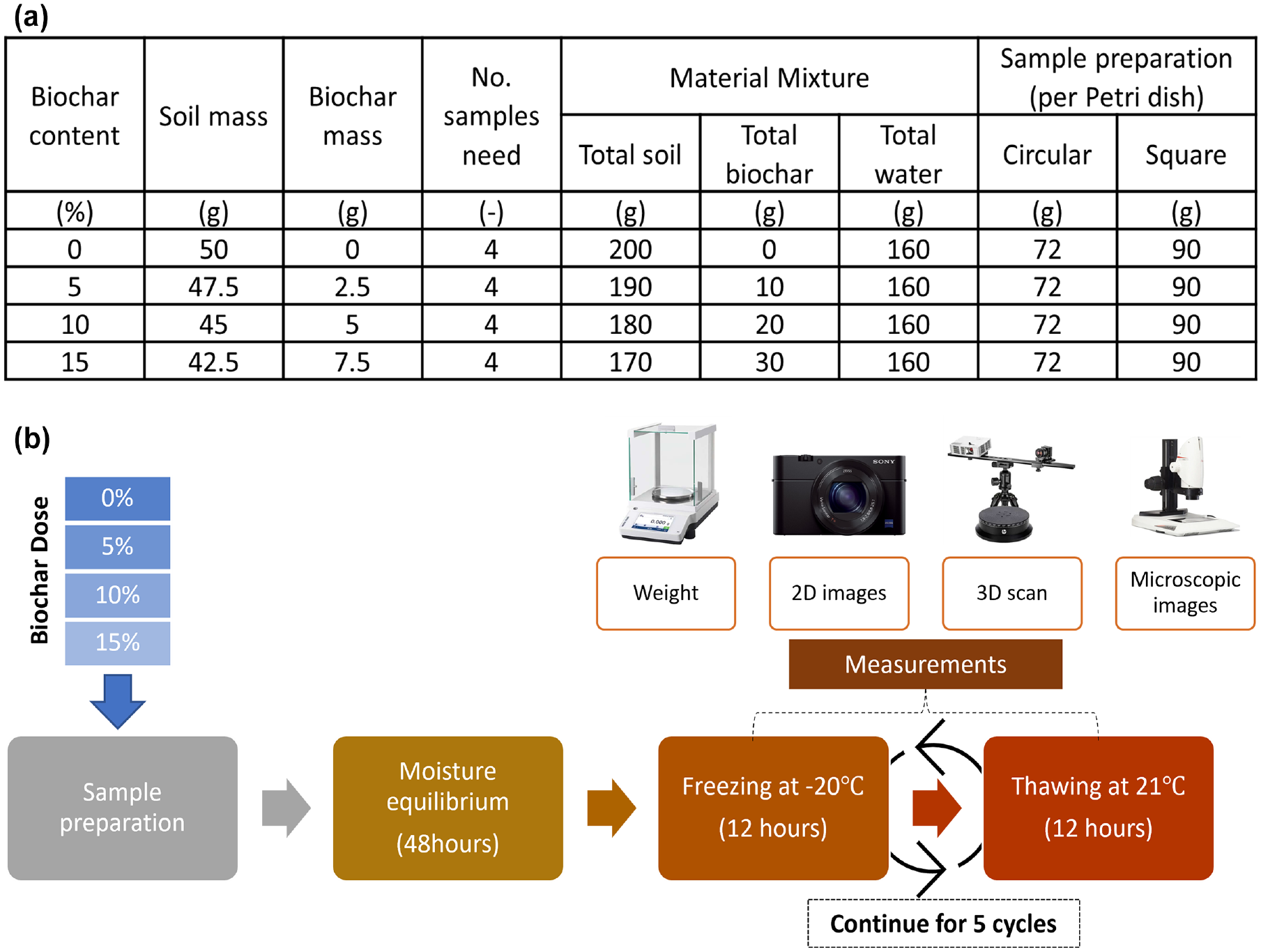
Experimental procedure: (a) sample preparation mix design, and (b) schematic diagram of the freeze–thaw experimental process.
Freeze–Thaw Cycles
As shown in Figure 1b, the prepared samples were maintained for a freeze–thaw experiment sequence, including freezing for 12 h at −20°C, then thawing for the next 12 h at room temperature (21°C) and continuing the same cycle to complete five freeze–thaw cycles. The freeze–thaw experiments were conducted in an environmental chamber (Caron freeze–thaw chamber, model 7900-25-2 208/230VAC), with a constant freezing temperature of −20°C. At the end of each cycle, sample weight, 2D images, and 3D scans were taken. 2D images were taken using a digital camera (Sony Cyber-shot DSC-RX100V), and 3D scans were captured using the HP 3D Structured Light Scanner. Also, after the first cycle of freezing frozen samples, images were taken using a microscope. Figure 1a shows the sample preparation mix design, and the schematic diagram of the freeze–thaw experimental process is shown in Figure 1b.
Desiccation Samples
In this experiment, only one continued desiccation was performed, and no wetting–drying cycles were conducted. As many researchers have studied biochar-amended soil desiccation cracking behavior, this test was conducted only to compare with the freeze–thaw behavior. All the prepared samples were allowed to desiccation at room temperature at 21°C.
Image Processing and Quantitative Analysis
2D Image Processing
Tang et al. created the Crack Image Analysis System (CIAS), which was used to analyze 2D pictures ( 20 ). Image segmentation, fracture identification, and measurement are required to quantify crack pictures using CIAS. The camera captured a picture of 5,472 by 3,648 pixels, which was subsequently cropped and reduced to 1,000 by 1,000 pixels for the 84 mm diameter Petri dish. As a result, the CIAS processing utilized a resolution of about 12 pixels/mm. Figure 2 illustrates the essential phases in the crack image-processing operation, including color picture, grayscale image, binary image (using cluster analysis method), and skeleton image. Finally, the various crack metrics, such as crack area, crack length, average crack width, and fractal dimension, were computed. The fractal dimension represents the heterogeneity, complexity, and irregularity of the sample, and the higher the fractal dimension shows, the higher heterogeneity. Liu et al. explain the crack matrixes mentioned above ( 21 ).

Digital image-processing procedure: (a) original color image, (b) gray image, (c) binary image, (d) crack skeleton.
3D Scan Image Processing
The 3D photos were captured using a 3D scanner (HP 3D scanner). Four pictures with a 90-degree rotating angle were used to scan each sample. At the end of the scan, all four scans were verified for alignment correctness, and if necessary, alignments were rectified before fusing all of the scan pictures with the greatest resolution (vertex spacing 0.0559 mm). The fusion results were then stored as the .obj file type. The post-processing was then carried out using the MATLAB algorithm created by Zhou et al. ( 22 ). The procedure involves exporting the surface coordinates to MATLAB, moving the coordinates into an orthogonal plane, eliminating noise, mapping the surface, drawing the 3D surface and cross-section fluctuating curves, and mapping the surface again as shown in Figure 3.

MATLAB approach for 3D scan image analysis.
Results
Evaporation Characteristics of Biochar-Amended Soils
Figure 4 represents the variations in gravimetric water content of biochar-amended soils over time and with various biochar doses for two types of Petri dishes, circular and square. Weight measurements were recorded at the end of each 12-h freezing and thawing cycle. Figure 4, a and d , shows the temporal weights of samples. Figure 4, b and e , shows the temporal water content by assuming the dry weight of the sample as the stable mass at hour 144, and Figure 4, c and f , shows the water evaporation rate as calculated by considering the consecutive 12 h moisture loss. The amount of water lost during the freezing process was less than that lost during the thawing process.
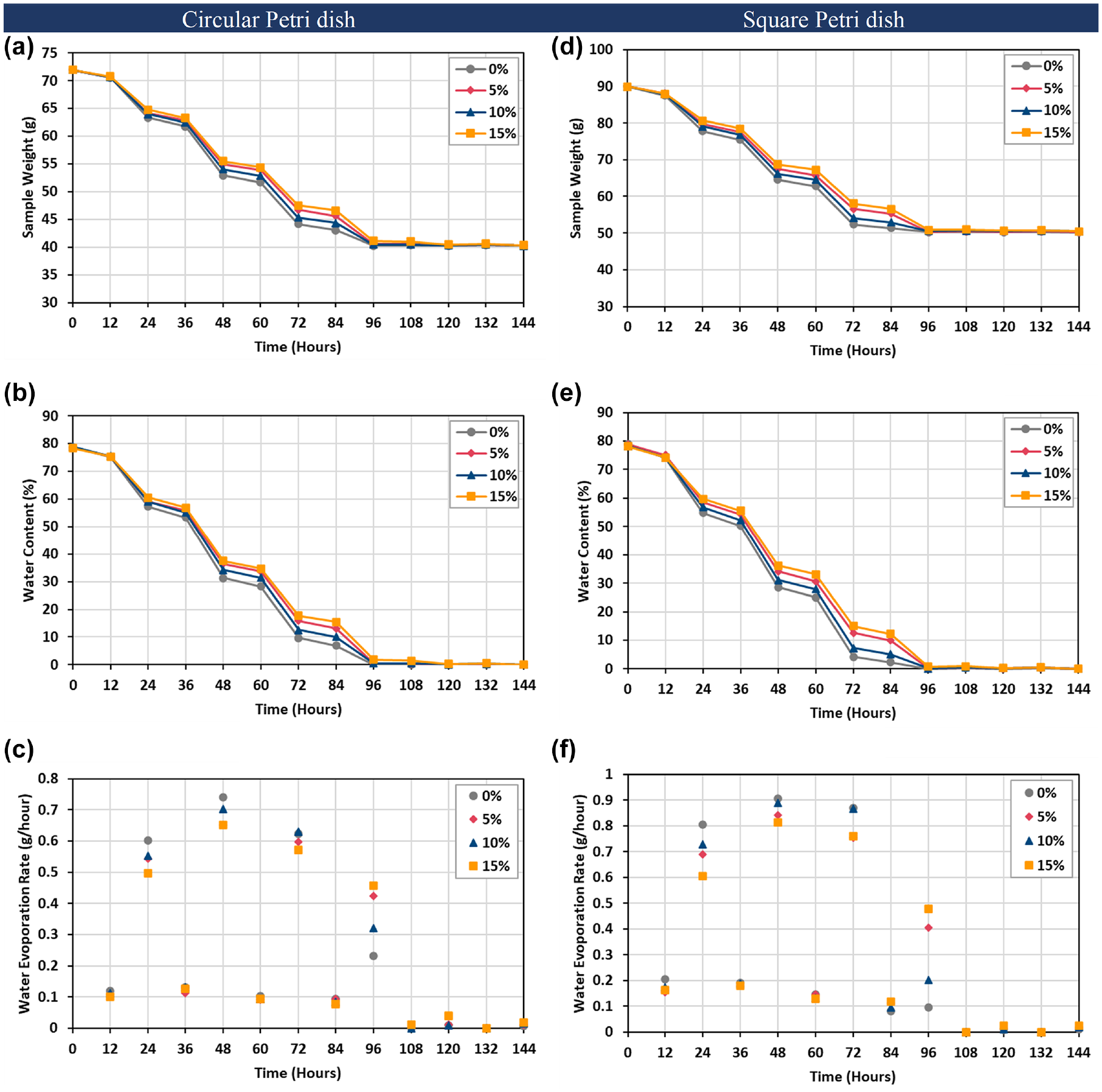
Evaporation process of soil with different biochar contents for freeze–thaw samples with time. For circular Petri dish shape: (a) sample weight, (b) water content, (c) water evaporation rate. For square Petri dish shape: (d) sample weight, (e) water content, (f) water evaporation rate.
Results show that the pattern of water evaporation was relatively similar among different Petri dish shapes, confirming the pattern of water evaporation repeatability among different biochar contents. Furthermore, the water content of all samples started at 80% and, after 96 h, reached the residual state, as shown in Figure 4, b and e . Figure 4, c and f , shows the water evaporation rate with time; the results show that during the freezing process, all the biochar samples had a similar rate of water evaporation, and over time as the water content decreased, the water evaporation rate also decreased. In the first 48 h during the thawing process, the highest water evaporation rate was recorded with the 0% biochar sample, and the lowest rate was recorded with the 15% biochar content. After 96 h, as the 0% biochar sample water content was smaller, the evaporation rate decreased compared with the other samples, and by the next 12 h, it reached a stable weight. Compared with the 5% biochar content, the 10% biochar sample showed a faster evaporation rate during the whole evaporation period. All the samples reached their stable weight after 108 h. In general, added biochar content generally decreased the water evaporation rate in freeze–thaw samples.
Characteristics of Crack Development During Freeze–Thaw Cycles
Visual Observation of Soil Cracking
Figure 5 shows the crack patterns captured at the end of each freeze and thaw cycle (every 12 h) for samples containing varying amounts of biochar. Figure 5 indicates a substantial variation in ice crystal morphologies and crystal density at different biochar dosages during the cycle 1 freezing phase. The sample without biochar had the most and largest ice crystals, but the amount and size of crystals dropped as the biochar level increased. Cycle 1, the thawing phase, shows that some initial cracks open as the ice crystal thaws and water evaporates, and most of the initial cracks are seen with the sample with no biochar content. Very few cracks were opened in cycle 1 after thawing for the higher biochar content. The sample without biochar closes some of the first fractures when the sample volume expands because of the freezing of soil water in the cycle 2 freezing stage. However, there was some initial fracture width growth during the freezing process for the other samples with high biochar doses, and the smaller ice crystals formed in some samples still had a high water content. All of the samples demonstrated crack growth throughout the cycle 2 thawing procedure. The initiation and propagation of cracks in all samples were evident in relation to localized ice crystallization and thawing. For the subsequent freeze–thaw cycles, crack propagation continued for all the samples until the final crack morphology was met. First, the sample with no biochar reached its stable crack pattern by the end of cycle 3, the thawing process. The rest of the samples reached their final crack morphology by the end of cycle 4, the thawing process.
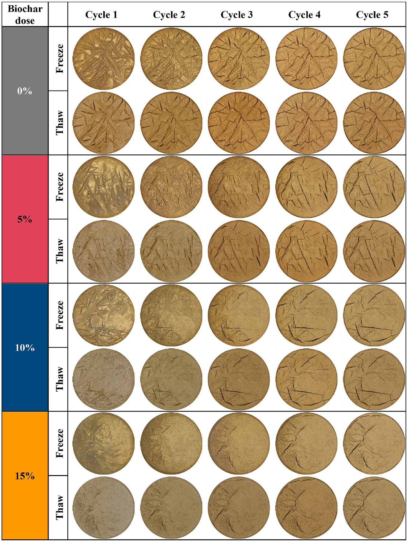
Images of the soil specimen for different biochar doses at the end of each freeze–thaw cycle.
Most of the freeze–thaw damage was seen in the sample with no biochar content, and the quantity of cracking decreased with the increased amount of biochar. Further, the crack propagation rate was quicker with lower biochar content and decreased with increased biochar content. As a result, an excess of biochar lowers the number of cracks while also increasing the time required to generate the final crack pattern.
Quantitative Analysis of 2D Images for Soil Cracking
Figure 6 shows the quantification of different crack parameters for different biochar content. Figure 6a shows the crack ratio with time for four biochar dosages. The crack ratio is the ratio of the surface crack area to the total surface area of the sample. It is clear that all the time, the crack ratio is higher for the sample without biochar content, and the crack ratio decreases as biochar dosage increases. Furthermore, it shows that the crack propagation rate is rapid for the sample without biochar, and the rate decreases with an increasing amount of biochar. The fractal dimension also follows the same trend as the crack ratio, and it shows that the sample with no biochar treatment shows the highest fractal dimension or the most changed surface structure. Crack length also follows the same trend, confirming the positive influence of the biochar on the reduction of crack lengths. However, crack width over time with different biochar contents had a different relationship at some stages, as the number of cracks changed during the crack propagation. But after the complete formation of cracking, the results indicate the same conclusion as the crack width reduction with an increased amount of biochar content.
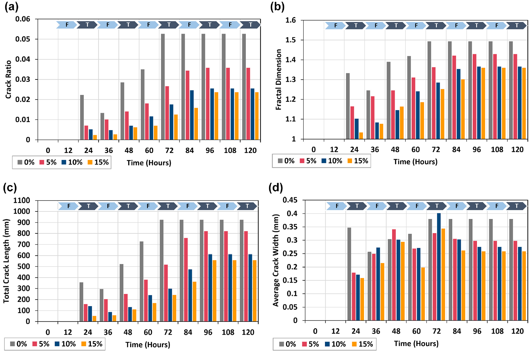
Crack quantification with time of 2D images on the influence of freeze–thaw cycles on varying biochar content: (a) crack ratio, (b) fractal dimension, (c) total crack length, and (d) average crack width.
Quantitative Analysis of 3D Scan Images for Soil Cracking
Figure 7 shows the quantitative values obtained from the 3D image processing. The image-processing parameters of sample volume, fractal dimension, and surface area are shown in the results. Findings from the first 24 h are not presented, as the light reflection from the wet samples reduced and degraded scan resolution, resulting in data point loss. Figure 7a shows the sample volume change with time, and the volume of all samples decreases with time. Change in sample volume over time increased from 0% to 10% biochar content, with the volume change from 36 h to 120 h showing 6.4%, 16.4%, and 23.3% reduction for 0%, 5%, and 10%, respectively. However, the sample with 15% biochar showed a volume reduction lower than 5%, and for 10% biochar content the volume change was 14.2%.

Crack quantification with time of 3D scan images on the influence of freeze–thaw cycles on varying biochar content: (a) volume, (b) average sample thickness, (c) fractal dimension, and (d) surface area.
In addition, the average thickness of the samples was estimated over time using the MATLAB tool for creating cross-section fluctuating curves, as shown in Figure 7b. The average thickness over time remained consistent after 48 h, and the average sample thickness for 0%, 5%, 10%, and 15% biochar content was 65.8 mm, 62.7 mm, 62.1 mm, and 66.7 mm, respectively. The sample volume and thickness shared the same correlation with biochar content, and these results are shown in Figure 8 from the reconstruction of the 3D surface images. Figure 8 shows that the 0% and 15% sample thicknesses are relatively high compared with the other two samples. The estimated fractal dimension demonstrates the complexity of the sample fractures. In 2D image analysis, the fractal dimension trend was closely followed by the surface crack area. It was also valid for the 3D image analysis, showing that the fractal dimension is closely followed by the surface crack area of the 3D images, as shown in Figure 7d. The fractal dimension and the sample volume were not that related, as shown in Figure 7. Figures 7 and 8 show that fractal dimension and surface crack area decrease with increased soil biochar content.
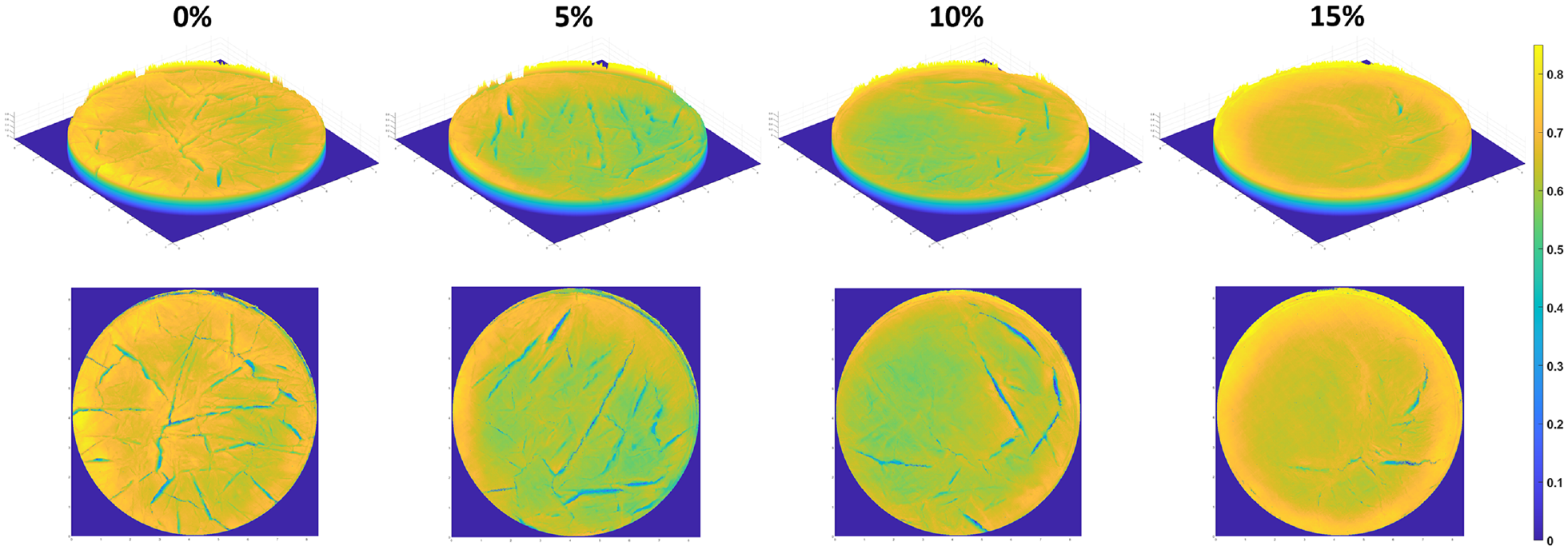
Reconstruction of the 3D surface of the soil samples with different biochar content at the end of cycle 5 (120 h).
Comparison Between the Freeze–Thaw and Desiccation Crack Patterns
Visual Observation of Soil Cracking
We produced two types of samples to examine crack patterns and quantification: Series A in a circular Petri dish and Series B in a square Petri dish. The two types of samples were not prepared to study the impact of Petri dish shapes, and therefore samples were not controlled between maintaining constant volume, mass, or sample thickness between the two Petri dish shapes. Instead, the two series were intended as parallel experiments to investigate the influence of biochar content on freeze–thaw cycles and desiccation. Circular Petri dish samples were prepared with an initial solid weight of 40 g, and square Petri dish samples were made with 50 g of solid weight.
Figure 9 shows the crack patterns captured after samples reached a stable weight for four different biochar contents. It shows circular and square Petri dishes with freeze–thaw and desiccation crack patterns. When comparing the freeze–thaw effect and desiccation, it is apparent that they pose very distinct cracking patterns. Freeze–thaw samples show very discrete short and thinner cracks, whereas the desiccation sample shows a connected crack network with long and thicker cracks. This observation is accurate for both Series A and B.
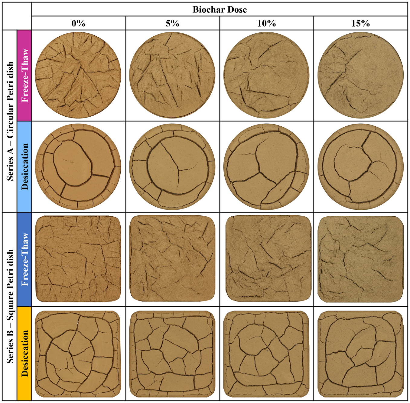
The crack morphology of different biochar content captured after the mass stabilization for freeze–thaw and desiccation sample for two different Petri dishes shapes.
When we look at the Series A freeze–thaw samples, we can see evident changes in crack configuration with the increase in biochar content, and crack reduction with increased biochar content. However, when looking at the desiccation samples, the difference is not that evident by visual observation, yet it was clear that there was crack reduction between 0% and 15%.
The Series B freeze–thaw sample did not show as clear a trend as the Series A, yet it is evident that from 0% to 15%, there was a general crack reduction. We can tell through visual observations and manual inspection of the desiccation samples that the trend of crack reduction with higher biochar concentration is obvious, although the differences are not significant. As a result, it is safer to assume that biochar has a more significant influence on freeze–thaw cycles than desiccation.
Quantitative Analysis of 2D Images for Soil Cracking
The unaided visual inspections are not sufficient for crack quantification. Therefore the 2D image-processing method was used to quantify the crack pattern shown in Figure 9. Therefore, as illustrated in Figures 10 and 11, image analysis results calculated the crack ratio, fractal dimension, total crack length, and crack width for different biochar content for the Series A and Series B images.

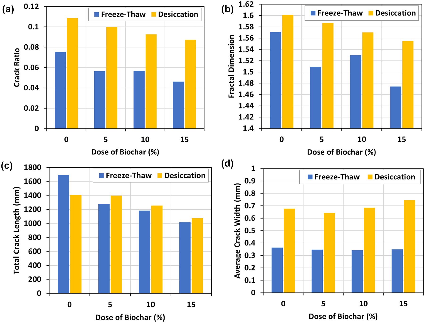
Quantification results of cracks of samples with different biochar dosages for freeze–thaw and desiccation samples for Series A: circular-shaped Petri dishes: (a) crack ratio, (b) fractal dimension, (c) total crack length, and (d) average crack width.
Quantification results of cracks of samples with different biochar dosages for freeze–thaw and desiccation samples for Series B: square-shaped Petri dishes: (a) crack ratio, (b) fractal dimension, (c) total crack length, and (d) average crack width.
Figure 10 shows the fracture quantification data for freeze–thaw and desiccation for Series A: circular Petri dish. It shows that the crack ratio is much higher for the desiccation sample than for the freeze–thaw samples, and the difference was 0.76, 1.38, 2.15, and 2.12 times for 0%, 5%, 10%, and 15%, respectively. However, when separately considering the freeze–thaw and desiccation samples’ crack ratio with respect to the biochar content, in both cases, the crack ratio decreases with an increase in biochar content. Compared with desiccation samples, freeze–thaw samples show a higher rate of crack ratio reduction with increased biochar content. The fractal dimension follows the same trend as the crack ratio, with the desiccation sample having a larger fractal dimension than the freeze–thaw samples. However, differences among the freeze–thaw and desiccation on fractal dimension were not that different from the crack ratio. Desiccation samples had fractal dimensions that were 0.048, 0.084, 0.130, and 0.119 times larger than the freeze–thaw sample for the 0%, 5%, 10%, and 15% biochar content, respectively. However, the total crack length shows different results compared with crack ratio and fractal dimension. The 0% and 5% biochar content show slightly higher total crack length for the freeze–thaw samples compared with desiccation samples, but for the 10% and 15%, the total crack length is higher in the desiccation samples. This behavior can also be seen visually in Figure 9, where the 0% and 5% biochar with freeze–thaw samples show increased surface crack patterns and possibly higher than the desiccation samples, as quantitative analysis demonstrates in Figure 10c. However, the total crack length decreases with biochar increase for both freeze–thaw and desiccation. Visual observations in Figure 9 indicate that the average crack width in freeze–thaw samples is smaller than in desiccation samples and quantitative findings support this, as shown in Figure 10d. Freeze–thaw samples show that the crack width is slightly reduced with increased biochar content but not significantly. The same for the desiccation samples, biochar shows very little influence on the crack width; mostly, they share a similar average crack width of around 0.9 mm.
Figure 11 shows the quantification of crack results on the Series B square Petri dish samples for freeze–thaw and desiccation. The same as the Series A data, Series B also shared mostly the same trend for the crack ratio, fractal dimension, total crack area, and average crack width. As a general trend, crack ratio, fractal dimension, and average crack width were always higher in the desiccation compared with freeze–thaw. Also, the crack ratio and total crack length decrease with increased biochar content for both freeze–thaw and desiccation. However, the fractal dimension had slight changes in the 10% freeze–thaw sample, which was slightly higher than the 5% samples. This factor can be noted in Figure 9 as well, where sample complexity was higher in the 10% sample. Similar to Series A, 0% biochar samples had a higher total crack length for the freeze–thaw sample. However, the rest of the biochar dose desiccation samples had higher total crack lengths than the freeze–thaw samples. The same as Series A, the average crack width did not show that much influence resulting from the biochar content for both the freeze–thaw and desiccation. They shared similar average values among different biochar contents, and the average crack width was around 0.35 mm and 0.69 mm for freeze–thaw and desiccation, respectively.
Discussion
Water Evaporation
Water evaporation is one of the primary variables influencing the initiation and propagation of cracks in clayey soil. The results indicate that the water evaporation rate decreases for the samples with high biochar content during the thawing process, as shown in Figure 4, c and e . All the samples had a similar water evaporation rate during the freezing period, and were much smaller than during the thawing. Furthermore, desiccation results also follow a similar trend as the water evaporation rate decreases with increased biochar content (Figure 12). However, 5% biochar content for desiccation samples had a relatively higher or equal evaporation rate compared with bare soil (0% biochar), which was true for both circular and square Petri dish data. Thus, for desiccation, with a low content of biochar the evaporation rate increases, and with increased biochar content the evaporation rate decreases. For freeze–thaw samples, the highest evaporation was recorded with the 0% biochar samples, and compared with the 5% sample, 10% biochar content showed faster evaporation rates. However, in both desiccation and freeze–thaw conditions, 15% biochar content showed slower evaporation rates than samples with lower biochar contents. These results can be attributed to the biochar having a high water-retention capacity compared with soil minerals ( 19 , 23 ). In general, the water-absorption capacity of biochar is six times its weight ( 24 ). However, grinding the biochar to produce finer particles can influence the water-holding capacity as it destroys the pore structure, reducing the water-absorption capacity and hydraulic conductivity ( 25 ). Therefore, when the biochar content increases, the amount of water attached to these samples also increases. Also, water evaporation rates are lower during the first 12 h in freeze–thaw samples compared with desiccation samples. Also, for freeze–thaw samples, the water evaporation rate decreases with increased biochar content, as shown in the 12 h data, indicating that the thermal properties of biochar-amended soil play a vital role in freeze–thaw behavior and water evaporation from the soil surface.
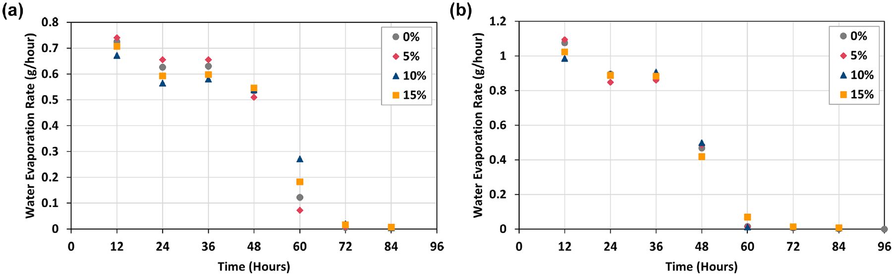
Water evaporation rate for the desiccation samples: (a) circular Petri dish and (b) square Petri dish.
The literature confirms that the thermal conductivity of soil decreases with added biochar, and the main reason for the impact of thermal conductivity resulting from the amendment of biochar is attributed to a change in soil bulk density ( 17 ). Therefore, the thermal conductivity of soil decreases with a decrease in soil bulk density. The bulk density of soil decreased with increased biochar content, and calculated bulk densities at the soil slurry at the sample preparation were 5%, 10%, 15%, 1.52 g/cm3, 1.46 g/cm3, and 1.4 g/cm3. Also, the calculated bulk density based on 3D scan analysis data of the freeze–thaw samples after reaching stable weight for added biochar 0%, 5%, 10%, and 15% was 1.08 g/cm3, 1.06 g/cm3, 1.04 g/cm3, and 0.95 g/cm3, respectively. Further, an additional test was conducted to measure the thermal conductivity of biochar-amended soil. Thermal conductivity was measured using the TLS-100 portable thermal conductivity/thermal resistivity meter. Thus three replicates of 0%, 5%, 10%, and 15% biochar content soil samples with 70% water content were prepared with a constant mass of 70 g in the 50 ml plastic centrifuge tubes. Once the samples were prepared, the initial thermal conductivity was measured at room temperature, and samples were placed at −20°C for 24 h under moisture-tight conditions. After completion of the freezing process, samples were tested at an interval of 3 h, 6 h, and 12 h during the thawing phase. Water loss was not allowed for the thermal conductivity test during the freezing or thawing process. The results are plotted in Figure 13a, confirming that thermal conductivity decreases with increased biochar content, especially with respect to the wet sample data before freezing and after 12 h of thawing samples, as shown in Figure 13b. The fluctuation in results at 3 h and 6 h of thawing can be considered as caused by the impact of ice crystals on the thermal conductivity meter and should not be considered representative of the thermal conductivity of the samples. Thus allowing for thawing of frozen samples at room temperature, thermal conductivity controls the rate of temperature increase and, after reaching equilibrium temperature, might maintain the lower temperature inside the soil as reported in the literature ( 17 ), causing the reduced rate of water evaporation with respect to higher biochar content for the freeze–thaw samples.
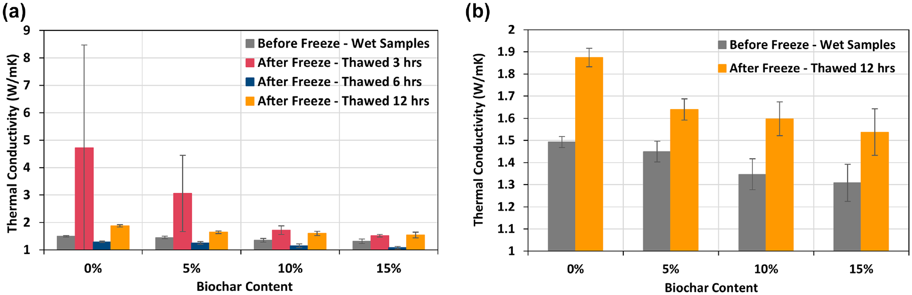
Thermal conductivity under different biochar content: (a) all data (b) samples were under room temperature.
Overall results suggest that the water evaporation rate of the soil is controlled by the combined effect of several positive and negative correlated factors with added biochar. Thus, with added biochar, increased sample porosity positively correlates to water evaporation, and as biochar content increases, reduced thermal conductivity and increased water retention cause a negative correlation to water evaporation.
Frost Heave and Ice Crystal Formation
The frost texture is formed by the reconstruction of the intact soil system with a change in its thermophysical properties ( 26 ). Figure 14 shows microscopic images of the frozen soil surface at the cycle 1 frozen stage for different biochar content. It shows that the size of the ice crystals decreases with an increasing amount of biochar content. Figure 5 shows that final crack patterns are defined from the initial ice crystal pattern in the frozen soil sample. Therefore, ice crystals control the final crack patterns and reduce the crack widths and crack lengths as well as the fractal dimension and crack ratio, as shown in Figure 6 for high biochar content.

Microscopic image for frozen samples at cycle 1.
In general, ice crystals first form and then continue to grow by pulling the water from the surrounding soil ( 26 ). There are three main types of frozen soil structures: (I) a homogeneous or “massive” texture that happens with rapid freezing, (II) a layered texture made of parallel, lens-shaped ice layers that results from a slower rate of freezing, and (III) a lattice texture with irregularly oriented ice crystals ( 26 ). Therefore, based on experimental results shown in Figure 5, we can assume that with the lower content of biochar, there are more layer-texture ice crystal forms, and with increased biochar, more homogeneous ice crystals are formed. This can be attributed to the increased biochar content resulting in reduced bulk density and increased porosity with increased saturated hydraulic conductivity. According to the literature, biochar-amended soil, on average, reduced hydraulic conductivity (K) in the sand and organic soil while increasing K in clay-rich soil ( 27 ). That allows for faster water movements and the faster formation of ice crystals forming homogenous textures. In contrast, the bare soil sample has higher bulk density and lower permeability than samples with biochar. At the same time, the bare soil sample contains more clay particles than the sample contains biochar. Also, the clay particles contain a non-freezable water layer and high unfrozen water content. With these factors, we can assume that freezing of bare soil takes more time and causes a slow rate of crystal formation compared with the soil treated with biochar. That might be the reason for Figure 5 showing layered ice crystals in the 0% biochar sample.
Biochar-Amended Soil Surface Characteristics
Figure 15 shows the microscopic images of the freeze–thaw samples with different biochar contents after reaching stable weight. When we closely examine the surface structure of those microscopic pictures, we can see the distribution of biochar particles, micro-cracks, and connections between particles. For example, Figure 15 demonstrates that 0% biochar samples had a smoother particle surface with more apparent micro-cracks, whereas soil samples appear to have a looser soil structure. At the same time, the samples with increased amount of biochar show a more intact soil surface with soil particles interlocked with the added biochar, and show the reduction in micro-cracks with increased biochar content. This is quite obvious in the 15% biochar content, as seen in Figure 15. Therefore, as the literature confirms, biochar has the potential to improve soil aggregation and increase the proportion of water-stable aggregates ( 1 ).
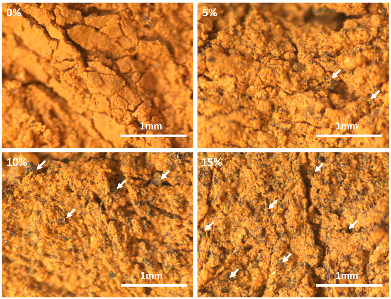
Microscopic images on the soil surface amended with different biochar content after completion of water evaporation (white color arrows show biochar particles).
Different literature has concluded that adding biochar enhances the soil’s water-retention capacity ( 28 ). Increased water retention or higher water content in soil with biochar amendment resulted in reduced suction or lower tensile stress as a result of less water loss in drying or evaporation compared with soil without biochar amendment, and caused fewer cracks ( 11 , 28 ). The smaller-sized intra-pores in biochar are responsible for enhanced water retention in biochar-amended soil because they hold water firmly and do not let water leave readily, reducing water evaporation and resisting cracks ( 11 , 28 ). Therefore, especially for the desiccation samples shown in Figure 9, reduced crack ratio and fractal dimension with added biochar can be attributed to increased water retention.
Conclusions
Clayey soil surface crack remediation with biochar has been studied previously for desiccation and wetting–drying cycles. However, no studies have been conducted to evaluate biochar’s impact on the freeze–thaw cycle behavior of clayey soil. The analysis of experimental results yielded the following major findings.
(1) For the desiccation samples with low biochar content, the evaporation rate decreases, and with increased biochar content, the evaporation rate increases. For freeze–thaw samples, the water evaporation rate decreased with increased biochar.
(2) With added biochar, the water evaporation rate is controlled by several factors, such as porosity, thermal conductivity, and water-retention capacity. Added biochar causes an increase in porosity, a decrease in thermal conductivity, and an increase in water retention.
(3) Reduction in thermal conductivity is correlated with the reduced bulk density of biochar-amended soil.
(4) The initial ice crystal patterns highly influence the final crack patterns of the freeze–thaw samples. Sample with low biochar produced larger-sized parallel layered texture ice crystals, and increased biochar content caused homogeneous massive ice crystal texture.
(5) The quantitative analysis of freeze–thaw sample crack patterns shows that with an increased dosage of biochar, the crack ratio, fractal dimension, total crack length, and average crack width decrease. Also, the crack propagation rate decreased with the increased amount of biochar.
(6) Compared with desiccation cracking, freeze–thaw samples show a smaller crack ratio, fractal dimension, and average crack width. However, for the lower biochar contents, 0% and 5% show that total crack lengths are higher for the freeze–thaw samples.
(7) Based on the results, the added biochar can improve the soil cracking behavior for both the desiccation and freeze–thaw cycles. Further, biochar can moderate soil temperature, which provides a threshold for withstanding a period of drying and still maintains the function of a hydraulic barrier for the reduction in cracking in the soil samples. Thus this study provides new insights into biochar-amended soil to improve the freeze–thaw behavior of clay soils and may contribute to future study considerations of climate-resilient infrastructure.
Footnotes
Author Contributions
The authors confirm contribution to the paper as follows: study conception and design: Cheng Zhu, Shaini Aluthgun Hewage; data collection: Shaini Aluthgun Hewage, Kaniz Roksana; analysis and interpretation of results: Shaini Aluthgun Hewage, Kaniz Roksana, Chao Sheng Tang, Zhuang Zhuo; draft manuscript preparation: Shaini Aluthgun Hewage, Cheng Zhu. All authors reviewed the results and approved the final version of the manuscript.
Declaration of Conflicting Interests
The author(s) declared no potential conflicts of interest with respect to the research, authorship, and/or publication of this article.
Funding
The author(s) disclosed receipt of the following financial support for the research, authorship, and/or publication of this article: This study is funded by Camden Health Research Initiative.