
Abstract
Background
The supporting structure of high-temperature gas-cooled reactors (HTGR) comprises over 3000 carbon/graphite components, necessitating computed tomography (CT) non-destructive testing before operational deployment as per reactor technical specifications. However, CT images are frequently marred by severe ring artifacts due to the response non-uniformity and non-linearity of detector units, which diminishes the ability to detect defects effectively.
Methods
To address this issue, we propose a physics-based ring artifacts reduction method for CT that employs pixel response correction. This method physically accounts for the cause of ring artifacts and leverages the prior knowledge of the detected object to enhance the accuracy of the detection process.
Results
Our proposed method achieved a notable reduction in ring artifacts, as evidenced by a 37.7% decrease in ring total variation (RTV) values compared to the originals, significantly enhancing image quality. It also surpassed traditional and machine learning methods in artifact reduction while maintaining image details. The lower RTV scores confirm our method's superior effectiveness in minimizing ring artifacts.
Conclusion
We believe that our research contributes to the enhancement of defect inspection performance in detection systems, which is crucial for ensuring the safety of reactors. The proposed method's effectiveness in mitigating ring artifacts while maintaining image quality highlights its potential impact on the reliability of non-destructive testing in the context of HTGR components.
Introduction
The Chinese design of the high-temperature gas-cooled reactor (HTGR), 1 called high-temperature gas-cooled reactor-pebble bed module (HTR-PM), has entered the commercialization stage 2 and is of paramount importance to optimize the energy structure and achieve carbon neutrality. With excellent neutron moderation ability and high-temperature mechanical properties, graphite and carbon are processed into structural components to form the core of HTR-PM and provide channels for inserting control rods and conveying coolant.3,4 Because of radiation damage and radiolytic oxidation, the original defects arising from production and transportation inside these nuclear graphite components might gradually expand to cracks during service, eventually threatening the safety of the reactors. 5 Without a doubt, the structural integrity of these components is one of the most important factors relevant to the lifetime of reactors.
To identify the internal defects and screen out unqualified components, a helical CT detection system is designed for volume detection before these components are stacked. 6 Suffering prolonged irradiation from high-intensity and high-energy rays, the detectors will be subjected to cumulative radiation damage, which will affect the linearity and consistency of the detector response, leading to ring artifacts in the reconstructed images.7,8 Ring-artifact will interfere with the recognition and quantitative analysis of defects in graphite components volume detection that it must be calibrated to ensure the reliability and longevity of the detection system.
Traditional ring artifact reduction methods can be classified into post-processing methods based on reconstructed images and pre-processing methods based on projection data.9–14 Benefiting so much from the rapid development in computing and machine-learning technology, iterative algorithms15–17 and deep learning algorithms have also been applied more often in CT image processing.
Although these existing methods can somewhat suppress the ring artifacts, they are not competent for millimeter-level defect recognition tasks for large-sized graphite/carbon components. The filtering process in traditional methods may lead to loss of detail and blurring in the original information in CT images. As for methods based on supervised deep-learning algorithms, they may be limited due to the inability to obtain ideal images. To date, no ring artifact correction method can remove artifacts in images without losing critical information in CT detection for large-sized nuclear graphite/carbon components.
This study aims to take advantage of the characteristics of single components and uniform density of carbon components and propose a ring artifact elimination method for CT images based on detector response correction of the physical causes of ring artifacts. Experimental results show that the correction method proposed in this paper can be applied to engineering practice, and this method can effectively reduce ring artifacts while retaining image details and texture.
Method
Ring artifacts
In the process of rays penetrating an object, the intensity of the rays will attenuate because of their interaction with the matter, and the degree of attenuation depends on the substance's absorptivity, which is related to the density and material of the substance. During CT detection, the detector units capture signal
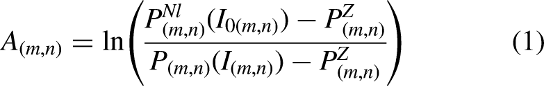
Using computer technology to analyze the data collected at different scanning angles, it is possible to reconstruct CT images that show the inner structure and density of the object without destruction. Under the ideal situation, the response function of the ray intensity of each detector unit is consistent and linear. Ignoring the influence of the noise signal, Eq.(1) can be changed to Eq.(2), and at this point, the response signal of the detector unit can describe the attenuation of the ray.

As shown in Figure 1, we extract the radiation intensity response curves of the two detector units from the actual CT scan data after data cleaning. The vertical axis data corresponds to the detector units’ responses, whereas the horizontal axis data denotes the radiation source intensity incident on the detector units. This intensity is derived from the known activity of the radiation source, along with the graphite component's shape and density, employing the Beer-Lambert law for calculations. They appear inconsistent, and neither follow the standard linear response law. In other words, the value of the ray attenuation coefficient indicated by the data collected by the detector does not exactly match the true value.
Radiation intensity response curves.
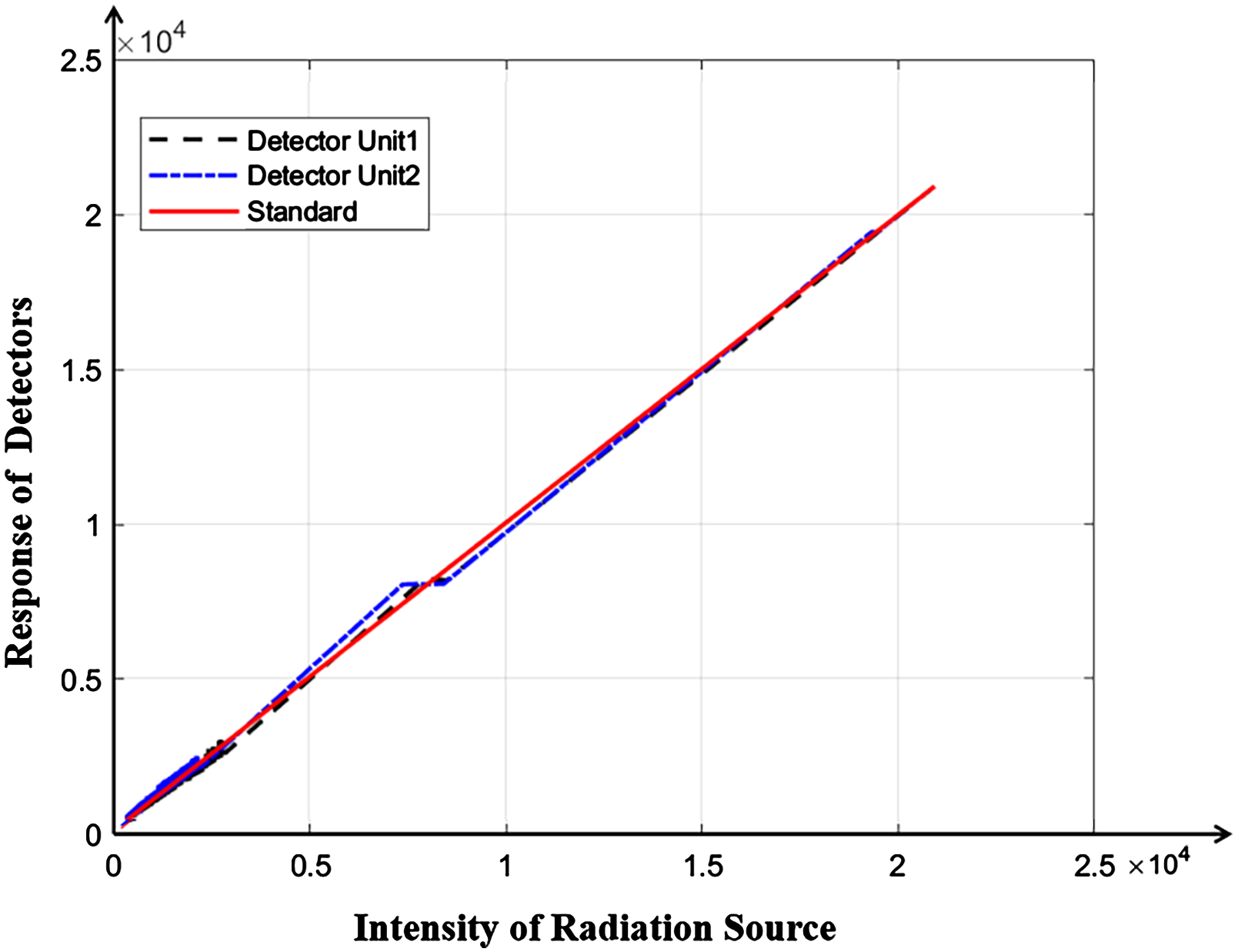
As illustrated in Figure 2(a), the sinogram displays each row of pixels corresponding to the signals captured by distinct detector units along the detector array line for a single projection angle. In contrast, each column of pixels corresponds to the signals gathered by a single detector unit across multiple projection angles. Consequently, the variations in the response of adjacent detector units to similar ray intensities can cause certain columns in the sinogram to exhibit anomalies, manifesting as pronounced stripe artifacts. Ultimately, during the FDK (Feldkamp-Davis-Kress) 18 image reconstruction process, the back-projection of these anomalous detector response signals along the circular trajectory at various angles leads to the formation of ring artifacts in the reconstructed CT image.
Artifacts in sinogram and CT image.
Detector-response correction method
Based on the above analysis, it can be seen that the fundamental cause of the ring artifact is the inconsistency and nonlinearity of the response function of the detector units. Thus, it is inferred that the ring artifact can be physically eliminated by correcting the response function of each detector unit to a consistent linear function according to the actual dose.
To scale the response function, we need to obtain the response value of the detector unit to different intensities of rays. However, the detection system uses an isotope ray source with non-adjustable intensity, a Co-60 source, to ensure that the rays can penetrate large components. In this case, the intensity of the rays received by the detector can only be adjusted by changing the thicknesses of the absorber with known ray attenuation coefficients.
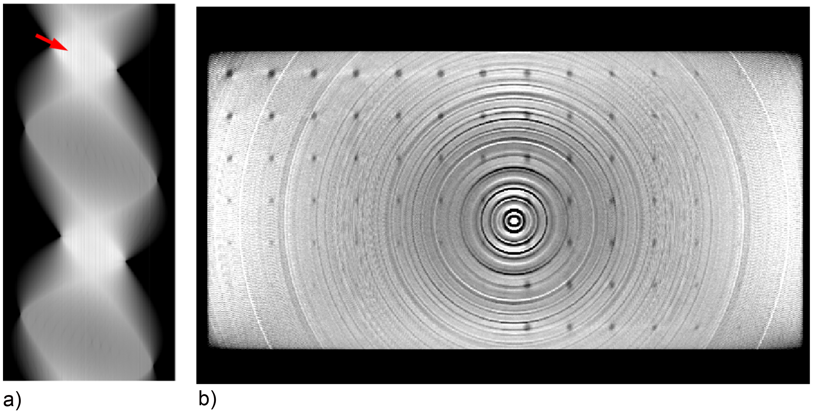
As the core supporting structural components of high-temperature reactors, the nuclear graphite/carbon bricks inherently have the characteristics of a single material, uniform density, and known geometric shape, which means that the ray attenuation ability of the tested component is determined. That is to say, prior knowledge of components can fortunately be used to calibrate the response functions of the detector units. As shown in Figure 3, the specific steps are as follows:
Obtain the raw projection data through scanning. Pre-reconstruct the original image with ring artifacts based on the raw projection data. Binarize the original image with the known shape and density of the component to be inspected to obtain its volume data. Use the volume data to generate theoretical projection data at different angles through the numerical simulation of the forward projection process. Process the raw projection data to discard the outliers and obtain high-quality processed projection data. Derive a fitting formula between the theoretical and the processed projection data through polynomial fitting. Use the fitting formula as correction functions to correct the raw projection data, thus solving the nonlinearity and inconsistency of detector response. Reconstruct CT images using corrected projection data.
Proposed Ring artifact reduction method.
Experiment
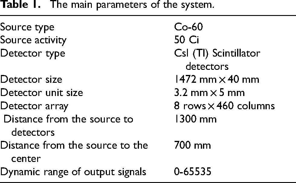
To verify the feasibility of our artifact reduction method, a scanning experiment of high-temperature graphite samples was carried out using the multi-row cone beam CT detection equipment below. As shown in Figure 4, the target graphite component was placed on the platform at the center hole of the turnplate. The source and the detector are fixed on the opposite sides of the turnplate, spiraling around the component. The CT detection system was developed by the Institute of Nuclear and New Energy Technology, Tsinghua University. The specific acquisition parameters are listed in Table 1.

Helical CT system.
The main parameters of the system.
The component to be inspected for experimental verification is a rectangular graphite brick of 296 mm*592 mm*60 mm. As shown in Figure 5, a series of circular through holes of different diameters are machined inside the component to simulate real defects. In this experiment, the scanning data of the component was obtained at a scanning speed of 4 min/r, collecting projection data of 1000 different angles.

Diagram of the inspected graphite component.
Results
This section compares and analyzes the ring artifact correction effect of three approaches, including the method of this paper, the traditional filtering method, and the machine learning method. After 10 years of service, the scintillator detectors have deteriorated due to a large amount of irradiation. As shown in Figure 6, due to the nonlinearity and inconsistency of the ray intensity response between different detector units, multiple distinct stripe artifacts can be seen in the sinogram Figure 6(a), which result in severe ring artifacts in the reconstructed CT image Figure 6(b).

Correction results of different methods.
Traditional filtering method
Most existing post-processing methods convert the reconstructed images into polar coordinates or Fourier domains, in which artifacts appear as stripes and can be removed by filtering. The traditional filtering method uses a low-pass filter to reduce the differences between detector units, thus correcting the projected data with artifacts. Since feature details in components also manifest as high-frequency differences between detector units in projection data, they may be affected by the filtering process.
As shown in Figure 6(c), the stripe artifacts of high frequencies in the sinogram are slightly suppressed after being processed by the low-pass filter, but not eliminated. Consequently, several annular artifacts still exist in CT image Figure 6(d) reconstructed with Figure 6(c). In addition, compared with the original reconstruction image Figure 6(b), the defect details in Figure 6(d) are somewhat blurred due to filtering.
Machine learning
Unlike filtering methods, the machine-learning method does not process projection data but directly corrects reconstructed images by training a network model. As we all know, the basic principle of image reconstruction based on the machine learning method is to input a large number of training data in pairs of deteriorated images vs. clean images to the model, so that the model can learn the law of deterioration, and then obtain the ability to reconstruct the image. Unfortunately, as the artifacts originate from the abnormal response of the detector units that cannot be replaced, it is impossible to generate clean images without ring artifacts from experiments.
We have employed the fully open-source Monte Carlo simulation software GEANT4 (GEometry ANd Tracking)
19
to build a numerical simulation experimental model and to perform simulation experiments. Through this endeavor, we have adeptly captured projection data under standard detector signal conditions, leading to the production of pristine images that are free from ring artifacts, as shown in Figure 7(a). Capitalizing on this foundation, we have further developed the capacity to simulate projection data for situations where the detector response is abnormal, employing the formula detailed below:

Training dataset examples and the test result of the model.
Figure 7(a) and Figure 7(b) present a pair of training dataset examples consisting of a clean image and a corresponding image with ring artifacts. We generated 4000 pairs of datasets in total through Monte Carlo simulation. Then we trained a model using FBPconvnet, 20 one of the forward networks in CT image processing. Figure 7(c) is the corrected image of Figure 7(b), and there are no obvious ring artifacts in Figure 7(c), which proves that the model is valid for simulated images.
After the model was trained completely, it was used for image correction. As Figure 6(e) shows, the ring artifact correction result using the machine learning method is not as good as expected. The image is over-smoothed, resulting in the complete disappearance of small holes in the image after correction. Perhaps due to the inability to produce high-quality datasets that are sufficiently realistic, the machine learning method did not work.
Proposed method
This paper proposes a new method of ring artifact correction based on the generation mechanism of ring artifacts. We use the prior information on graphite components to calibrate each detector unit's ray intensity response function by pre-reconstruction. Eventually, the ring artifact is physically eliminated based on the solved detector response model.
Figure 6(f) presents the CT sinogram corrected by our method, in which the stripe artifact is almost eliminated. Therefore, the ring artifact in the reconstructed image Figure 6(g) is also corrected. Furthermore, compared with the previous two methods, the defect details in the CT images processed by our proposed method are better preserved.
Analysis
To quantitatively analyze the ring artifact correction effect of different image restoration methods, we use ring total variation (RTV) as the evaluation index of the deterioration degree of ring artifact: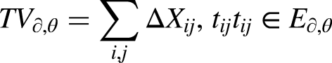

The sum
The value of RTV can reflect the image's grayscale on the polar coordinates. Since the ring artifact is a concentric ring centered on the center of the image, it will cause the image's grayscale to change drastically in the polar radial direction. That is, the more severe the ring artifact in the image, the greater the value of RTV.
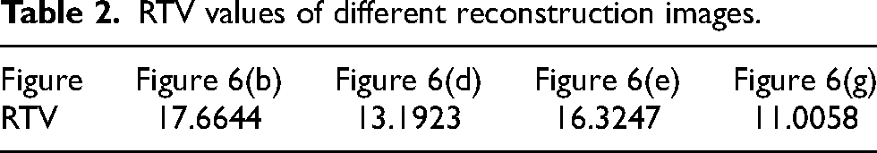
Table 2 lists the RTV value of the corrected image by different correction methods. Results show that the RTV value of Figure 6(g) is the smallest, which means that the correction effect of the proposed method is the best. Experimental results show that the proposed method performs better than the traditional filtering method and machine learning method in ring artifact suppression and image original detail preservation.
RTV values of different reconstruction images.
Our results demonstrate that the essence of the ring artifacts in the CT images of graphite components is the abnormal responses of the detector units. Methods such as filtering and machine learning which merely process projection or image at a holistic level only have a slight suppressive effect on artifacts, while not conducive to the reconstruction of image details. Although the ring artifact has the common shape characteristics of concentric circles, the specific performance of artifacts varies depending on the degree of deterioration of the detector unit. Therefore, solving the response functions of the abnormal detector units is an excellent method to reduce ring artifacts, especially when the prior knowledge of the object to be inspected is abundant.
Conclusion
In this study, the detector units’ response functions are solved using the prior knowledge of the graphite component. The abnormal responses caused by irradiation are fundamentally corrected. The proposed method reduces ring artifacts and successfully preserves the image details and textures. Thanks to better CT images of the components, the defect recognition capability of the system is improved, which ensures the long-term stable operation of the detection system and also benefits the safety of HTGR.
Footnotes
Funding
The authors received no financial support for the research, authorship, and/or publication of this article.
Declaration of conflicting interests
The authors declared no potential conflicts of interest with respect to the research, authorship, and/or publication of this article.