



Abstract
This study, based on preeminent characteristics of both the pneumatic and hydraulic isolations, combined hydropneumatic isolations (CHPIs), is proposed for improving the cab ride quality of the vibratory rollers in low-frequency domain. A 3D dynamic model and mathematical model of the cab isolations and the vibratory rollers are established to simulate CHPI’s characteristics under the excitations of the off-road terrain and vibratory drum at 28 Hz and 35 Hz. To enhance the reliability of research results, vehicle’s mathematical models are also verified via the experimental investigation. The effectiveness of CHPIs on ameliorating the cab’s ride quality is then analyzed via two indicators of the power spectral density (PSD) acceleration on the frequency region and root-mean-square (RMS) acceleration on the time domain of the cab and operator seat. It is found that with the combination of the high-elastic stiffness parameter and high nonlinear damping coefficient of CHPIs using for the vehicle’s cab isolations, the results of the cab’s ride quality are greatly improved compared with other cab isolations in the well-known existing works.
Introduction
Under the working conditions of vibrating rollers on deformed terrains, the generated vibration sources from the interaction between the vibrator drum/tires and terrains had been directly transmitted to the operator through the cabin isolation mounts and operator’s seat suspension.1-4 Moreover, excitation vibrations under low frequencies of 0.5–10 Hz caused by off-road soil surface roughness severely influenced the operator’s physical health.5-6 Thus, the operator’s ride quality was greatly affected by deformable soil grounds.
To reduce the influence of off-road terrains on the operator’s ride quality, cab isolations were thus particularly interested. Traditional rubber isolations (TRIs) mainly used in cab isolations of vibratory rollers4,7 were optimized to ameliorate the ride quality.4, 8 The scholars indicated that the optimized TRI was also very arduous to ensure the ride quality under low-vibration excitation frequencies due to the TRI’s low damping characteristic. Especially, the vibrations of the vertical operator and cab angles were very large under different operating conditions. To solve this problem, the hydraulic isolations (HIs) with high nonlinear damping characteristic9-10 were added in the TRI 3 . Three cab isolations including TRI, 11 HI, 12 and pneumatic isolation (PI) had been applied to evaluate on the isolation performance of the vibratory roller cab. 13 Based on optimal fuzzy PID controllers, HI’s damper forces were then optimized and controlled to enhance the cab’s ride quality.8, 14 It was found that the vehicle’s vibrations were significantly improved under both domains of frequency and time. However, research studies also indicated that power spectral density(PSD) acceleration responses of cab’s pitching angle and operator’s seat heave were still high under low-excitation frequencies, especially below 4 Hz. Thus, the operator’s health and safety were seriously affected under off-road terrains.
The PI with its nonlinear damping parameters and high-elastic/static stiffness parameters were widely employed on the cabin’s suspension systems of vehicles to ameliorate the ride quality and decrease noise.15-17 A hybrid suspension system of the hydropneumatic suspensions (HPSs) was used for dump trucks and agricultural tractors to ameliorate the ride quality and reduce the energy.18-19 The results revealed that the operator’s ride quality was remarkably increased with HPSs. Although the impact of off-road terrains on vehicle’s ride quality with HPSs had not yet been analyzed, however, the result of HPSs was an obvious basis to apply for cab isolations of vibratory rollers.
In this research, based on advantages of the HI and PI, a combined hydropneumatic isolations combined by hydro and pneumatic isolations is proposed for ameliorating the cab’s ride quality. A mathematical model of vibratory rollers working on off-road ground terrains and excited by the vibratory drum at 28 Hz and 35 Hz is established; concurrently, its mathematical model is also verified via the experimental investigation with the TRI. The PSD acceleration in the frequency region and root-mean-square(RMS) acceleration in time domain of the cab and operator seat are objective studies. The research results are then compared with the TRI to evaluate the CHPI’s effectiveness.
This study’s innovation is that using a 3D dynamic model of vibratory rollers to fully assess the cab’s pitching and rolling vibrations under off-road terrains. The CHPI with characteristics of high-elastic stiffness and nonlinear damping are proposed and studied to enhance the cab’s ride quality in low-frequency domain. Two indexes of RMS and PSD accelerations are concurrently used to assess the influence of vibrations on the ride quality, health, and safety of the operator.
Material and method
Mathematical model of off-road vibratory rollers
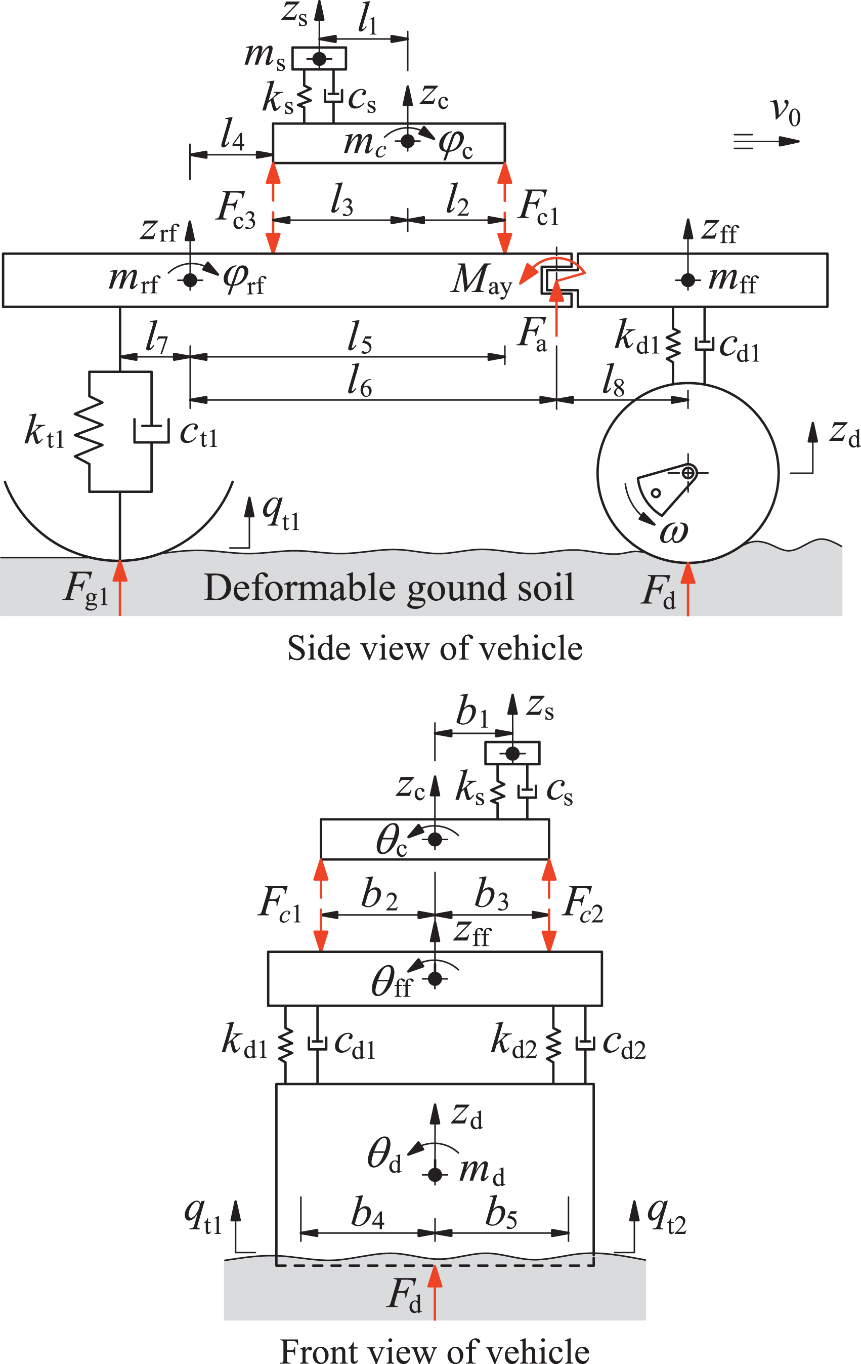
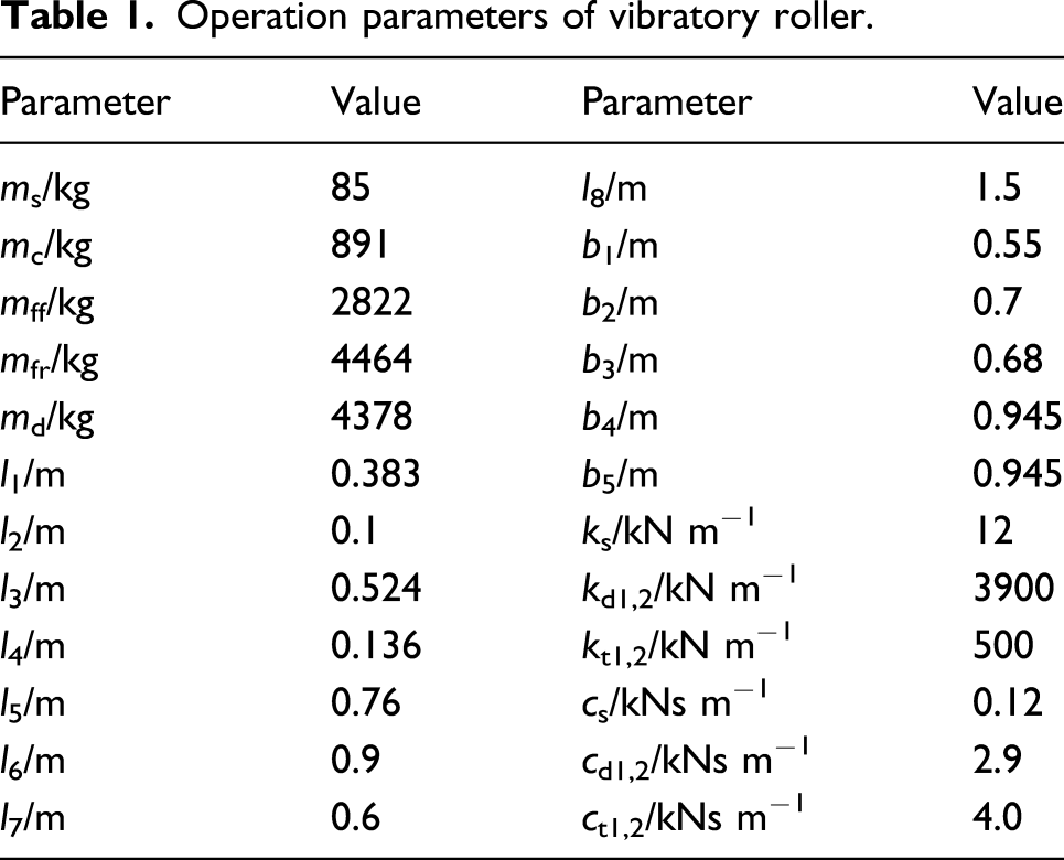
The vibratory roller’s structure mainly consists by operator’s seat, cabin, vehicle bodies, drum, and wheels. The cabin floor is isolated from the rear vehicle frame through four vibration isolations, as shown in Figure 1. Thus, a 3D dynamic model of the vehicles has been built for simulating cab isolations, as seen in Figure 2 where m
χ
is the mass of operator seat, cabin, rear frame and engine, front frame, and drum (χ = s, c, rf, ff, and d), respectively. zs is the vertical operator seat vibration. zc, φc, and θc are the vertical, pitching, rolling vibrations of the cabin. zrf, φrf, and θrf are the vertical vibration, pitching, and rolling angles of the rear frame, respectively. zd, θd and zff, θff are the vibration heave and roll of drum and front vehicle body. cs, ks and cdj, kdj are coefficients of damping and stiffness of operator seat suspension system and drum’s rubber isolations. l
α
and b
β
are distances of vehicle’s horizontal and width. qtj are excitations of off-road terrain under wheels (α = 1, 2, ..., 8, β = 1, 2 ,..., 5, j = 1, 2). Schematic of an actual vibratory roller. Mathematical model of the vehicle.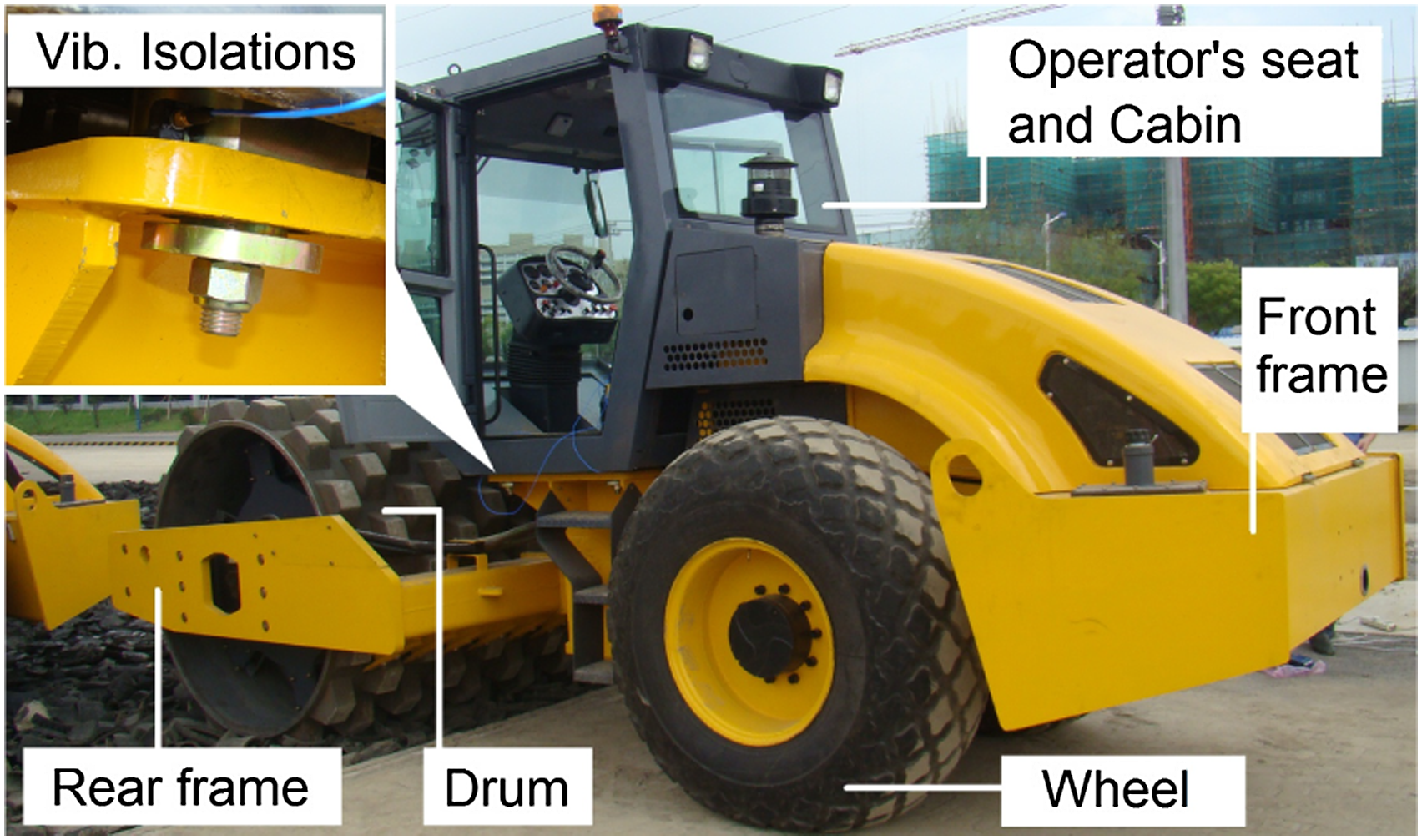
From the mathematical models of the vehicle and cab shown in Figure 2, their motion equations are written based on Newton’s II law as follows
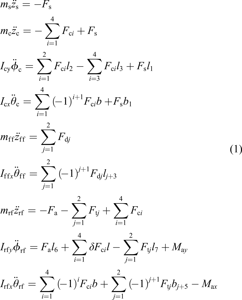

The vertical force responses in equation (1) including Fs, Fci, Fdj, and Ftj are, respectively, determined as follows The dynamic force Fs of the operator’s seat suspension is written as follows 2. The vertical force responses Fci of cab isolations are calculated in Section 2.2.

Loading phase and drum-hop phase
3. The excitation forces Fdj of the rigid drum-elastoplastic soil interaction (RD-ESI).
According to the study of Adam and Kop,
2
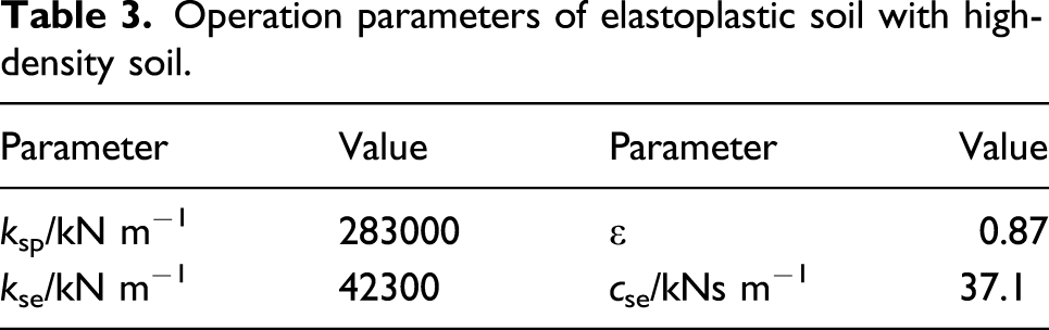
the elastoplastic soil (ES) was characterized by the elastic damping constant cse and plastic and elastic stiffness constants ksp and kse. Thus, the RD-ESI model is established to determine Fdj, as shown in Figure 3, where me and m are the mass of rotating eccentric and total mass of the vibrator drum and front vehicle body, respectively. zd and zse are displacements of drum and elastic soil deformation in the vertical direction. Fg is the reaction force of plastic deformation generated by the soil layer. Fe = meω2e sinωt is the force heave of the eccentric mass in the rotating direction. ω and e are rotational speed and eccentricity of me. la is the static equilibrium line. g is the gravitational acceleration. Model of the rigid drum-elastoplastic soil interaction.
During soil compaction, over each cycle of the RD-ESI, the drum motion on a soil patch may appear in two or three phases of loading phase, unloading phase, and drum-hop phase. To determine zd and Fdj, the vibration equation of the RD-ESI 4,20 is described as follows
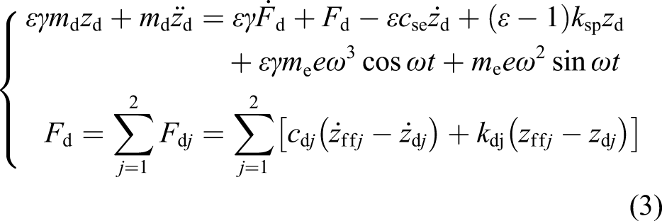


Equations (3)–(5) are then applied to calculate the parameters of zd and Fd. 4. Excitation forces Ftj of the elastic tire-deformable soil contact (ET-DSC).
The contact of the elastic tires and off-road terrain with the random surface also yields vibrations; thus, the ET-DSC model shown in Figure 4 is used to determine Ftj. Model of the elastic tire-deformable soil contact .
When the tire travels on off-road terrains with roughness surface q(t), the soil ground is sunk by zoa due to the impact of the tire dynamic and static load of vehicle. Two deformable characteristics including one of the tire-soil deformation (c’oc-region) and another one of the unique soil (ca-region) are thus described as in Figure 4. In the deformable regions of c’oc and ca, both the generated pressure px and shear stress τx impact on the tire. Fg generated by off-road terrain and tire interaction is written as follows

Both τx and px determined in
1
are given as

Assuming that an average line l
a
is representative of the roughness surface of terrain, so the sunk solid zx is determined by

The excitation q(t) is calculated as follows.
Based on ISO/TC108/SC2/WG4 N57
21
of deformable terrain surfaces, their spectral densities are given by

At a constant speed v0 of the vehicle traveling, the terrain surface roughness is simulated as follows

The different values of G(m) for unpaved off-road levels including levels from very good to poor were given by Mitschke.
22
Thus, q(t) in equation (10) is created by selecting a value G(m) of Mitschke. From the mathematical model of the vehicle shown in Figure 2 and ET-DSC model shown in Figure 4, the excitation forces Ftj are given by

Model of cab isolation systems
With the design and optimization of TRI2-4, 8 in Figures 5(a) and (b) and its mathematical model with the linear damping and stiffness coefficients (cr and kr) shown in Figure 5(c), the TRI’s vertical dynamic force is described by Structure and model of cab isolations. (a) Traditional rubber isolations, (b) optimal rubber isolation, and (c) its mathematical model.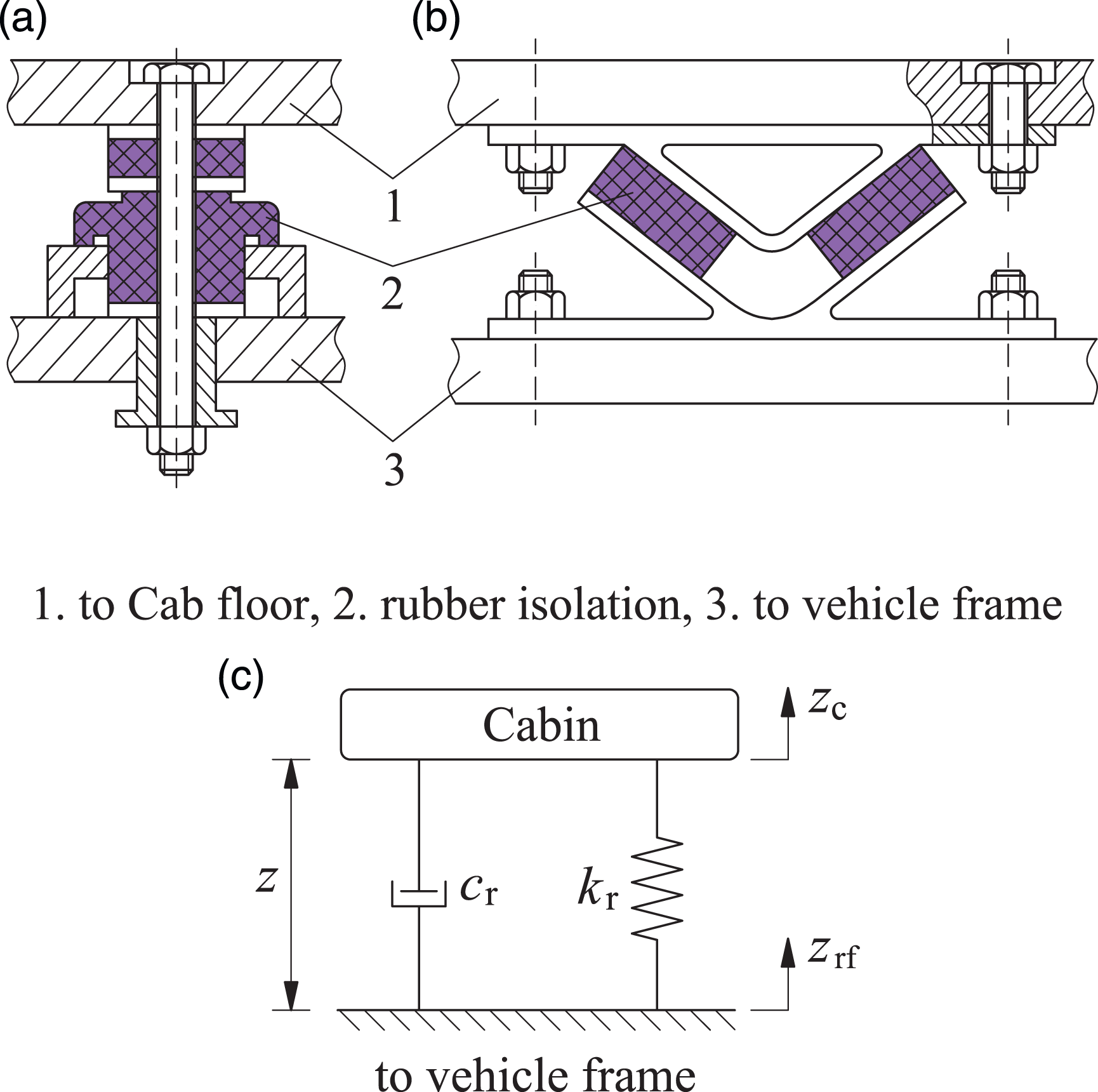

Because of the TRI’s effectiveness on improving the cab’s ride quality was very low,2-4 this study proposes the CHPI based on advantages of the HI and the PI9-10, 12, 15 to further ameliorate the cab’s ride quality of vibratory roller. The CHPI’s structure includes the airbag and air reservoir connected by the air pipe system, a fluid chamber, and a damping plate in fluid chamber driven by the bolt. The liquid flows in upper/lower chambers are led by the damper plate’s transfer via both the orifices and the annular orifice in the HI. Thus, the structure and dynamic model of CHPI are described in Figures 6(b), where ch is the HI’s nonlinear damping constant, ke and kv are the PI’s static and viscous stiffness coefficients, and M and c
β
are the mass and nonlinear viscous damper coefficient of the airbag. (a) Combined hydropneumatic isolation structure and (b) its mathematical model.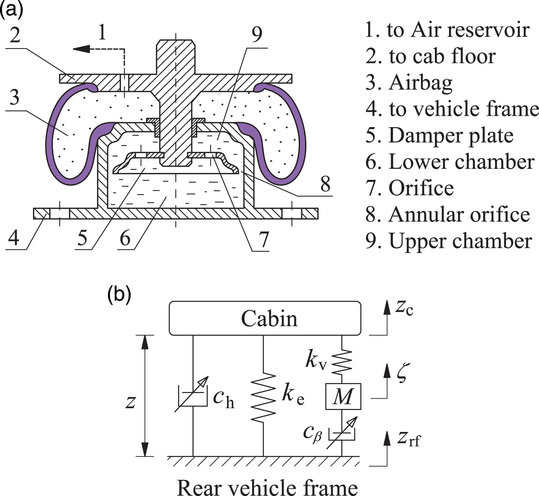
Based on the calculation result of the HI in 8–10, its liquid damping force is given by

Similarly, with the PI, the airbag is assumed to deform only in the z-direction, and the initial volumes of the airbag and reservoir are Vb0 and Vr0, respectively; therefore, the reservoir and airbag volumes after deformation are defined by

Based on the calculation result of the dynamic parameters of the airbag in
15
, the parameters ke, kv, and M, respectively, are determined as follows

Therefore, the airbag’s viscous and static forces in the z-direction are calculated by
23

The vertical airbag’s dynamic force Fb from equation (16) is then inferred by

By combining Equations (13) and (17) of the HI and PI, the CHPI’s dynamic force is written as follows

At each mount i of cab isolations, the dynamic force Fci can be rewritten as follows



Simulation and analysis of results
Efficiency indicators
The isolation effectiveness of suspension systems was mainly assessed via three indexes working space, ride quality, and road friendliness, in which the ride quality index assessed via RMS acceleration was one of the most important indexes.8, 24 On the other hand, according to ISO 2631, 25 PSD acceleration is given to evaluate human’s endurance that confines under excitation vibrations at low frequencies. ISO-2631-1 emphasized that the operator’s safety and health were greatly affected by the vibrations at a frequency range below 10 Hz.
Consequently, this study, the CHPI’s effectiveness at the low-frequency region is compared with TRI through the values of PSD and RMS of operator’s seat, cab pitching angle, and rolling angle. Both smaller values of PSD and RMS with corresponding isolations mean that its vibration isolation effectiveness is better, and RMS accelerations are described as follows

Experiment of vibratory roller
Operation parameters of vibratory roller.
Operation parameters of cab isolation systems.

Note: TRI: traditional rubber isolation; CHPI: combined hydropneumatic isolation.
Operation parameters of elastoplastic soil with high-density soil.
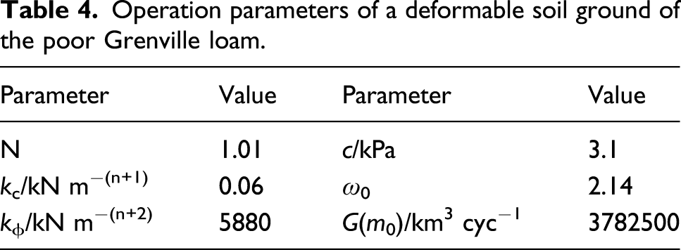
Operation parameters of a deformable soil ground of the poor Grenville loam.
The ICP acceleration sensors in three directions are used to measure accelerations at four positions of isolations on the cabin floor (ac1-4) and operator’s seat (az), as shown in Figure 7(a) and (b). Through the LMS dynamic test and analysis system of the signal processor, datum is calculated and given in the same Figure 7(c), and the acceleration responses of the cab and operator’s seat are then displayed. Experimental arrangement of vibratory roller. (a) Cab floor accelerometer at four positions of isolations, (b) operator’s seat accelerometer, and (c) display measurement results.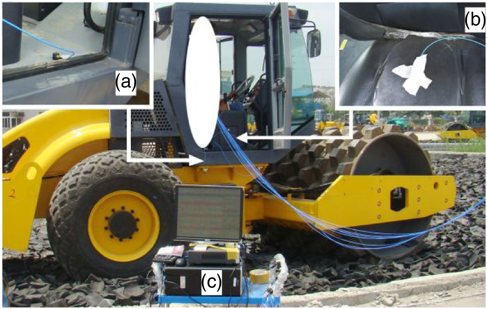
To determine the pitch and roll accelerations of the cab based on the measured accelerations in the vertical direction at four tested positions of cab isolations, it is assumed that the angular deformations of the cabin floor are very small and have negligible effect; therefore, the angular accelerations of the cab via its kinematic relations are calculated as follows 11, 13
The experimental PSD results of operator’s seat heave, cab’s pitching angle, and cab’s rolling angle are then compared with the simulated results, as illustrated in Figures 8(a–c). Result of frequency responses. (a) Operator’s seat heave, (b) cab’s pitching angle, and (c) cab’s rolling angle.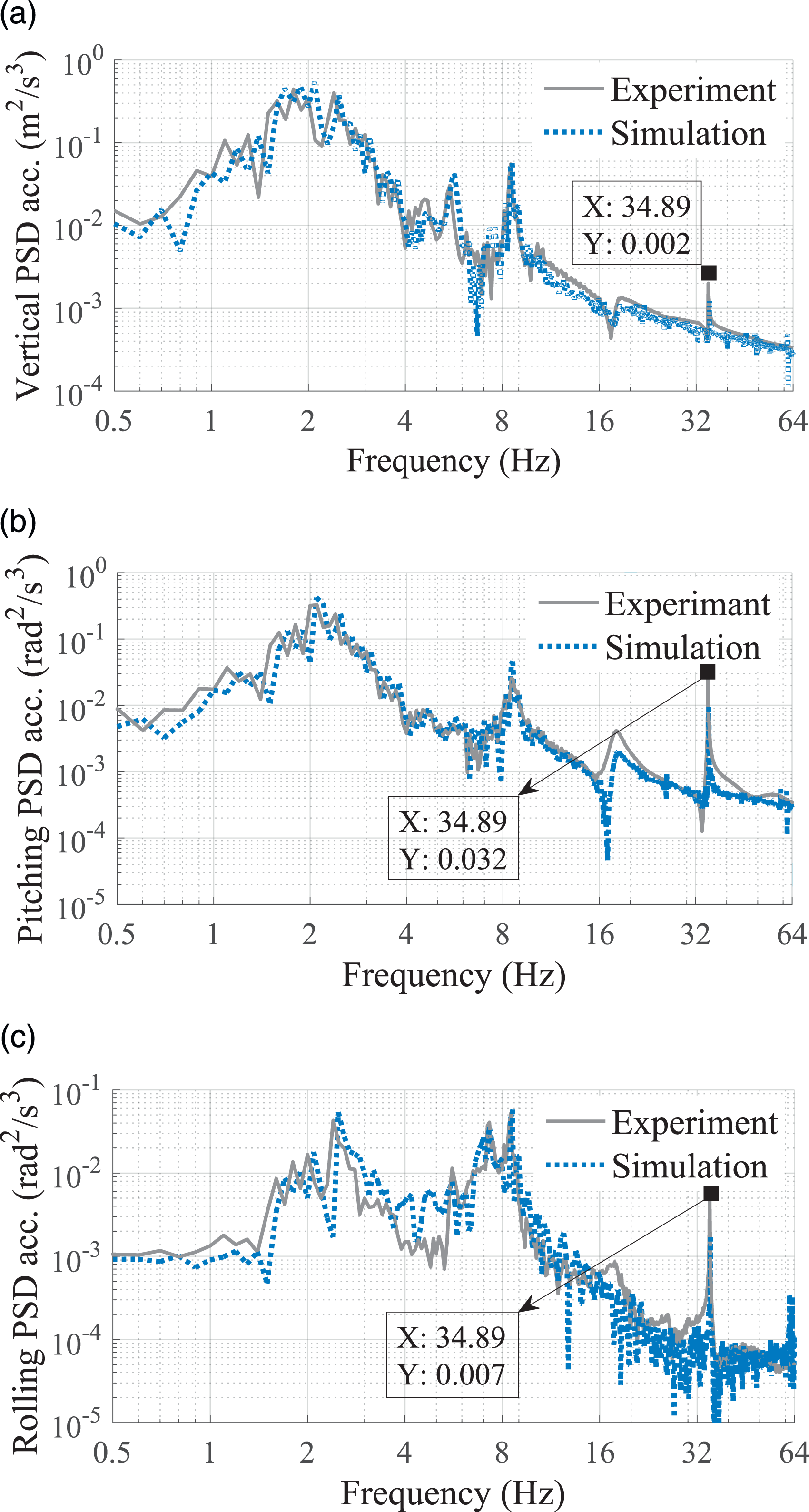
Observing Figure 8, it is found that the measured values are almost similar to the numerical simulation values under the same operating condition. A small change between the results of the experiment and simulation is also shown in the same Figure 8. These changes are ascribed to the dimension error of the vehicle and effect of the engine excitation in experimental process. However, the result error between the experiment and simulation is negligible. Therefore, the vibratory roller model with its operation parameters and deformable terrain can be relied upon to evaluate the CHPI’s effectiveness on ameliorating the cab’s ride quality.
Simulation results
Cab’s isolations equipped with CHPI for the vibratory roller is then simulated under the same experimental condition of TRI at low-/high-excitation frequencies 28 Hz/35 Hz of drum, and CHPI’s operation parameters have been listed in the same Table 2. Herein, the parameter kei of CHPI has been equivalently calculated with the parameter kri of TRI, while other parameters of CHPI have been calculated via the structure of CHPI, and the coefficient of chi is referenced in 8 . Both the maximum values of the PSD values and RMS values of operator’s seat heave, cab’s pitching angle, and cab’s rolling angle are used to evaluate CHPI’s effectiveness under the low-excitation frequencies.
Result in the frequency region
The PSD results at different excitations 28 Hz and 35 Hz of drum are plotted in Figures 9 and 10. Concurrently, their resonance frequencies are given in Table 5. The comparison results between TRI and CHPI in Figures 9 and 10 and Table 5 revealed that the PSD value of operator’s seat heave, cab’s pitching angle, and cab’s rolling angle with TRI has shown more peaks of the resonance than that of CHPI. Thereby, the high-density soil of the ES seriously impacts the operator’s health via the TRI. Conversely, the resonance peaks of PSD accelerations by using CHPI are reduced in comparison with TRI, particularly at resonance frequencies of 2.49 Hz, 5.69 Hz, 8.59 Hz, and 18.09 Hz. Besides, the resonance frequencies with the CHPI are changed compared with TRI in all directions. This is due to the change of coefficients Vb, M, and ρ of the air in airbag. Frequency responses at 28 Hz of drum. (a) Operator’s seat heave, (b) cab’s pitching angle, and (c) cab’s rolling angle. Frequency responses at 35 Hz of drum. (a) Operator’s seat heave, (b) cab’s pitching angle, and (c) cab’s rolling angle. Resonance frequency with cab isolations.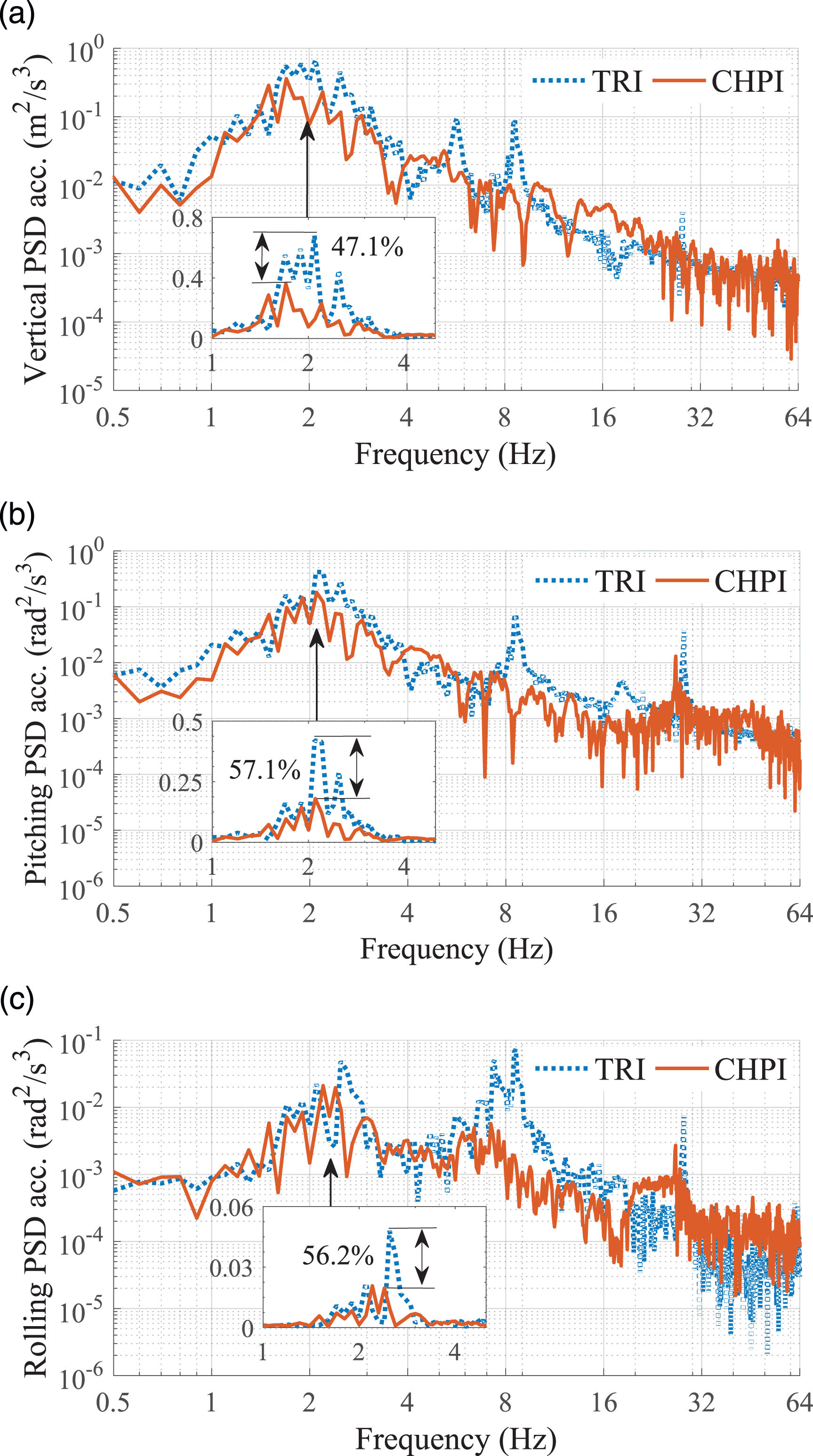

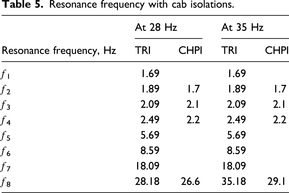
Under vibration excitations from 0.5 to 10 Hz, the PSD’s resonance peaks with CHPI are remarkably decreased at both the low and high frequencies 28 Hz and 35 Hz of the vibrator drum in all directions, especially at excitation frequencies below 4 Hz. The maximum values of PSD accelerations of operator’s seat heave, cab’s pitching angle, and cab’s rolling angle with CHPI are lower than that of TRI by 47.1%, 57.1%, and 56.2% at 28 Hz, and by 38.8%, 59.5%, and 64.8% at 35 Hz of the vibrator drum, respectively. These results can be due to the impact of CHPI damper forces
With the vibration excitations above 10 Hz, the PSD’s resonance peaks are also shown in the same Figures 9 and 10. The resonance frequencies with TRI also appear at 28.18 Hz under a low excitation and 35.18 Hz under a high excitation of drum. This has been ascribed to the influence of resonances at various excitations 28 Hz and 35 Hz of the excitation drum. Meanwhile, the PSD’s resonance peaks with the CHPI occur at 26.6 Hz and 29.1 Hz instead of at 28 Hz and 35 Hz of the excitation drum; concurrently, the PSD accelerations are slightly increased in comparison with the TRI. This particularity may also ascribe the impact of the parameter ke of airbags. However, the operator’s health is insignificantly affected in this frequency range. Therefore, it can conclude that the operator’s safety and health are remarkably ameliorated by using the CHPI under low frequencies in the condition of the vibratory roller traveling and compacting on the ES.
Result in the time region
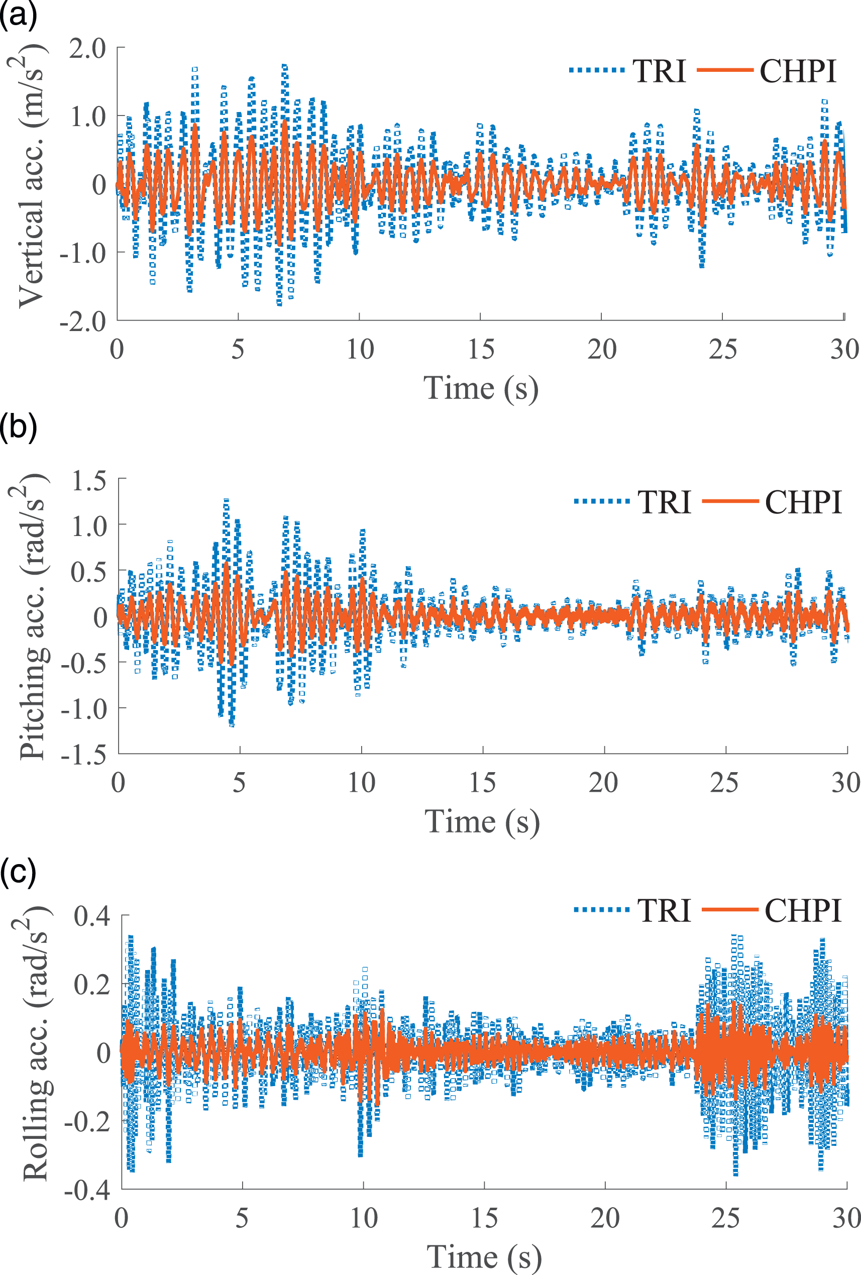
The accelerations of the operator’s seat heave, cab’s pitching angle, and cab’s rolling angle are also illustrated in Figures 11 and 12, respectively. The comparison results between TRI and CHPI in both Figures 11 and 12 indicate that the accelerations with the CHPI are smaller than that with the TRI at various excitations 28 Hz and 35 Hz of the vibrator drum at high-density soil of the ES. Acceleration responses at 28 Hz of drum. (a) Operator’s seat heave, (b) cab’s pitching angle, and (c) cab’s rolling angle. Acceleration responses at 35 Hz of drum. (a) Operator’s seat heave, (b) cab’s pitching angle, and (c) cab’s rolling angle.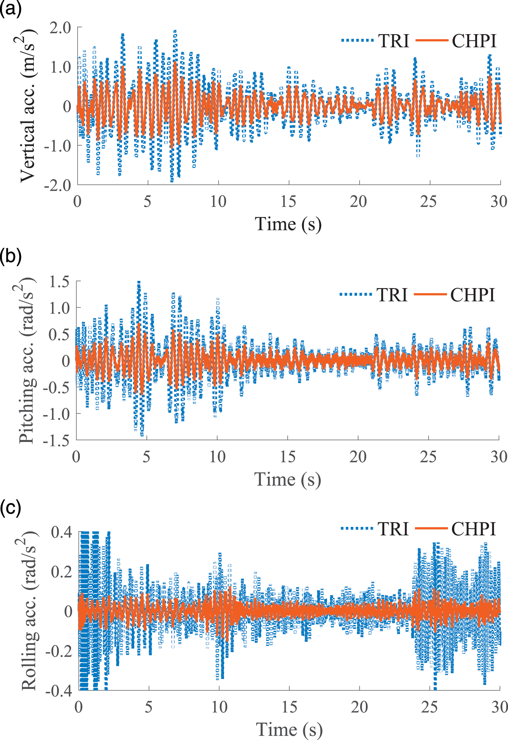
Additionally, the compared RMS values of operator’s seat heave, cab’s pitching angle, and cab’s rolling angle between TRI and CHPI in Figures 13(a) and (b) also revealed that their RMS values with CHPI are lower than that of TRI by 31.9%, 43.1%, and 49.2% at a low excitation of 28 Hz, and by 34.8%, 41.0%, and 52.2% at a high excitation of 35 Hz. It can be due to the influence of damper forces Fhi and Fβi of CHPI. Thus, the cab’s ride quality of vibratory roller can be ameliorated by using the CHPI. Root-mean-square accelerations of operator’s seat vibration and cab shaking. (a) At 28 Hz and (b) at 35 Hz of the excitation drum.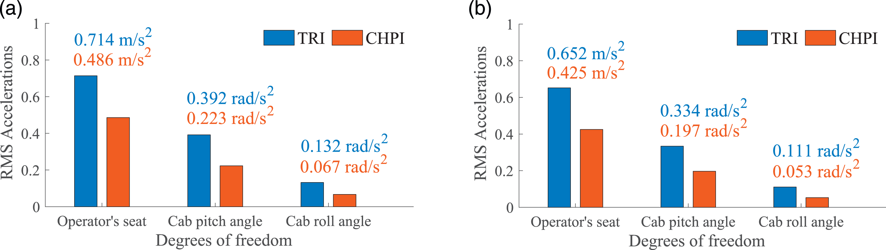
Comparison of RMS values with the different cab isolations at 28 Hz of the vibrator drum.
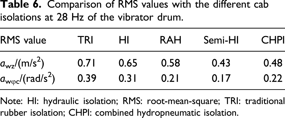
Note: HI: hydraulic isolation; RMS: root-mean-square; TRI: traditional rubber isolation; CHPI: combined hydropneumatic isolation.
Conclusions
The mathematical models of the vehicle and cab equipped with TRI are also tested under the same simulation conditions. The CHPI’s effectiveness is then simulated and assessed via two indexes of PSD and RMS accelerations of the operator’s seat vibration and the cabin shaking. The research results can be summarized as follows.
The results of PSD accelerations in the frequency domain and acceleration responses in the time domain with CHPI are lower than that of TRI under various conditions of low-/high-excitation frequencies 28 Hz/35 Hz of drum and the ES. Especially, the maximum value of PSD and RMS accelerations of operator’s seat, cab’s pitching angle, and cab’s rolling angle have been greatly reduced by 38.8%, 59.5%, and 64.8% and by 34.8%, 41.0%, and 52.2% at 35 Hz of the excitation drum, respectively.
The research results indicate that the CHPI with the properties of the high static stiffness and nonlinear damping obviously isolate the vibration under low frequencies and control cab’s pitching angle of the vehicle. Additionally, nonlinear damping parameters chi of the CHPI can be controlled to further enhance the isolation effectiveness of the CHPI.
Footnotes
Declaration of conflicting interests
The author(s) declared no potential conflicts of interest with respect to the research, authorship, and/or publication of this article.
Funding
The author(s) disclosed receipt of the following financial support for the research, authorship, and/or publication of this article: This work has been supported by the Science and Technology Research Project of Education Department of Hubei Province, China (No. B2020199), Teaching and Research Project of Hubei Polytechnic University, China (No. 2020C21), and Open Fund Project of Hubei Key Laboratory of Intelligent Transportation Technology and Device, Hubei Polytechnic University (No. 2020XY105).
