
Abstract
Under the impaction of excitation forces of the elastic tire/rigid drum and off-road soil ground interactions, the vibratory roller’s ride quality had been strongly influenced. Thus, the vibration isolation models and structures of the vehicle’s cabin and seat are studied and improved for enhancing the vehicle’s ride quality. To have an overview of the study and development process of the seat suspensions and cabin isolations, this research provides the overall view of the seat and cabin’s vibration isolation models developed and applied to the vibratory rollers based on the results of the existing studies. The study shows that with the semiactive hydraulic isolations (HIs) or semiactive pneumatic-hydraulic isolations (PHIs) applied to the cabin’s vibration isolations, the cabin shaking and driver’s ride quality have been remarkably ameliorated, while, with quasi-zero stiffness elements (QSE) added into the seat suspension, the driver’s ride quality has been greatly ameliorated. Based on the studied results, to control the cabin shaking and enhance the driver’s ride quality, a combination between the cabin’s semiactive HIs and the seat’s QSE should be developed in further studies.
Introduction
The vibratory rollers had been directly used to compact the pavements. To enhance the working performance of vibratory rollers, both indicators of ride comfort and compression efficiency are used to research and design vehicles. In order to ensure the comfort and compression efficiency of vibratory rollers under all different operating conditions, the investigation of the vibratory drum’s compression force, drum’s excitation, and road surface transmitted to the cabin and seat was especially concerned by designers. Vibratory roller designers are constantly working on improving the vehicle’s structure to achieve maximum compression force of the drum in all different terrains.1–5 Besides, researchers are also constantly developing new isolation systems for the cabin and seat to reduce the vibration of both the cabin and seat.6–9
In the traveling and compacting conditions of vibratory rollers on deformable soil grounds, the vibratory roller’s excitations were directly generated by the tire and vibratory drum interacting with the deformed soil grounds. All these vibration excitations were then transmitted to the driver through isolation systems of the cabin and seat.2,3,10–13 Therefore, to ensure the ride quality of the driver, with the isolation systems of the cabin and seat, their various models and structures are always studied and developed for isolating the vehicle’s vibration excitations.6,7,13,14
In the development process of isolation systems of the vibratory roller cabin, firstly, the traditional-rubber isolations (TRIs) using rubber materials were designed and applied. The structure of TRIs was also optimized to improve its isolation performance.4,6 Based on the research result of the hydraulic isolations (HIs) using the liquid damping force, HIs isolation efficiency was very good.15,16 Then, the cabin’s TRIs had been replaced by using HIs to decrease the seat’s vibration and cabin shaking.7,8 In order to further enhance the ride quality of the driver as well as decrease cabin vibration angles, the pneumatic-hydraulic isolations (PHIs), semiactive HIs, or semiactive PHIs had been also investigated and developed for the cabin’s isolation systems.8,9,17,18 Both the ride comfort of the driver and cabin’s shaking had been thus remarkably improved. However, the research also indicated that the seat’s acceleration response in the vertical direction was still high based on ISO 2631-1: 1997. 19 Thus, with the high efficiency of quasi-zero stiffness elements (QSE) embedded into vehicle’s seat suspensions for isolating the vibration of the driver,20–22 the QSE’s structure was then studied and applied for vibratory rollers' seat suspension for decreasing driver’s vibration responses. 7
From the obtained results of isolation systems of the vibratory roller’s cabin and seat in existing investigations, this paper reviews a summary of the development of the model and structure of isolation systems of the cabin and seat of vibratory rollers. Besides, from the analysis result of isolation systems of the cabin and seat, the research also gives some comments on the development trend of modern isolation systems.
Modelling of vibratory rollers
Vibratory roller’s structure and model
The vibratory roller has been designed with a vibratory drum, two elastic tires, front floor, engine and rear floor, cabin, and driver’s seat.3–7,12,13,23 The vibratory drum is connected with the front floor of the vehicle via the drum isolations, and the vibratory drum is used to create the compression force to compress the deformable terrains. Front and rear floors are connected via the articulation joint. The cabin’s isolation systems are used to isolate the vibration between the cabin floor and the rear floor. Similarly, the suspension system of the driver’s seat has been also used for isolating the vibration between the seat and the cabin floor. The model of an off-road vibratory roller is described in Figure 1. The interaction dynamic models of vehicle and off-road terrain surface.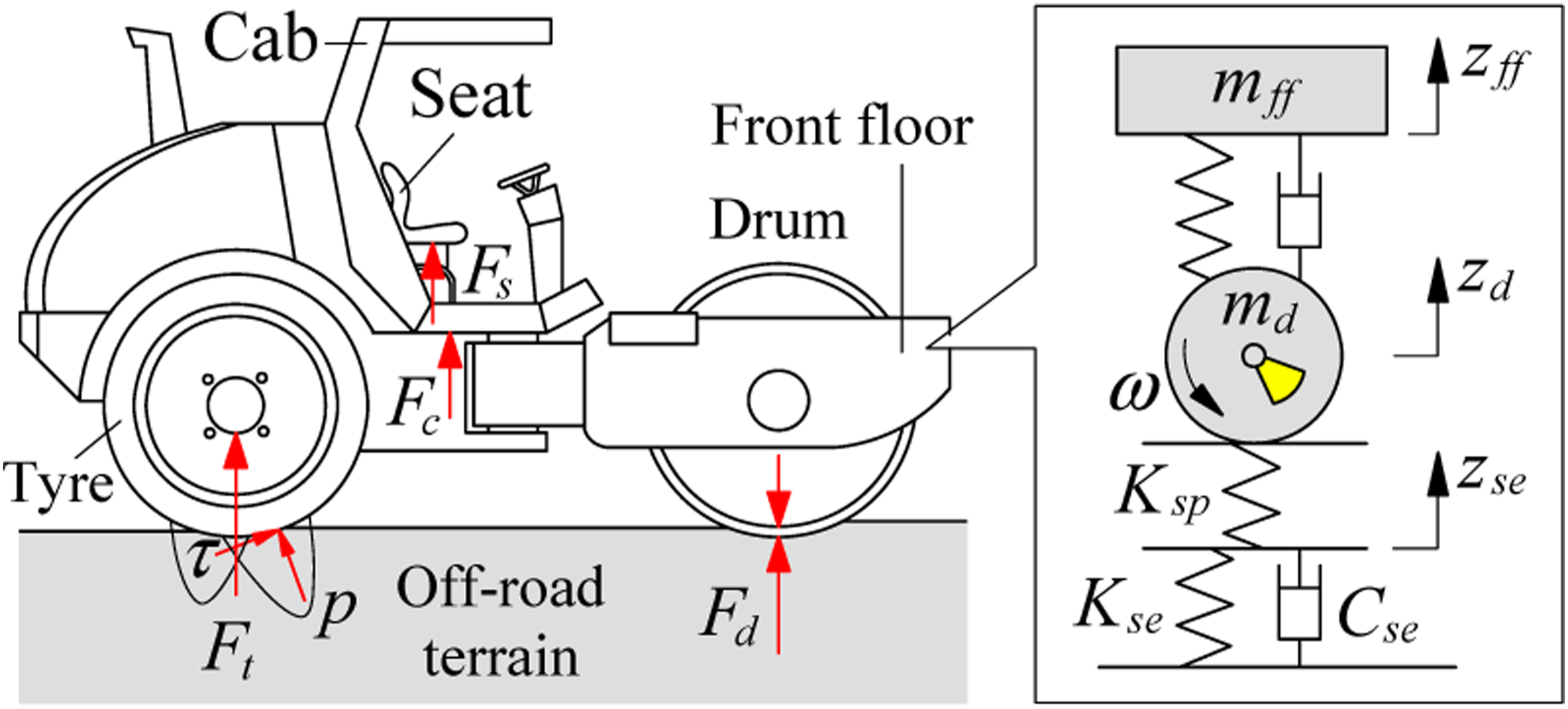
From the model of the vibratory roller plotted in Figure 1, its differential equations are expressed in the matrix form as

In the working condition of the vehicle on off-road soil surfaces, the compression force of the vibratory roller has been generated by a dynamic force of a rotating eccentric shaft of the drum combined with a static force of the vehicle mass to compress the terrain surface.3,11,23 Thus, the vibratory roller’s compression efficiency is directly affected by interaction forces between vibratory drum-terrain (F d ) and tire-terrain (F t ). In order to enhance the vehcile’s compression efficiency and increase soil ground’s densities in the working process, the interaction models and characteristics of interaction forces of drum/tire and off-road terrain grounds have been studied to optimize two force responses of F d and F t as follows.
Research of vibratory roller’s excitations
In order to enhance the off-road vibratory roller’s compression performance, the compression force F d of the vibratory drum interaction with the terrain ground should be evaluated and optimized. Thus, the interaction dynamic model between the vibratory drum and terrains has been established in the same Figure 1 to compute the elasto-plastic soil reaction force under the excitations generated by the vibratory drum.1–3,23,24
Because the deformed soil grounds are characterized by elasto-plastic properties when the vibratory drum of the vibratory is compacting on the off-road terrain, thus, Adam and Kopf gave an evaluation approach of the elasto-plastic properties of the deformed terrain ground based on the damping ratio of the soil ground (α) and plasticity factor of the soil ground (β) as23
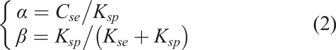
The terrain ground’s property is elastoplastic when the value β is 0 < β < 1. When β = 0, this means that K sp = 0 and the soil ground’s property is plastic. When β = 1, this means that K sp = ∞ and the soil ground’s property is elastic.
Based on the characteristics of the pressure and sinkge of the deformed terrain ground when the vibratory drum interacted with the off-road terrain surface,2,24 Adam and Kopf
23
assumed that over each cycle of the drum, there are two or three cases of the distinct phases presented as follows: Case 1-Loading phase, the vibratory drum has moved downward and the compression force of the drum has been applied to the soil ground. The soil ground’s property in this phase has been characterized by both elastic and plastic properties. Case 2-Unloading phase, the vibratory drum has moved upward and the interaction between the vibratory drum and the terrain surface has still existed. However, the soil ground recovers the elastic property whereas the plastic property represents the compaction of the soil ground and it is infinite (K
sp
= ∞). Case 3-Drum-hop phase, when the contact between the vibratory drum and terrain surface has been lost, the soil’s elastic property has been recovered whereas the plastic property is K
sp
= 0, thus, the value of β is also β = 0. To compute the soil ground’s reaction force F
d
in Figure 1, vibratory drum and elasto-plastic terrain’s interactions calculated via three phases are expressed as4,5,11
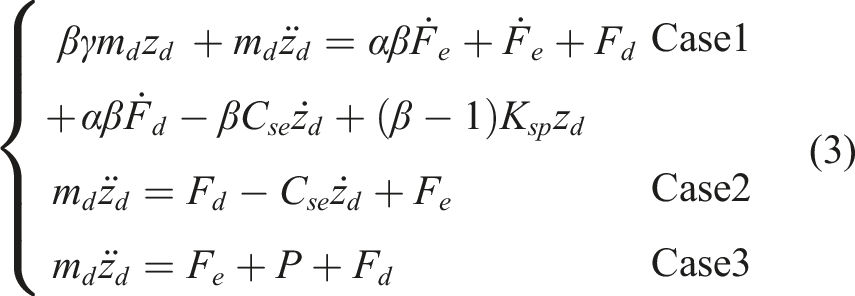

Based on the calculation result in the interaction process between the vibratory drum and elasto-plastic terrain ground in equation (3), the characteristics between the force F
d
and deformable z
d
of the vibratory drum vibration had been given in Figure 2.4,5,25 The ground’s deformation under the reaction of the drum.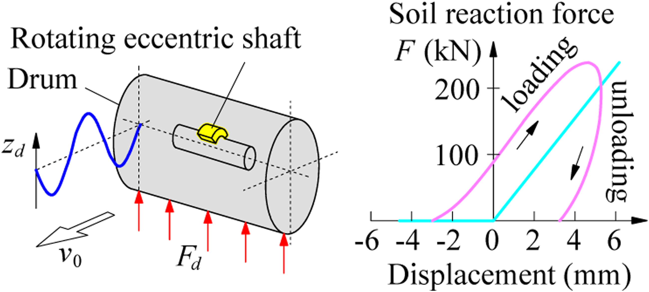
Based on the calculation result of the characteristics between F d and z d in Figure 2, to optimize the compression force as well as enhance the vibratory roller’s compression efficiency, the drum’s operation parameters had been optimized and controlled under various elasto-plastic terrain surfaces.1,3,25 Studies indicated that the vehicle’s compaction efficiency was remarkably ameliorated. But studies also emphasized that the compaction efficiency was strongly affected by the F d and its excitation frequencies. In order to reach the maximum F d , the different excitation frequencies of the vibratory drum from 0.1 to 70 Hz when the vehicle is compacting on the elastoplastic terrain surface had been simulated and analyzed.4,6,23,26 The research showed that the maximum F d could be obtained under excitation frequencies from 15 to 40 Hz.6,26 Especially at a low-frequency of 28 Hz and a high-frequency of 35 Hz of the vibratory drum, F d was maximum because of the vibratory drum’s double-jump.4,6,23 It implies that the vibratory roller’s compaction efficiency is good when the vibratory drum is working at low/high excitation frequencies of 28 and 35 Hz. However, under the influence of the maximum F d , the vertical and pitching accelerations of the seat and cabin are very great. This means that the vibratory roller’s ride comfort is strongly influenced by the excitation force F d . To improve the vehicle’s ride comfort, the interaction dynamic model of the vibratory drum and elasto-plastic terrain in Figure 1 had been directly applied to calculate the F d transmitted to the cabin floor.6,8,12,17,18
In addition, under the interaction of the tire and random road surface when the vibratory roller is traveling and compacting, the vehicle’s ride comfort was remarkably influenced.4–8 The vibration investigations of vehicles showed that when the vehicle is traveling on a rigid road surface, both indexes of the ride comfort and noise are strongly influenced.15,26–28 To reduce the vibration and noise generated by the contact of elastic tires and random road surfaces, various models of the tire-road contact such as the point-contact model, roller-contact model, fixed-footprint-contact model, radial-spring-contact model, flexible-ring-contact model, and finite-element-contact model had been proposed to optimize the dynamic force of the tire and road surface interaction.6,14,27
In the model of the point-contact, tires are modeled by the parallel-suspensions including spring and damper, as shown in Figure 3. The contact of the tire-road surface has been defined as point-contact. This could convert the road’s roughness to vertical vibration of the tire and calculate the dynamic of the tire.
27
In studies of the vehicle’s ride comfort, this model was widely applied to compute vertical forces of tires contacted with the road surface.27,28 Model and characteristics of elastic tire-rigid road interaction.
Based on the elastic deformation property of tires and the point-contact model of the tire-road surface (see Figure 3), the force-deformation response of the tire was defined by the compression process and recovery process. Thus, the force-deformation characteristic of the model had been calculated in equations (5−6) and described in the same Figure 3.
27

However, under the interaction of tires of the vibratory roller and deformable soil surface, the dynamic force of tires (F
t
) was affected by both terrain surface roughness and deformable terrain, especially with the soft terrain.7,10,12,14 Therefore, to calculate the F
t
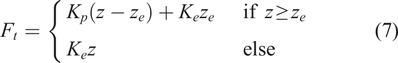
and evaluate the influence of the deformable terrain on the vehicle’s ride quality, the mathematical model of the elastic tire and soft soil ground contact was built to compute the elastoplastic property of the deformable road surface, as plotted in Figure 4.7,10,29,30 The dynamic model of the tire in contact with the soft terrain surface.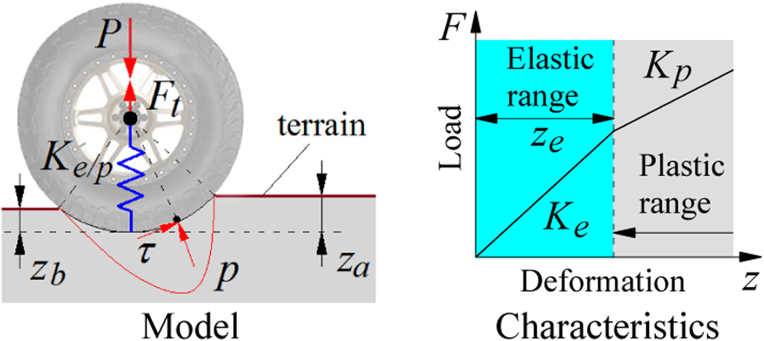
When the vibratory roller is traveling on the soft soil ground, due to the influence of the tire’s load static P = m
t
g, the soil ground has been deformed by (z
a
− z
b
). Two deformable properties of the terrain surface were defined by the plastic deformation with its plastic stiffness parameter (K
p
) and elastic deformation with its elastic stiffness parameter (K
e
). Therefore, the force-deformation characteristic of the tire and deformable terrain was calculated in equation (7) and described in the same Figure 4.
10
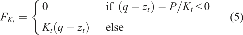
Also, the study result of Bakker and Wong indicated that under the influence of the tire’s load static, both pressure p and shear stress τ of the deformed soil ground affected the F
t
.29,31 Thus, a contact model between the deformable terrain and tire of vibratory rollers was built in Figure 5 to calculate the influence of p and τ on F
t
.13,14 The dynamic model of the deformable soil ground and elastic tire contact.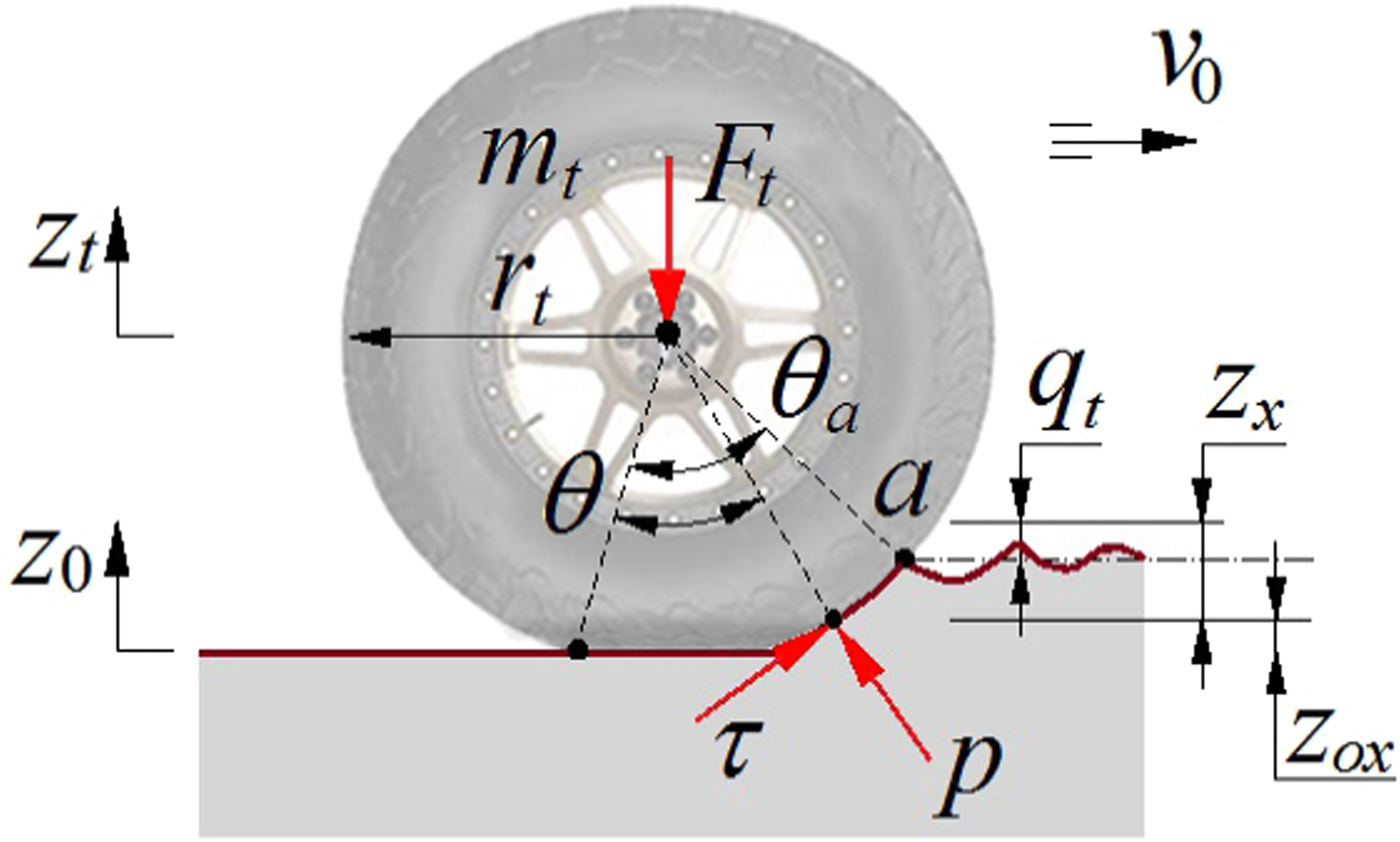
Under the influence of the deformable soil ground exerted on the elastic tire, F
t
was expressed as13,14
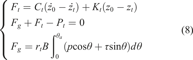
In order to assess the vibration of off-road vehicles and off-road vibratory rollers, the interaction model in Figure 5 was widely applied for calculating F t transmitted to the cabin floor.1,2,6–8,10,12,17,18,24
Based on the above research results, the low/high excitation frequencies 28 and 35 Hz of the drum had been applied to reach the max F d whereas both vertical force responses of F d and F t were calculated based on dynamic models of the vibratory drum/elastic tire interact with the off-road terrain surface to enhance the vibratory roller’s compression efficiency. However, the above research also revealed that both F d and F t strongly influenced the ride quality of the driver and the cabin’s shaking.4–8,10,17 Therefore, in order to ameliorate vibratory roller’s ride comfort, isolation systems of the cabin and the suspension systems of the seat are investigated and developed in the next part.
The research process of cabin isolations
Cabin’s traditional rubber isolations
In the design of vibratory rollers, in order to decrease the acceleration responses of both cabin and seat, isolation systems of the cabin had been used by the traditional rubber isolations (TRIs).4–7,9,23 The vibratory roller’s structure and cabin’s TRIs are plotted in Figure 6. Vibratory roller’s structure and cabin’s isolation.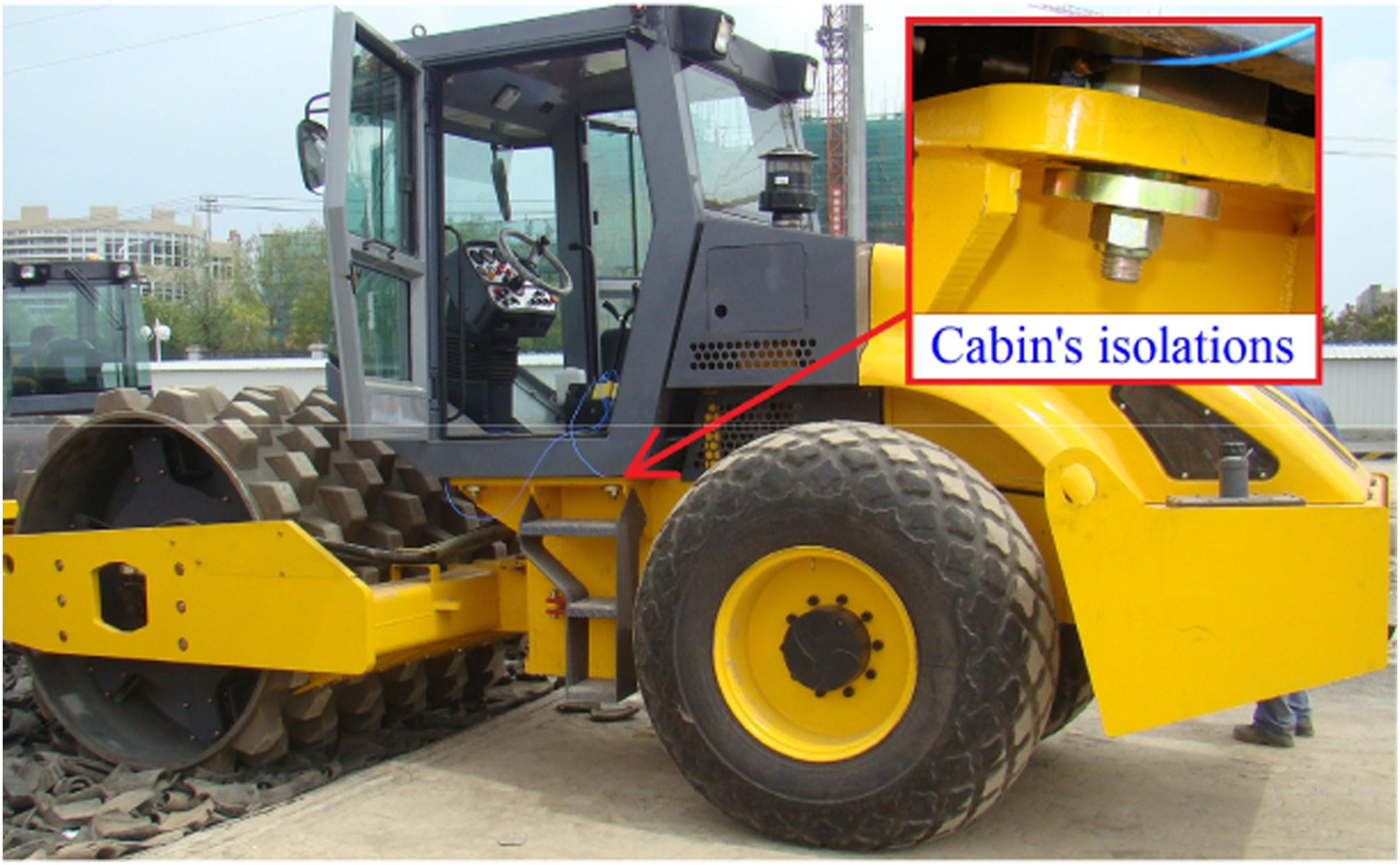
The traveling and compacting processes of the vibratory roller, both force responses F
d
and F
t
are generated by vibration excitations from the vibratory drum and terrain surface transmitted to the cabin. Therefore, the seat acceleration, cabin’s pitching acceleration, and cabin’s rolling acceleration are remarkably influenced. In order to decrease these acceleration responses, the TRIs of the cabin had been mainly used.4,5,23,24 The structure and dynamic model of TRIs have been exhibited in Figure 7. Model of cabin’s traditional rubber isolation.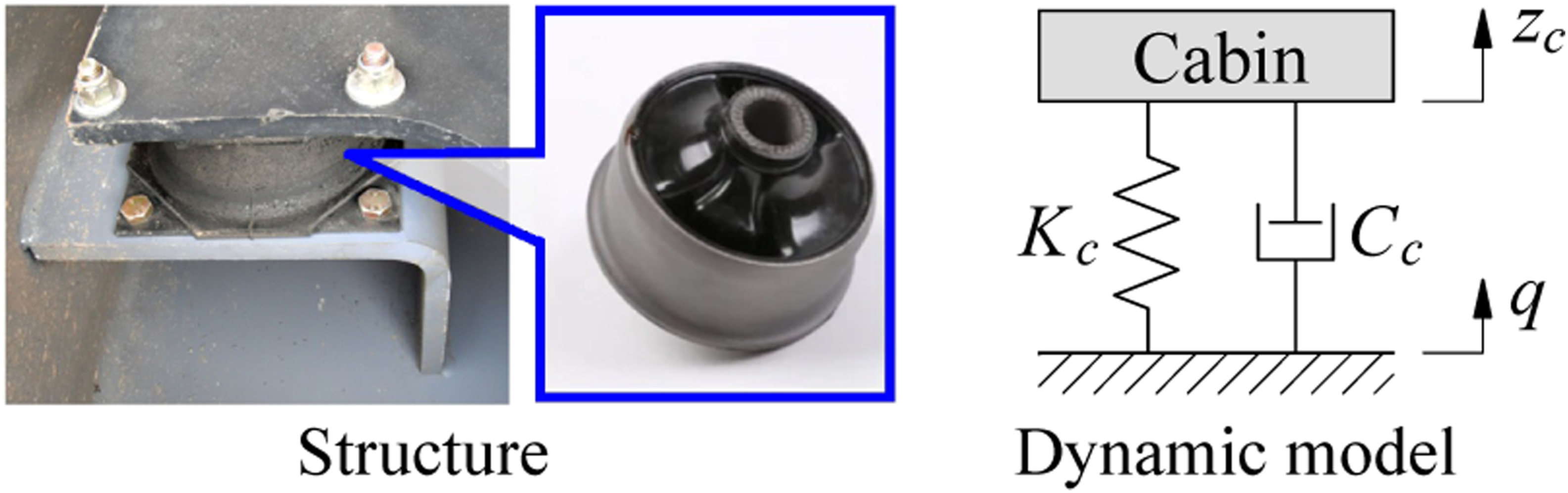
From on the dynamic model of TRIs, the force response (F
cabin
) of cabin’s TRIs has been written as

The isolation performance of the TRIs in Figure 7 was very low under the maximum excitation force F
d
. Thus, the stiffness value of the TRIs needs to be added. In order to solve this issue, a new structure in the cabin’s TRIs using two rubber mounts including the up mount modeled by the stiffness value Kc1 and the down mount modeled by the stiffness value Kc2 was designed for the cabin isolations of the vibratory roller.
6
The model and structure of TRIs using two rubber mounts are depicted in Figure 8. Model of cabin’s improved rubber isolation.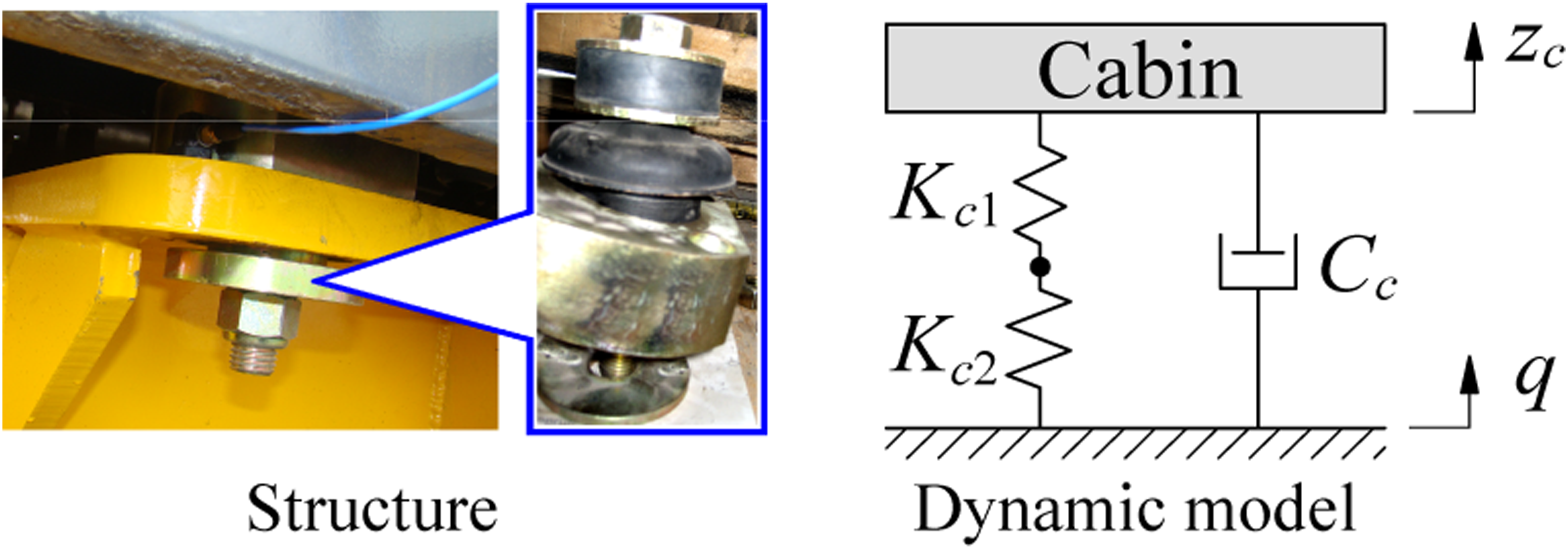
Based on the dynamic model of the TRIs using two rubber mounts, F
cabin
of the cabin’s TRIs is expressed as6

To assess the ride quality and performance of suspension systems in vehicles, the standard of ISO 2631-1: 1997
19
was directly applied in the existing studies of the vehicle’s vibration.7–10 With vibratory rollers, to evaluate vibratory roller’s ride comfort using cabin’s TRIs in Figures 6−8 as well as the isolation performance of the TRIs, according to the ISO 2631-1: 1997, the weighted Root-Mean-Square values of the vertical seat acceleration (RMS
s
), cabin’s pitching acceleration (RMS
φc
), and cabin’s rolling acceleration (RMS
θc
) had been selected as the objective functions. Their RMS values had been written by
RMS accelerations of seat and cabin.
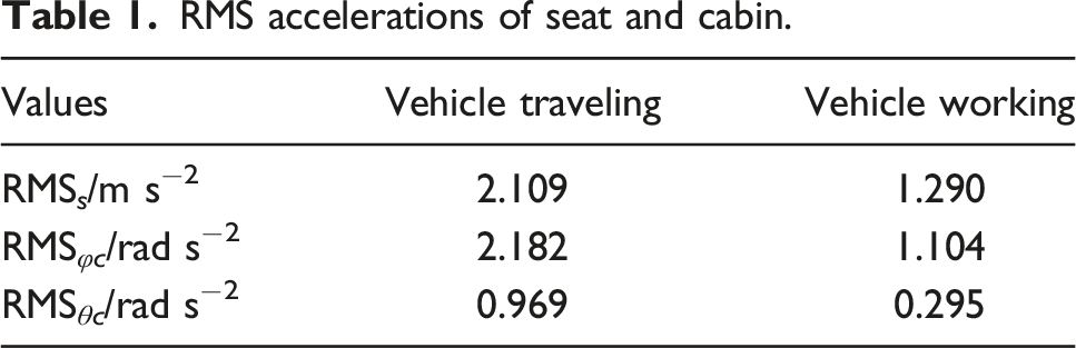
The research results in Table 1 indicated that all values of RMS s , RMS φc , and RMS θc are higher than a w ≤ 0.315 m s−2 of “Not uncomfortable” in ISO 2631-1: 1997. 19 This means that vehicle’s ride comfort is low and the isolation performance of cabin’s TRIs is also low. Especially, the seat acceleration and the cabin’s pitch acceleration are very high. It could be due to the cabin’s TRIs using the rubber material with its characteristics including high stiffness and low damping values.13,17 Consequently, it is difficult to satisfy the vibratory roller’s ride quality by using the cabin’s TRIs.
To reduce cabin shaking and ameliorate seat’s ride comfort of off-road vibratory rollers, a new structure of the cabin’s TRIs using two V-shaped rubber mounts had been designed.6,13 The model and structure of new TRIs have been depicted in Figure 9. Optimal structure of cabin’s TRIs.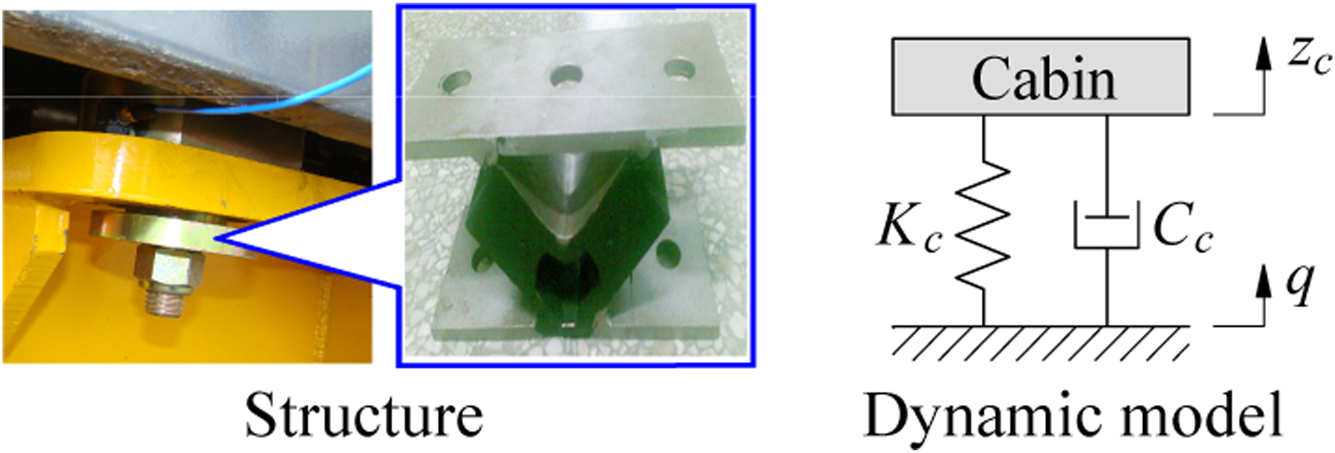
RMS accelerations of seat and cabin with the vibratory roller cab using the new rubber mounts.

Based on three different structures of the cabin’s TRIs in Figures 7−9, the results show that driver’s ride comfort and cabin shaking using TRIs are difficult to be guaranteed based on ISO 2631-1: 1997. Therefore, in order to resolve this issue, the cabin’s new isolations equipped with hydraulic isolations were investigated and developed in the next part.
Cabin’s hydraulic isolations
From the published study results of vibratory roller’s ride quality using the cabin’s TRIs, both seat’s vibration and cabin shaking were very high under vibration excitations in the low-frequency domain.4–7,23,24 Therefore, the cabin’s isolation system should be ameliorated to enhance vibratory roller’s quality.
The existing investigations indicated that hydraulic isolations (HIs) equipped into the engine’s isolation systems improved very good the noise and vibration of engines under low frequencies.16,32,33 From the efficiency of HIs studied and applied in engines, traditional rubber isolations of the cabin in the agricultural machine and earth-moving machinery had been studied and replaced by using the cabin’s HIs for ameliorating ride comfort.14,15,32 In order to outperform ride quality of vibratory rollers, three cabin isolations designed by TRIs,4,6,13 HIs,14,15,33–35 and pneumatic isolations (PIs) 36–38 were applied to vibratory rollers' cabin to assess ride quality isolation efficiency under various conditions of vibratory rollers.8,18,34 Their models and structures have been shown in Figure 10. Different structures and models of cabin isolations. (a) TRIs, (b) HIs, and (c) PIs.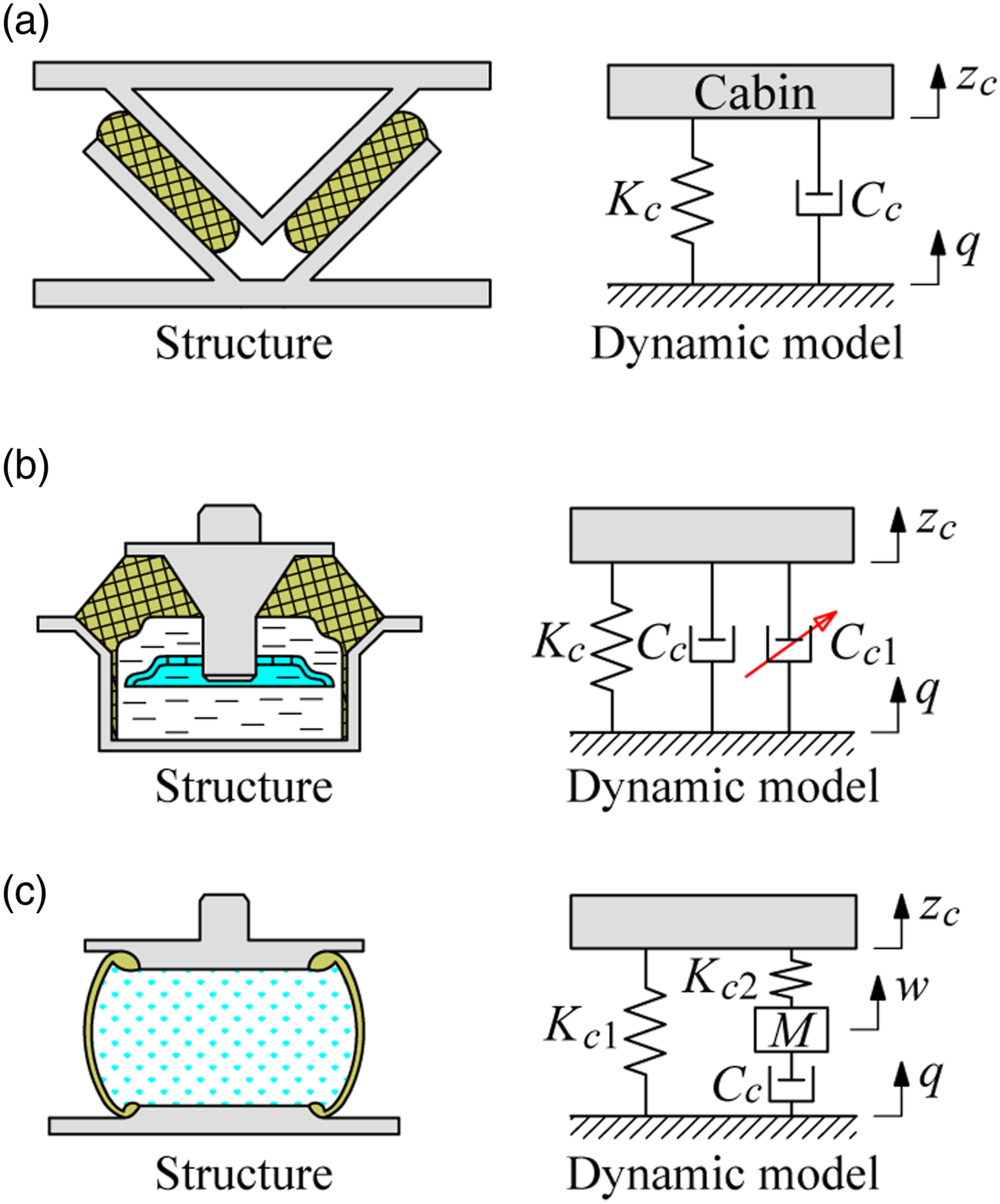
From the mathematical models of TRIs, HIs, and PIs in Refs.4,6,14,36,37, F
cabin
of cabin’s isolation systems is expressed as8,18,34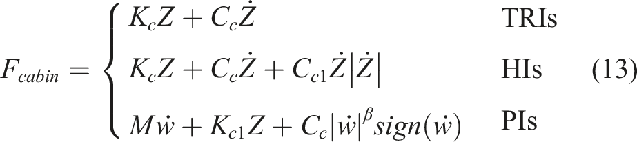
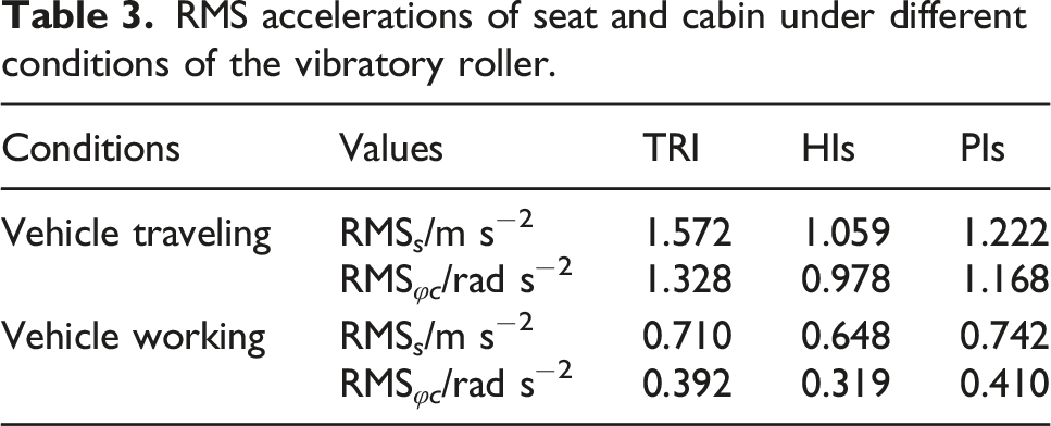
RMS accelerations of seat and cabin under different conditions of the vibratory roller.
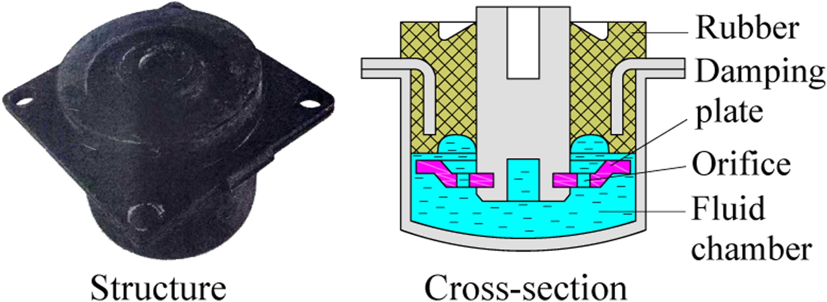
HIs equipped to cabin’s isolation of earth-moving machinery and off-road vibratory roller.
In order to further ameliorate the driver’s ride quality and cabin shaking of vibratory rollers, the nonlinear damping parameter Cc1 in HIs had been controlled in the next part.
Cabin’s semiactive isolations
n order to augment the HIs performance, based on the development of science and technology, the control method of the PID combined with Fuzzy logic controls had been researched to control the magnetorheological damping (MRD) force of semiactive HIs in engines.
28
This semiactive HIs was then used in vehicle’s isolation systems to augment ride quality.28,39,40 The models and structures of the engine’s passive HIs and semiactive HIs are shown in Figure 12. The engine’s HIs. (a) passive HIs and (b) semiactive HIs.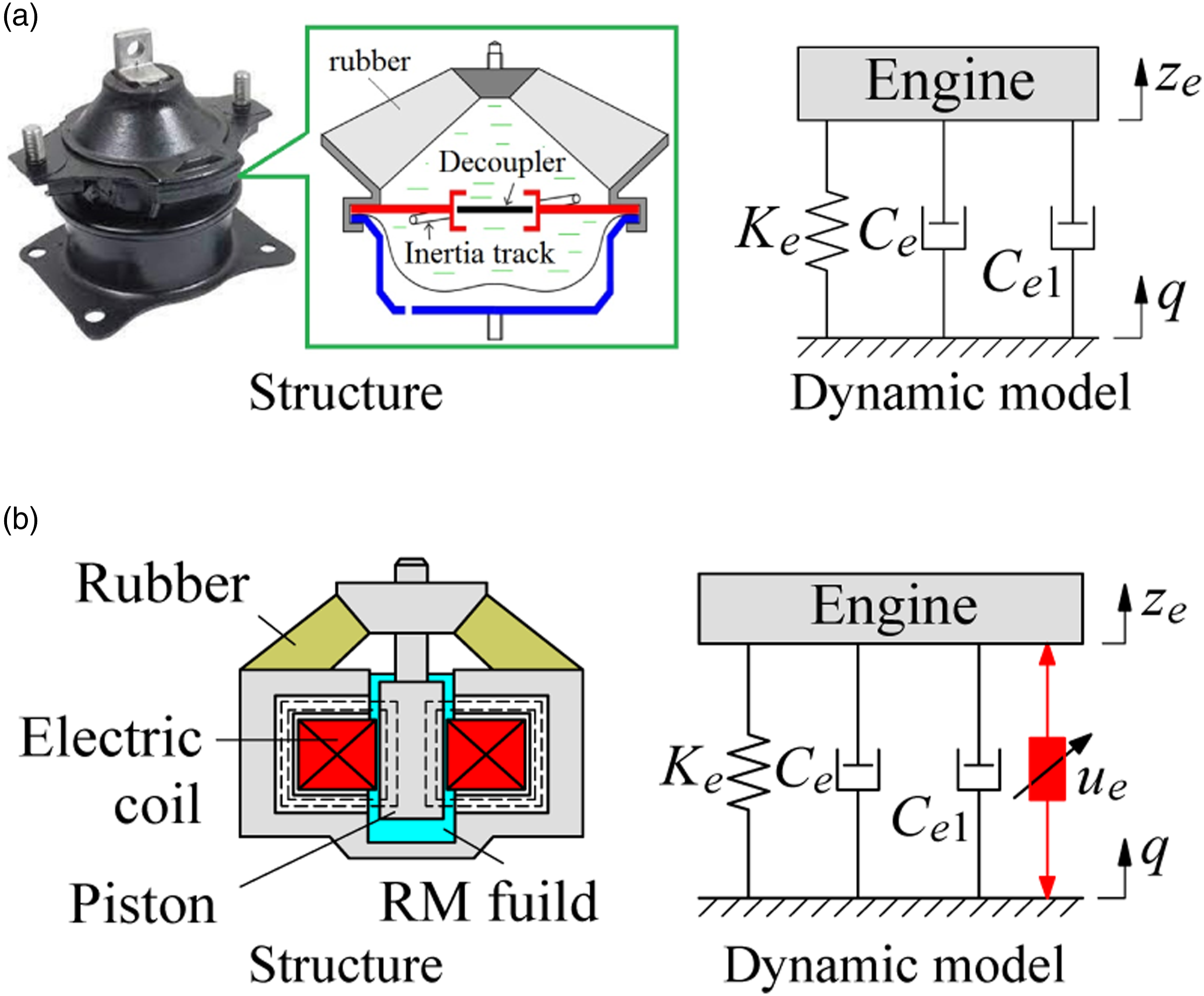
Based on the model of the passive and active HIs, F
engine
of the engine’s HIs has been written as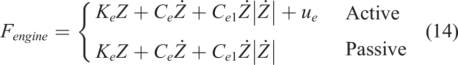
Based on MRD’s control force in vehicle’s semiactive HIs and engine’s semiactive HIs,39,40 this semiactive HIs was also investigated and used on the cabin’s isolation system of off-road vibratory rollers to ameliorate ride quality and reduce cabin shaking.8,17,18,34 The model and structure of cabin’s semiactive HIs are depicted in Figure 13. Cabin’s isolation system is equipped with HIs and semiactive HIs.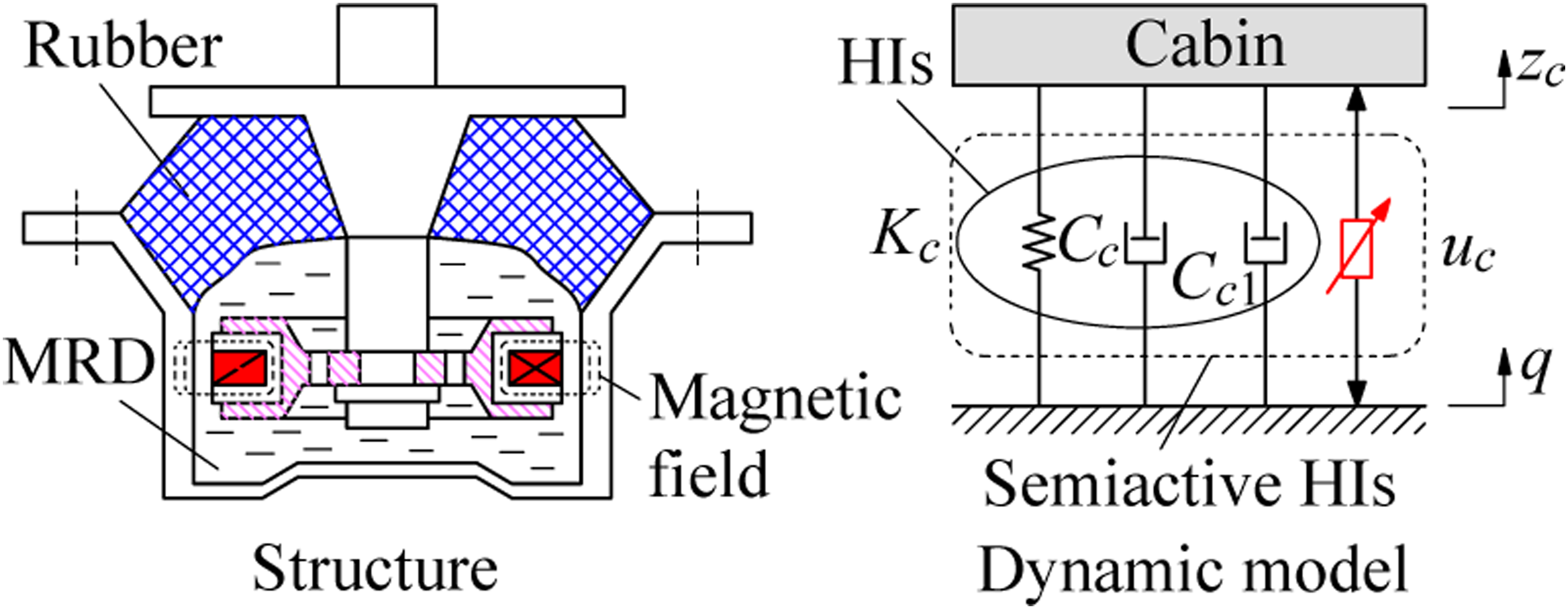
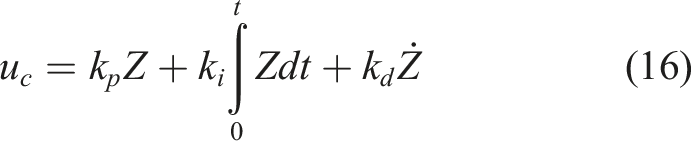
Where u c is the control force of the semiactive HIs.
The force response F
cabin
of the cabin’s semiactive HIs has been described as8,17,18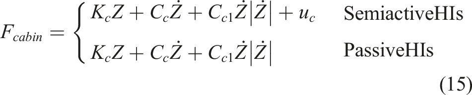
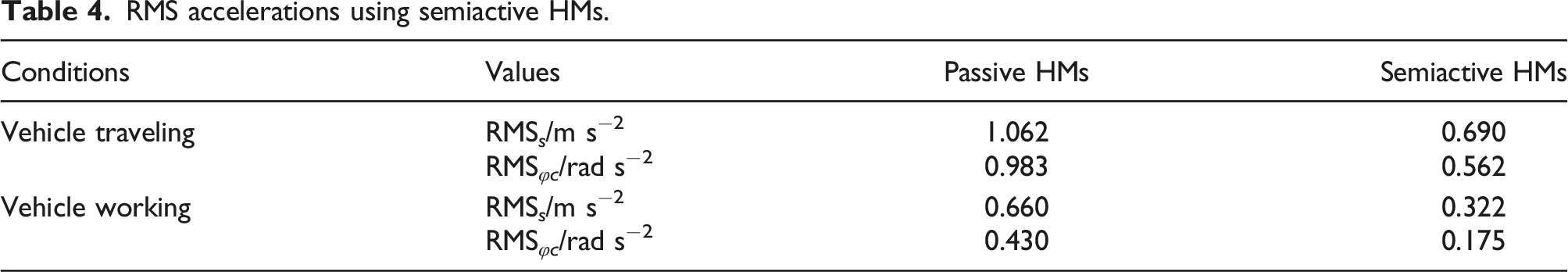
RMS accelerations using semiactive HMs.
In order to solve this problem, from the obtained results of the isolation efficiency of PIs in low-frequencies and isolation efficiency of HIs with its high damping value,15,34,41 both PIs and HIs (PHIs) were then combined for the cabin’s semiactive suspensions of the agricultural tractors to ameliorate the ride comfort.
42
The PHIs is also studied and used on cabin isolation of vibratory rollers to ameliorate ride comfort.18,39,42 The structure and control model of the cabin’s semiactive PHIs have been shown in Figure 14. Model of the cabin isolation using HIs combined with PIs.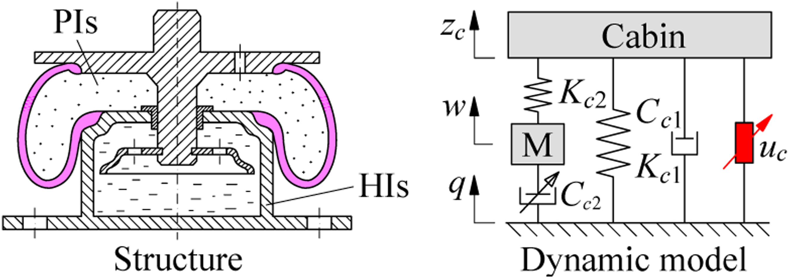
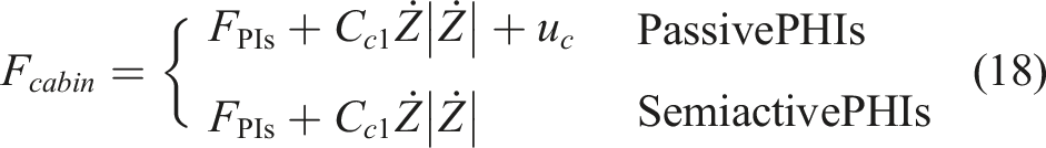
The F
cabin
of the cabin’s semiactive PHIs is written as
RMS accelerations of seat and cabin when the vehicle is working.
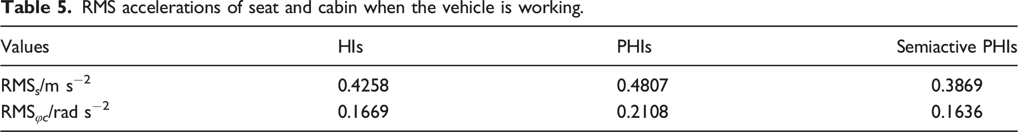
The numerical simulation result of the RMS s and RMS φc with the cabin’s PHIs is slightly augmented in comparison with the cabin’s HIs. However, with the cabin’s semiactive PHIs controlled, both RMSs and RMSφc are remarkably decreased compared to both cabin’s HIs and PHIs. Especially, RMS φc = 0.1636 rad s−2 is smaller than a w = 0.315 rad s−2 in ISO 2631-1: 1997, 19 this means that the cabin shaking is good. But the obtained value of RMS s with cabin’s semiactive PHIs in Table 5 is bigger than a w ≤ 0.315 m s−2, 19 therefore, the off-road vibratory roller’s ride quality is still low. In addition, the studies of PHIs or semiactive PHIs indicated that the structures in both PHIs and semiactive PHIs were complicated; their cost was also very high. This implied that it's not easy for the application of semiactive PHIs in vibratory rollers' cabin to reach driver’s ride quality. Therefore, to reduce the seat’s vibration in vibratory rollers, the seat suspension has been continuously investigated and developed in the next part.
The research process of seat suspensions
Development of seat’s traditional suspensions
In the design process of the seat suspension system in vehicles, its structure was designed by the traditional seat suspension (TSS) including the spring and damper with their constant stiffness and damping parameters.4,6,7,42 Its mathematical model has been illustrated in Figure 15a. Structure and model of various suspension systems used for the seat: (a) TSS, (b) air suspension, and (c) active suspension.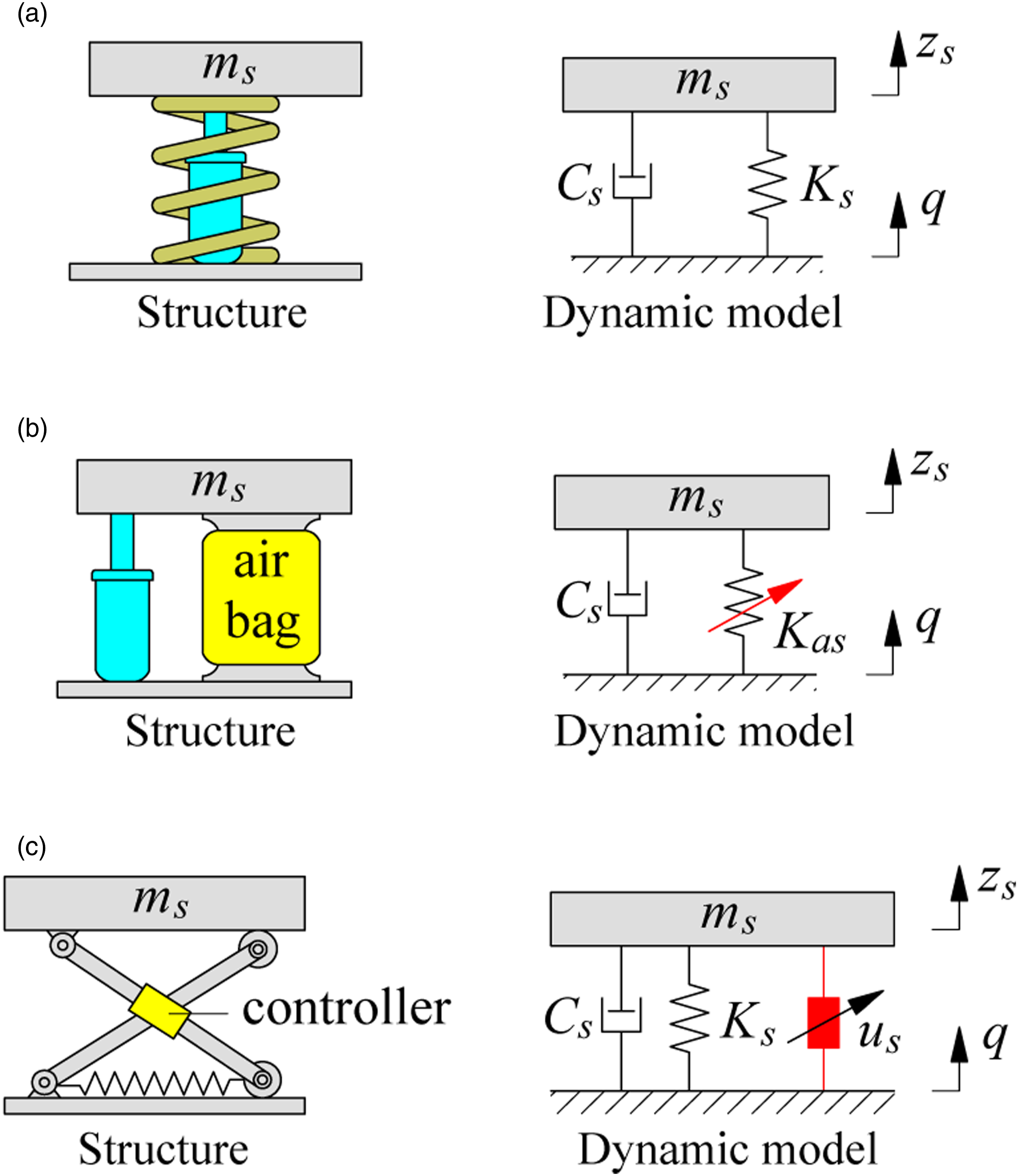
With the structure of TSS, its advantage is simple in the design process. However, the efficiency of TSS in improving vehicle’s ride comfort is low, especially in the low-frequency region. Therefore, with the high isolation efficiency of air-springs researched under low-frequency excitations,36–38 the seat suspension equipped with the air spring was then applied to augment ride quality.38,41,43–45 In order to ameliorate the efficiency of the air suspension, its operation parameters were then optimized or controlled.38,41,43–47 Its control model and structure have been shown in Figure 15b. Besides, based on the MRD controlled and applied on the vehicle semiactive suspension systems, 9,39,40,48,49 the seat’s TSS using the active damping force was then researched and applied on the seat suspension system of heavy trucks, off-road vehicles, and vibratory rollers to augment driver’s ride quality.38,41,43–45,49–51 Its structure and control model is shown in Figure 15c.
Where K s is the stiffness parameter of the TSS, C s is the damping parameter of the TSS, K as is the nonlinear stiffness parameter of the air spring, and u s is the active control force of the semiactive TSS.
The F
seat
of seat’s semiactive HIs has been described as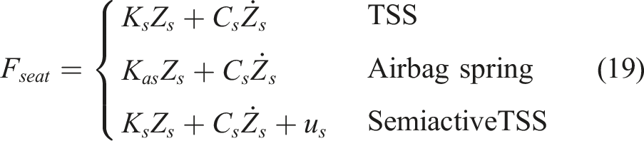
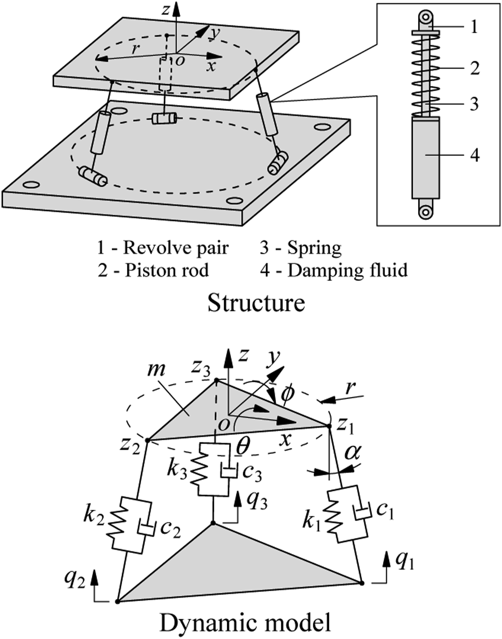
Besides, a parallel seat suspension using three pairs of springs and dampers was also proposed for off-road vehicles' seat to augment driver’s ride quality.
52
Its structure and dynamic model are illustrated in Figure 16. F
seat
of the parallel seat suspension is expressed as Structure and model of the parallel seat suspension.
Although the above studies mainly assessed the isolation efficiency of the seat suspension based on different vehicle models and different simulation conditions. No specific studies are comparing the isolation efficiency between seat suspension models. However, all the above studies have the same conclusion that using the controlled seat suspension ameliorates ride comfort of the driver better than other suspension systems.46,47,49,50,51 With vibratory rollers, the use of the seat’s semiactive suspension may increase the vibratory roller’s costs, which may affect commercial competition. Accordingly, in practice, the vibrating roller was mainly equipped with the TSS.4,6,7,8,9,15,16,17,18 The vehicle’s ride comfort was mainly enhanced by improving cabin’s isolation systems. However, the isolation efficiency of TSS in vibratory rollers was very low.6,7,42 In addition, the isolation efficiency of the cabin’s semiactive HIs and PHIs in enhancing vehicle’s ride quality was also limited.8,17,18,34,42 Thereby, with the high isolation efficiency of quasi-zero-stiffness elements (QSE) investigated and applied to vehicles' seat suspension for improving ride comfort, QSE was also researched for the vibratory roller seat to ameliorate ride comfort. The structure and characteristics of QSE have been presented in the next part.
Quasi-zero stiffness elements
The term and structure of QSE were defined as follows21,22,48,53: With a structure designed by an elastic spring element; when the compression force F is increased then the deformation z of the elastic spring is also increased and vice versa (F = Kz). In this case, K has been defined by the Positive-Stiffness-Element (PSE) in QSE’s structure, as plotted in Figure 17 of PSE. On the contrary, with a structure designed by two symmetrical-elastic elements of the spring or bar, when the compression force F is increased then the deformation z of the elastic springs or bars is reduced and vice versa. In this case, K has been defined by the Negative-Stiffness-Elements (NSE) in QSE’s structure, as plotted in Figure 17 of NSE. The structure and characteristics of the QSE.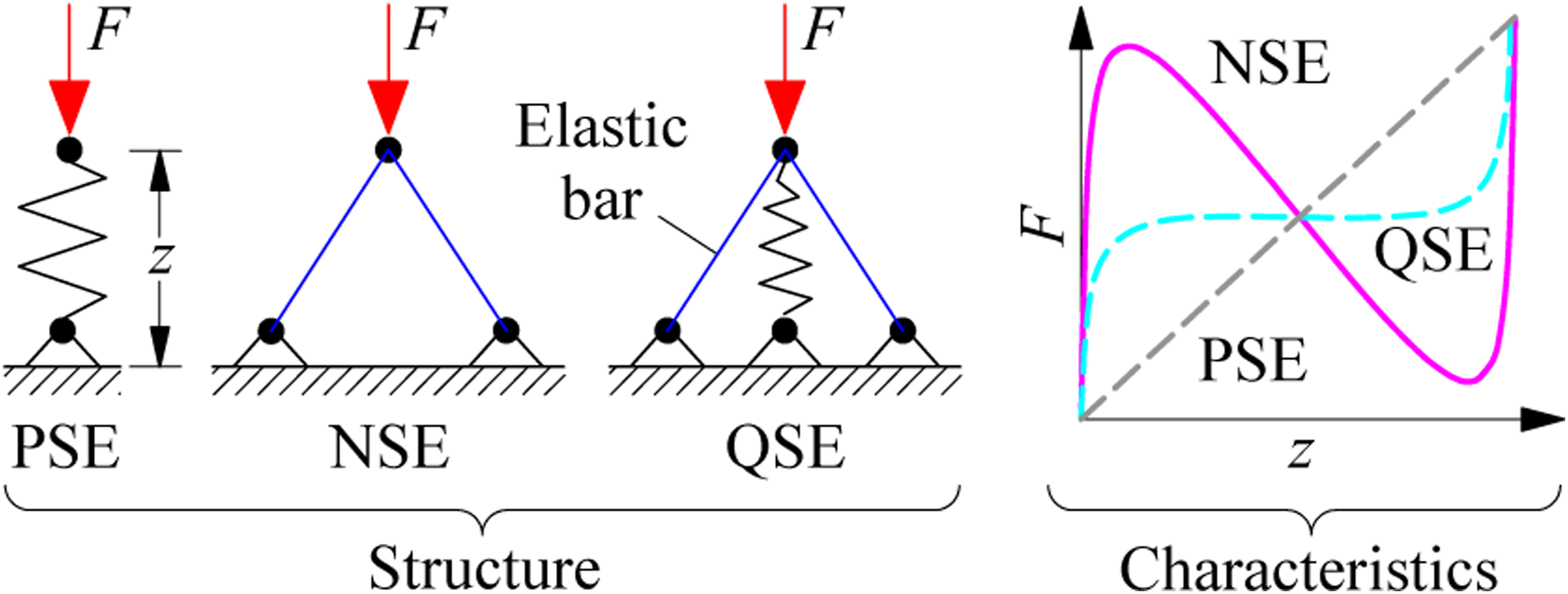
With a new structure designed by PSE combined with NSE, when the deformation z of the structure is increased or reduced, the compression force F does not change and is approximately zero. In this case, K has been defined by the Quasi-zero-Stiffness-Elements (QSE) in QSE’s structure, as plotted in Figure 17 of QSE. From the characteristics and simple structure of QSE, the structure of QSE was then developed and used on the seat suspension system to ameliorate ride quality of vehicles in the next part.
Development of seat suspension using QSE
The QSE added to the seat suspension was built by two horizontal and symmetrical elastic springs. One end of the elastic spring was fixed to the wall and another end was connected to the seat via the sliding guide block and hard bar with a length of c.20,21,22,54 QSE’s model and structure have been illustrated in Figure 18. Structure of seat suspension using QSE.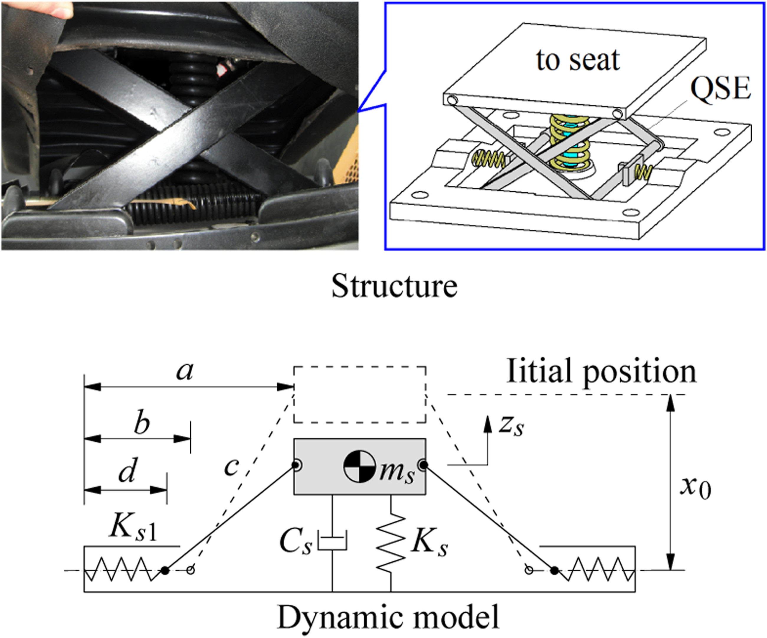
Where m s and z s are the seat’s mass and displacement, x0 is the initial position of the seat, a is the distance from the seat to the wall, b is the initial length of elastic springs, d is the length after deformation of elastic springs of QSE, Ks1 is the stiffness parameter of QSE, K s and C s are the stiffness parameter and damping parameter of TSS, respectively.
From QSE’s dynamic model depicted in Figure 18, Fseat of the seat suspension using QSE was then calculated as20,22
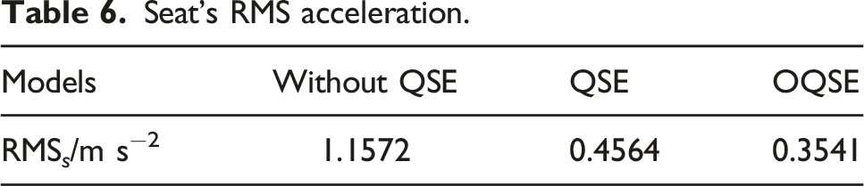
From the obtained results of the seat suspension embedded by QSE or optimized QSE (OQSE),20,21 the values of RMS
s
and the Power-Spectral-Density (PSD) acceleration of the seat have been plotted in Figure 19. Seat isolation using QSE. (a) acceleration and (b) PSD value of the seat’s acceleration.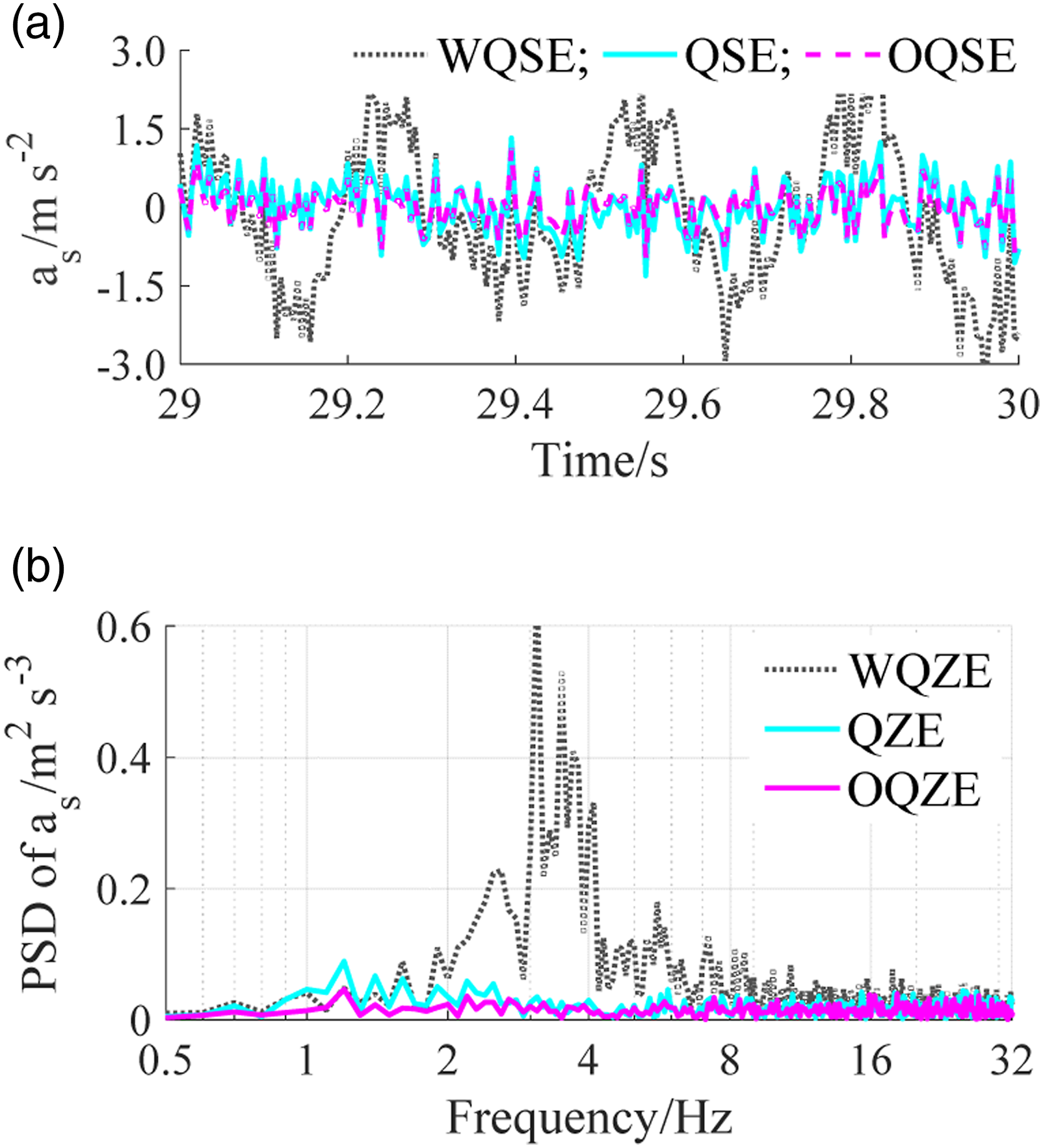
Seat’s RMS acceleration.
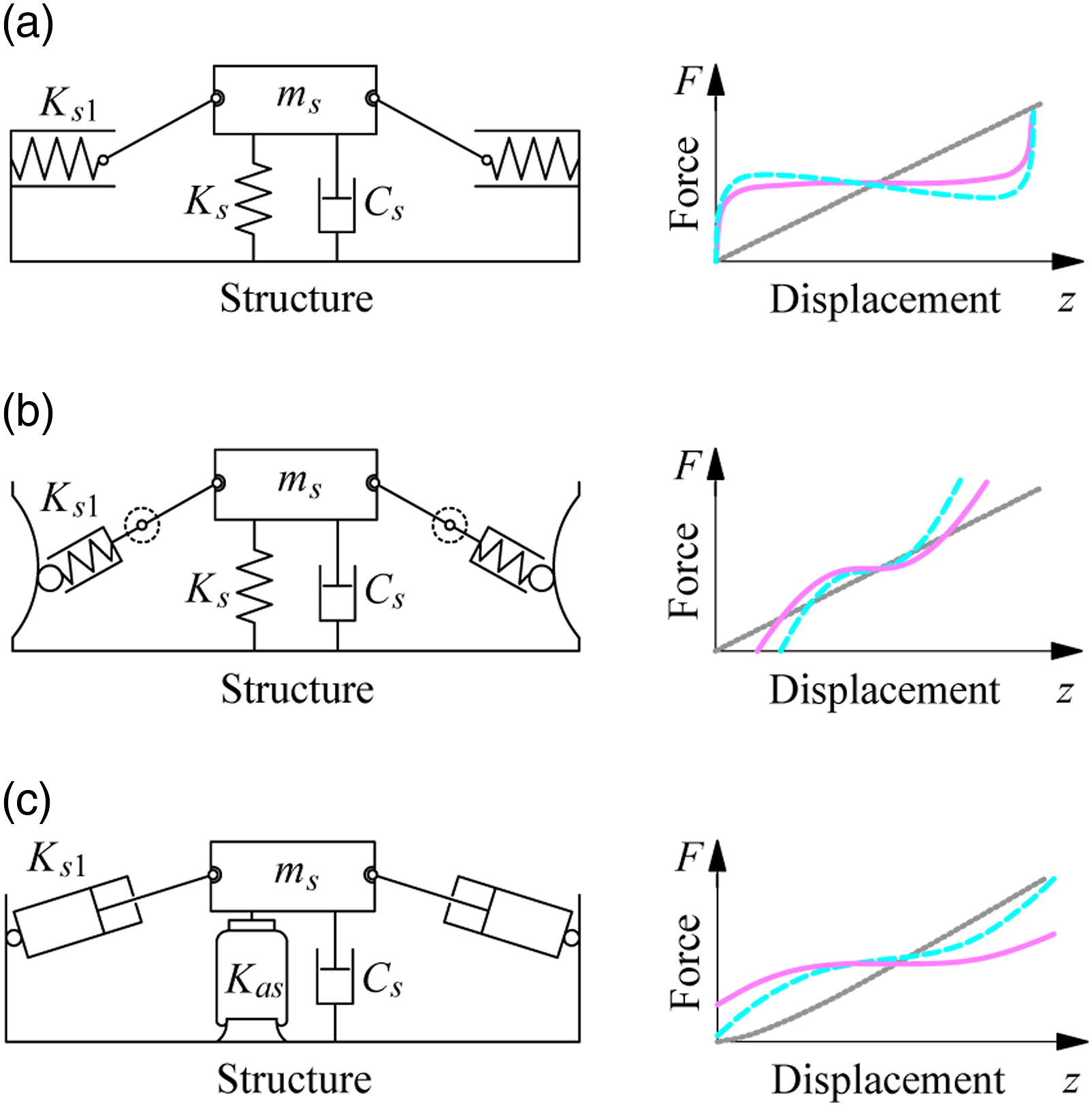
The structure and force-displacement characteristics of (a) QSE-SS, (b) QSE-RS, and (c) QSE-AS embedded in the suspension system of the seat.
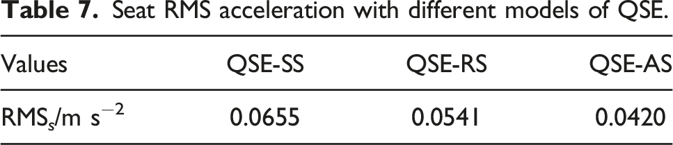
Seat RMS acceleration with different models of QSE.
In addition, based on the structure of QSE-SS (or QSE-1) designed by two horizontal springs in Figures 18 and 20a, and 21 with QSE-1, three various structures of QSE-2, QSE-3, and QSE-4 were proposed and studied for ameliorating the ride comfort of the driver,58–60 as shown in the same Figure 21. Their dynamic parameters were also optimized to compare the isolation efficiency of QSE-1, QSE-2, QSE-3, and QSE-4.
60
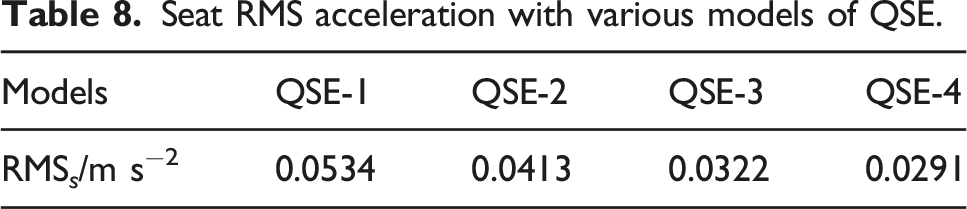
Their RMS
s
value is provided in Table 8.
60
Studies indicated that the structure of QSE-4 improved the ride comfort better than that of other structures. However, the efficiency between the QSE-4 and QSE-AS has not been compared yet. QSE’s various structures use steel springs embedded in the suspension system of the seat. Seat RMS acceleration with various models of QSE.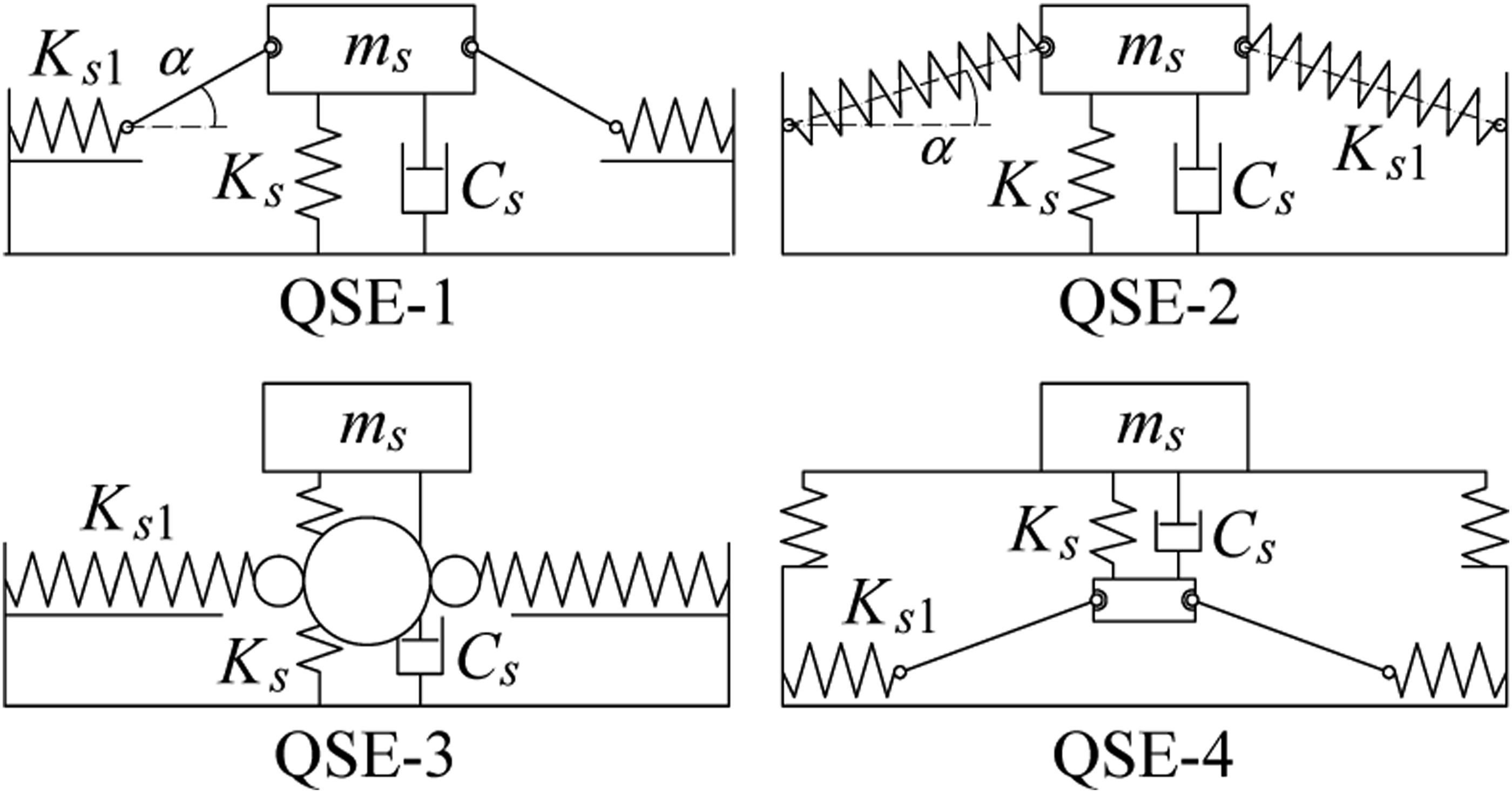
The QSE’s experiment added into the seat suspension had been done in Refs.45,49,61 The result revealed that the riding comfort had been strongly ameliorated by QSE designed into the seat suspension. But the existing investigations also indicated that the noise level of the seat suspension using the QSE designed by the elastic springs is significantly increased. In order to solve this issue, the elastic springs of QSE replaced by using magnetic springs (QSE-MS) were investigated and developed in Refs.62–65 Its mathematical model and structure have been exhibited in Figure 22.62,63 QSE’s structure using the magnetic spring.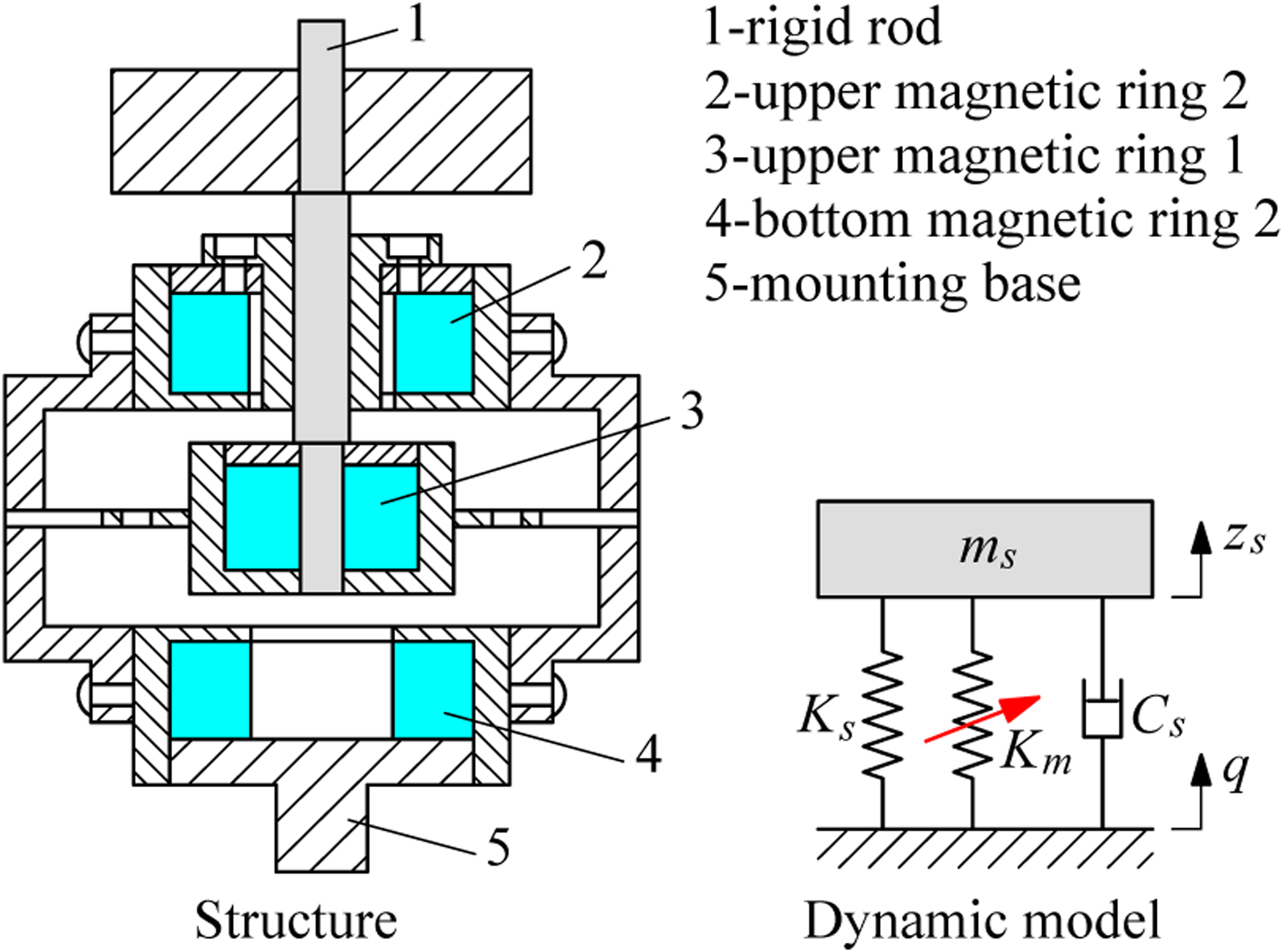
Where K m is the magnetic negative stiffness of the model.
The above research indicated that the QSE added into the seat’s suspension was very effective in enhancing the riding comfort of vehicles.18,20,22,54,57–60,62–65 Therefore, QSE was also developed for vibratory roller seat to augment driver’s riding comfort in the next part.
Vibratory roller’s seat suspension using QSE
In the existing research of vibratory rollers, 4,6–10,12,17,18 cabin’s semiactive HIs or semiactive PHIs could control the cabin shaking and reduce the seat vibration. However, the seat’s acceleration was high based on ISO 2631-1: 1997.
19
Therefore, the seat’s suspension added by OQSE and the cabin’s isolation system equipped with HIs of vibratory rollers was studied in Ref.7,9,56,58. The vehicle’s structure with seat’s OQSE and cabin’s HIs has been plotted in Figure 23. Modelling of the vibratory roller equipped with HIs of the cabin and OQSE of the seat.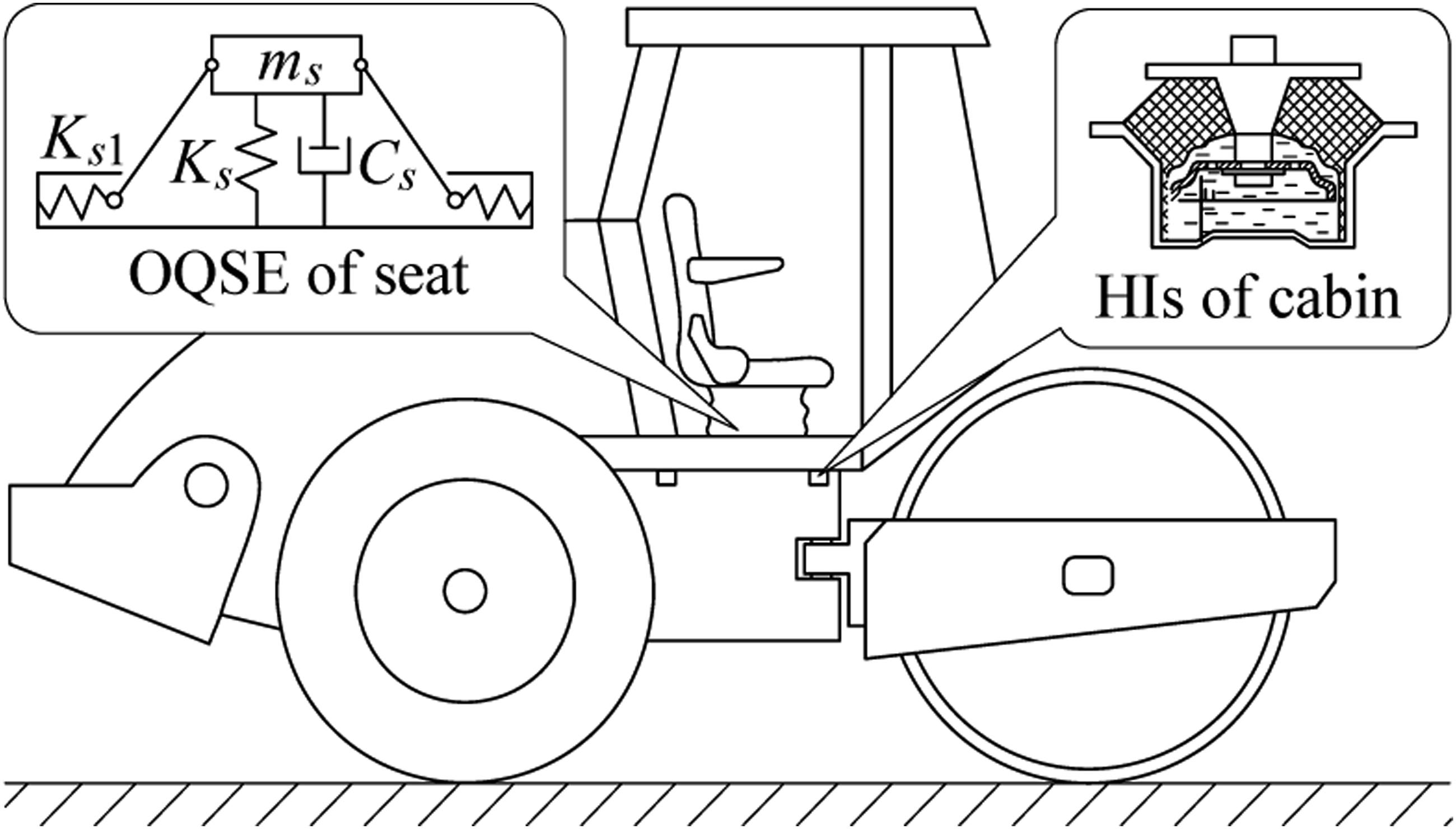
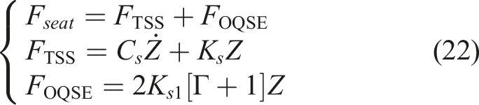
The F
seat
of the seat suspension added by OQSE has been described as
56
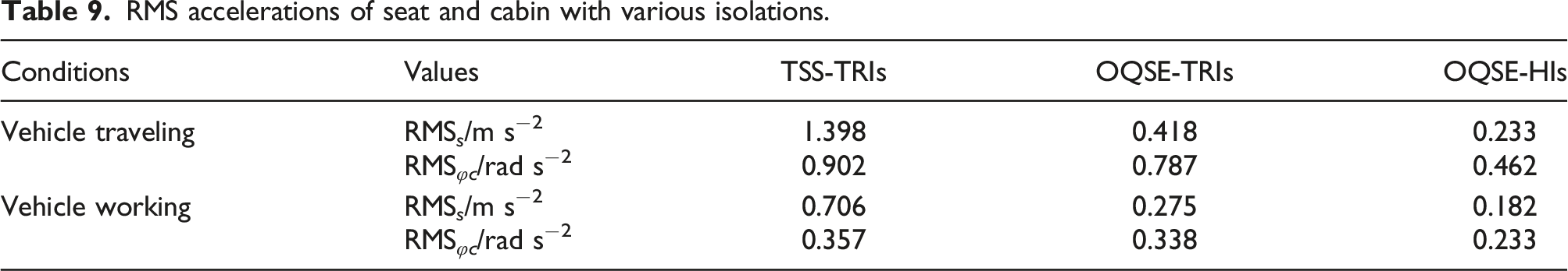
RMS accelerations of seat and cabin with various isolations.
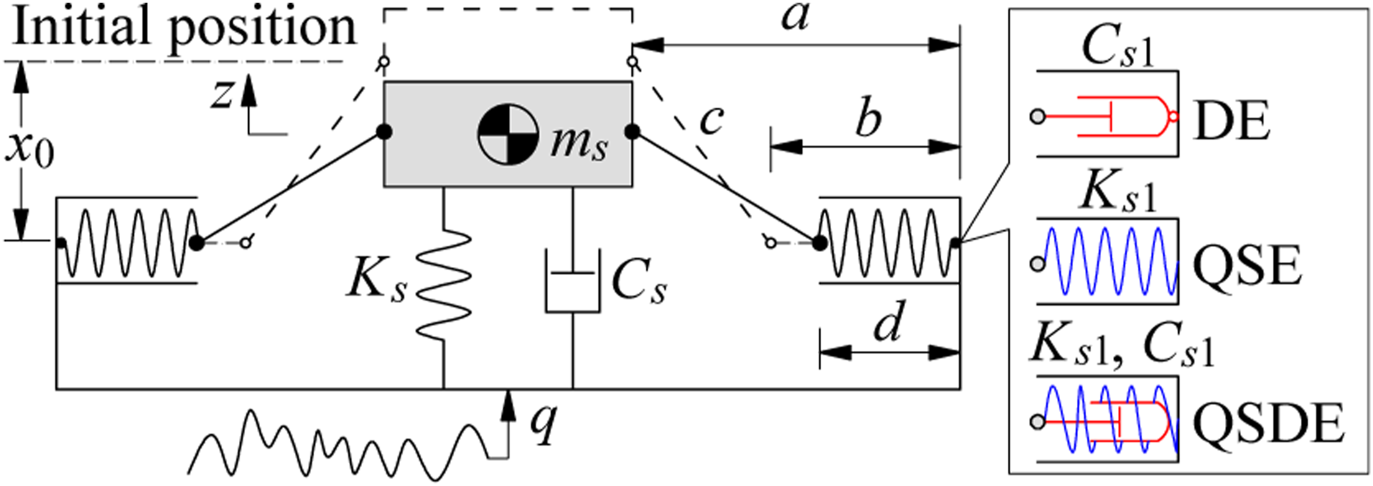
Modelling of vibratory roller’s seat suspension using different structures of DE, QSE, and QSDE.
The F
seat
of the seat suspension supported by QSE, DE, and QSDE has been described as
55

Seat RMS acceleration when the vehicle is working.

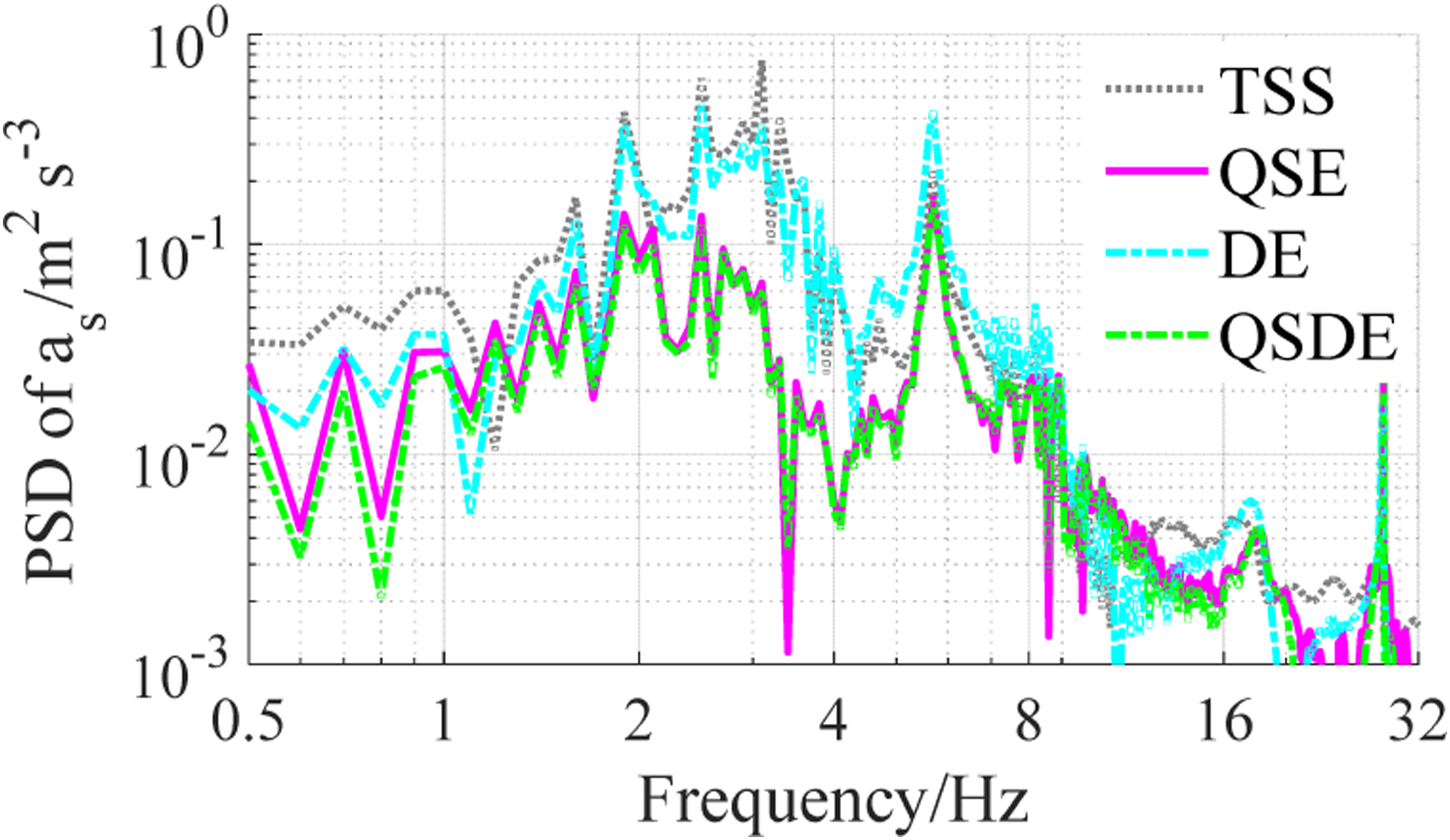
The PSD acceleration response of the seat under the working condition of the vehicle.
The research result also shows that both RMS
s
and PSD of the seat using QSE were improved better than that of TSS and DE. Besides, the vibratory roller’s experiment with QSE added into seat’s TSS and HIs used in cabin isolation was also performed in Refs.48,61. The experimental results of both acceleration response and PSD acceleration response of the seat have been plotted in Figures 26(a)−(b).
48
From the investigation results of vibratory rollers with the seat’s TSS embedded by QSE and cabin isolation using the HIs in the above studies, we can see that the vibratory roller’s riding quality and cabin shaking can be solved. Simulation and experiment results of the vehicle equipped with QSE of the seat and HIs of the cabin. (a) acceleration and (b) PSD value of seat acceleration.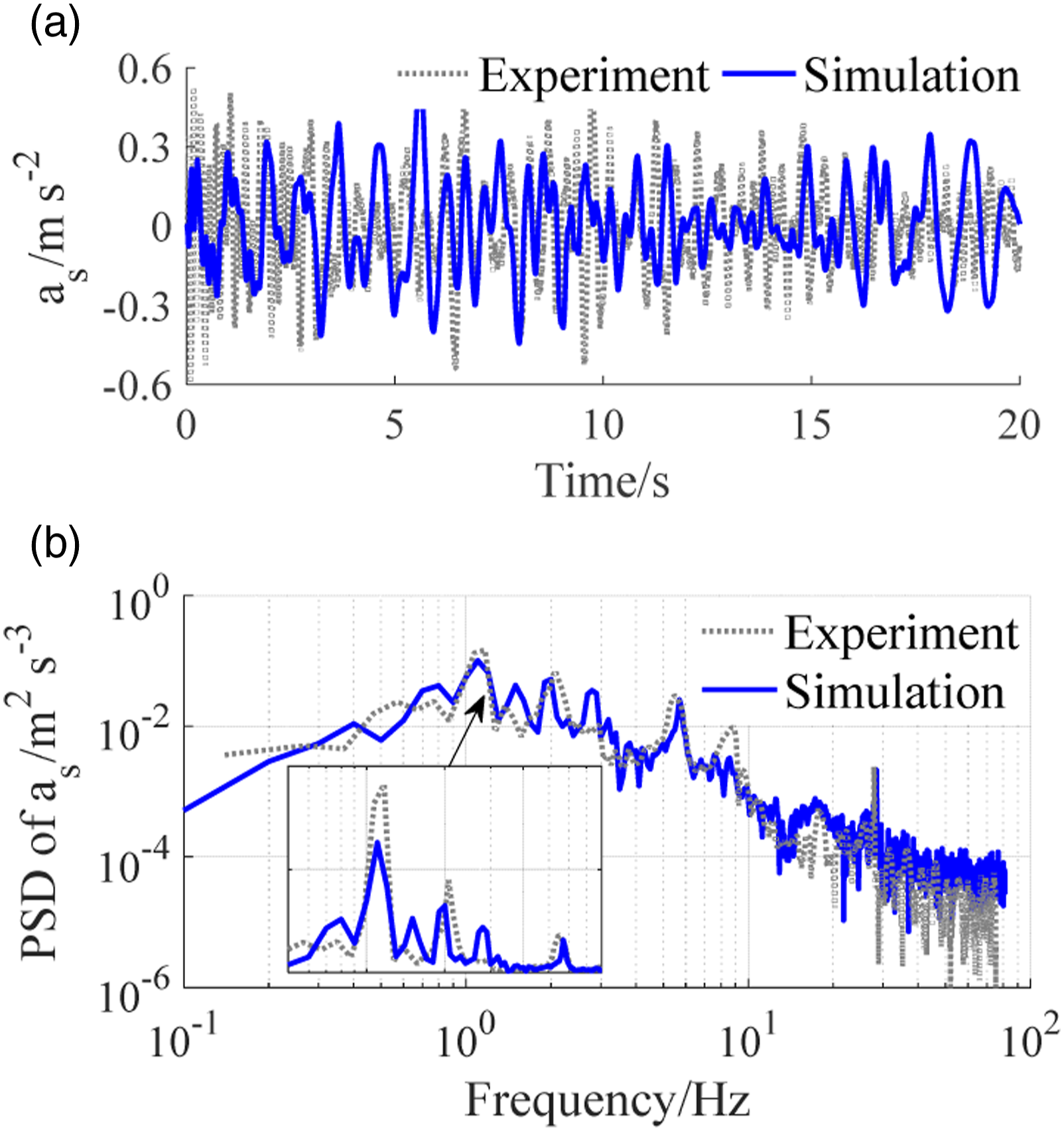
RMS accelerations of seat and cabin using various isolations under an excitation 28 Hz in the vibratory drum.
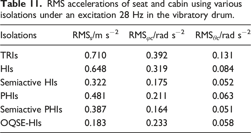
The result in Table 11 indicated that both values of RMS φc and RMS θc of the cabin using the semiactive PHIs were lower than other isolation systems. However, the cabin’s isolation structure equipped with semiactive PHIs is complex. This could increase the manufacturing cost of vibratory rollers. Therefore, the application of the semiactive PHIs to the vibratory roller cabin’s isolation systems is difficult. On the contrary, with simple structure and high isolation efficiency of HIs and QSE researched and applied to the vibratory roller cabin and seat,7,20,21,53,55,56 The result in the same Table 11 with OQSE-HIs indicated all values of RMS s , RMS φc , and RMS θc of the seat and cabin are smaller than that of other isolations of vibratory roller's cabin and seat. Consequently, both QSE added into the seat suspension and cabin isolation used by HIs of off-road vibratory rollers are investigating and developing.
Conclusions
With the vibratory roller cabin’s isolation systems: In order to ameliorate the vehicle’s riding quality, the isolation efficiency of the cabin isolations has been always studied and developed based on the change of the structure as well as the dynamic model of the cabin isolations. Firstly, the cabin isolations using the TRIs were applied to the vibratory roller, then, the HIs and semiactive HIs had been used to replace the cabin’s TRIs. Finally, the PHIs and semiactive PHIs are studied and developed to augment the riding quality of the driver and mitigate cabin shaking. However, the vibratory roller’s riding quality is still low based on ISO 2631-1:1997. Thereby, the seat suspension system is continuously investigated and developed.
With the seat suspension system: In order to enhance the riding quality, the traditional seat suspension of vibratory rollers had been added by the QSE. The optimized parameters of the QSE as well as the different structures of the QSE were researched to evaluate the stability and efficiency of the QSE. Besides, the experimental study of the QSE added into the seat suspension of vibratory rollers had been done to assess the QSE’s actual efficiency. The obtained acceleration of the seat was smaller than a w = 0.315 m s−2 in ISO 2631-1: 1997. However, the cabin pitching angle using the HIs is still high.
Consequently, in order to ensure both the driver’s riding quality and reduce cabin shaking of vibratory rollers, the cabin’s isolation systems need to be equipped with the semiactive HIs or semiactive PHIs whereas the seat’s suspension needs to be embedded by the QSE optimized. This problem should be continuously studied and developed in the next works.
Footnotes
Declaration of conflicting interests
The author(s) declared no potential conflicts of interest with respect to the research, authorship, and/or publication of this article.
Funding
The author(s) received no financial support for the research, authorship, and/or publication of this article.