
Abstract
To address the vibration problems caused by dual-input power confluence and planetary-stage power splitting in helicopter main reducers, a dual-input parallel-shaft planetary gear transmission system is investigated. A bending–torsional coupled dynamic model is established by considering gear-pair and spline-pair mesh stiffness, equivalent error, backlash, support stiffness, and spline shaft torsional stiffness. The time-varying mesh stiffness of gear pairs is calculated using the potential energy method and verified by finite element analysis. The effects of key excitation parameters, input speeds, and load conditions on the system vibration responses are analyzed. The results show that increasing gear-pair mesh stiffness generally reduces the torsional vibration responses of rotating components, while equivalent errors significantly amplify system torsional vibration. The spline shaft torsional stiffness affects vibration transmission between the parallel-shaft and planetary gear stages. The results provide a theoretical basis for error control, spline connection stiffness matching, and low-vibration optimization design of helicopter gear transmission systems.
Keywords
Introduction
It is essential to develop a gear transmission system with better transmission performance by constructing a dynamic model that can simulate the actual working conditions of the system and by clarifying the effects of various excitation factors on the vibration response. At present, scholars have conducted extensive and in-depth research on the vibration characteristics of gear transmission systems.
In 2008, Stringer 1 proposed a method to predict the vibration characteristics of the gear system of the helicopter main reducer. Based on the established six-degree-of-freedom gear rotor dynamic model considering the gyro matrix, the vibration response of the system was analyzed and predicted. In 2010, Inalpolat et al. 2 analyzed the influence of internal excitation parameters and working conditions such as time-varying mesh stiffness, gear manufacturing error, and input speed on the dynamic response of the multi-stage planet gear system. The research conclusions were verified using an automatic gearbox test-bed. In 2020, Xiao et al. 3 established a dynamic model of the planet gear system considering crack faults based on the lumped parameter method. The vibration characteristics of the gear system in the normal state and the crack-fault state were compared. The influence of the crack faults on the dynamic response of the gear was analyzed by a bench test. In 2021, Minda et al. 4 studied the influence of nonlinear factors, such as backlash, on the nonlinear vibration response of the planet gear transmission system using phase-plane diagrams and FFT spectra. In 2020, Tatar et al. 5 used a three-dimensional dynamic model to study the influence of parameters on the dynamic response of a planet gear-rotor system, including the number of planet gears, the mass of planet gears, the mesh stiffness of gears, and the speed of planet gears. It was found that these parameters have different effects on natural frequencies and vibration modes, and the mass and mesh stiffness of planet gears have significant effects on the overall dynamic response. In 2024, Zhang et al. 6 considered the thermal-fluid-solid coupling effect of helical gear transmission and established a dynamic model considering temperature, lubrication, mesh stiffness, transmission error, and other factors using the lumped parameter method. Based on vibration and acoustic experiments, the accuracy of the model was verified. In the same year, Li et al. 7 established a multi-degree-of-freedom helical gear-rotor-bearing coupling dynamic model of a wind turbine gearbox using the lumped parameter method. The influence of internal and external excitation changes on the amplitude of the directional vibration response of gears was studied. This provided theoretical support for the optimal design and fault diagnosis of wind turbine gearboxes. In 2024, Liu 8 studied the dynamic characteristics of the multi-stage planet gear system under crack-fault conditions. The effects of load torque and mesh damping on its vibration characteristics were revealed. A calculation method for the mesh stiffness of cracked gears based on the improved potential energy method was proposed. It provided theoretical support for vibration control and dynamic optimization of gear systems with crack faults. In 2024, Pizzolante et al. 9 combined the Asymptotic Numerical Method with the Harmonic Balance Method to analyze the nonlinear dynamics of spur gears with time-varying mesh stiffness and backlash. The results showed that the method can efficiently capture periodic responses and nonlinear solution branches of gear systems. In 2025, Hu et al. 10 established a coupled dynamic model of a helicopter main reducer including a bevel gear set, a planetary gear set and a connecting shaft. The influence of coupling effects and sun gear tooth crack on the vibration characteristics of the main reducer was analyzed and experimentally verified. In 2026, Gao et al. 11 built a 36-degree-of-freedom nonlinear dynamic model of a non-circular planetary gear train under time-varying parameter excitation. The effects of excitation frequency, error amplitude, meshing damping ratio and output torque on bifurcation, chaos and dynamic load characteristics were revealed. In 2025, Lian et al. 12 established a translational-torsional dynamic model of a planetary gear system considering motor torque ripple, time-varying mesh stiffness and backlash. The coupling mechanism between motor torque ripple and gear vibration response was revealed, and a torque ripple suppression strategy was proposed. In 2026, Bi et al. 13 developed a 36-degree-of-freedom bending-torsional coupling nonlinear dynamic model for 4–6 order non-circular planetary gear systems. The effects of rotational speed, eccentricity, damping and backlash on nonlinear vibration responses were analyzed and verified by experiments.
Although existing studies have extensively investigated the effects of time-varying mesh stiffness, transmission error, backlash, damping and support stiffness on the vibration characteristics of gear transmission systems, the vibration response of coupled systems composed of dual-input parallel-shaft transmission and planetary gear transmission remains insufficiently explored. Under the combined effects of intermediate spline-shaft connection, dual-input power confluence and planetary-stage power splitting, such systems involve more excitation sources and more complex transmission paths, resulting in more pronounced vibration sensitivity and phase coupling among different components. Therefore, studying the vibration response characteristics of such systems under different operating conditions is of great significance for vibration and noise control, condition monitoring,14,15lightweight design16,17 and transmission performance optimization.18,19
Calculation of dynamic incentive parameters for the system
Construction of the System’s three-dimensional physical model
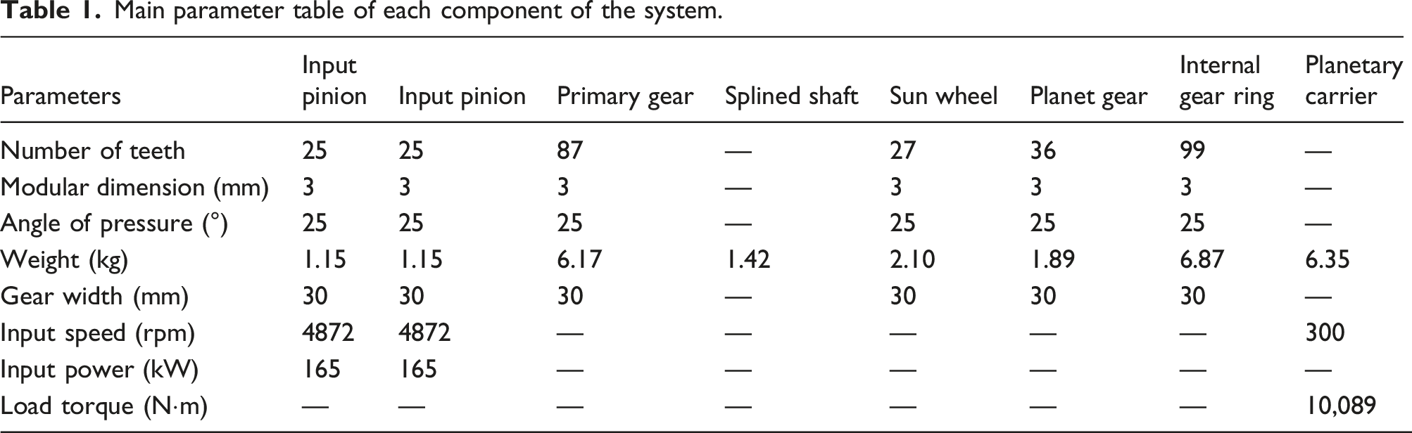
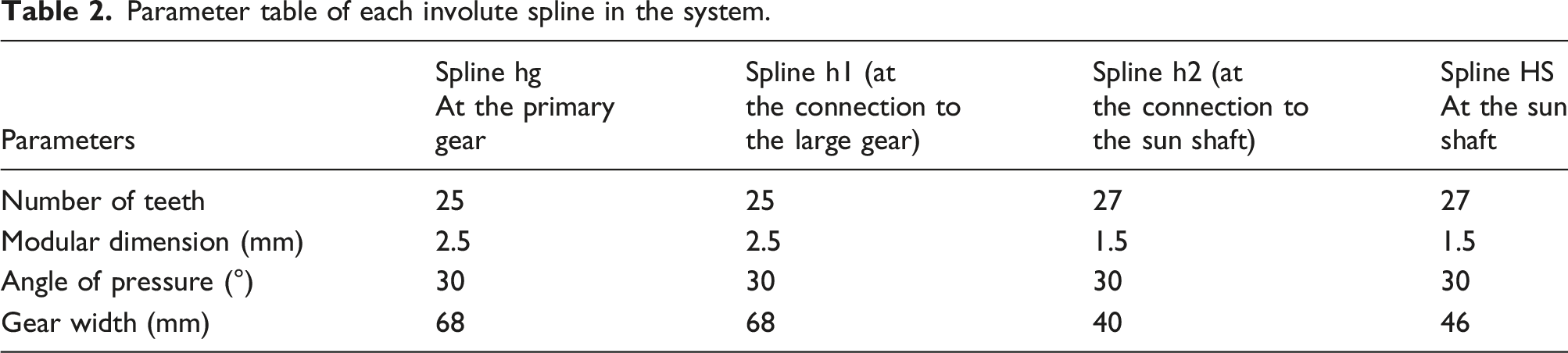
The transmission system studied in this paper is a dual-input two-stage gear transmission system. The first stage adopts a parallel-shaft transmission configuration, and the rotational speed and torque from the engine are transmitted to the transmission system by two input pinions and initially reduced. The second stage is a planet gear transmission with a typical 2K-H configuration. It distributes power to the planet gears and transmits power from the planet carrier to the rotor shaft. The first and second stages of the system are connected via an involute spline shaft. Based on the motion relationships among the transmission components, a simplified schematic of the parallel-shaft planetary gear system is shown in Figure 1. Key parameters of the transmission system are listed in Tables 1 and 2. Three-dimensional model and structural diagram of parallel-shaft-planet gear system. Main parameter table of each component of the system. Parameter table of each involute spline in the system.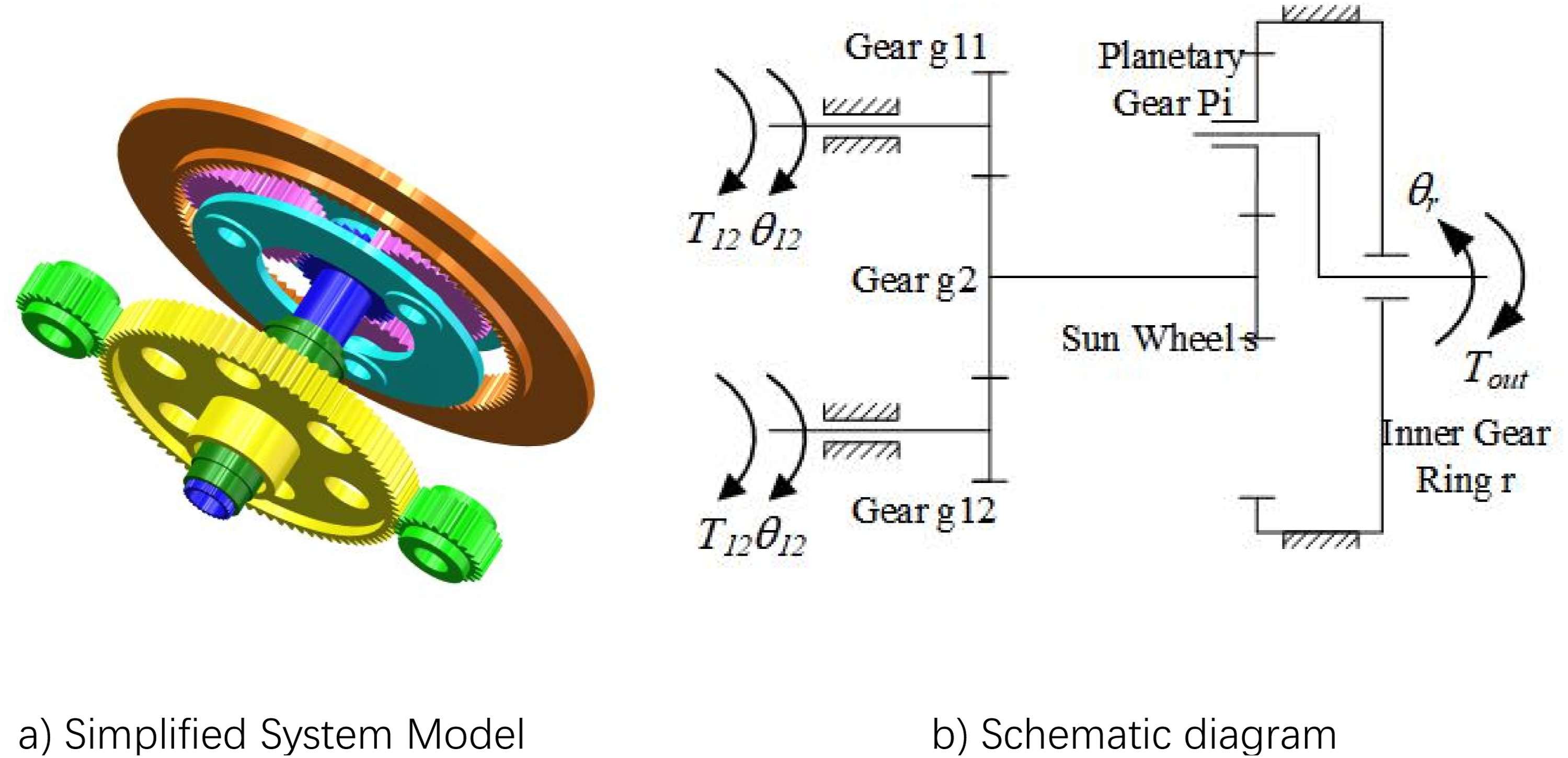
This parallel-shaft planetary gear system combines the advantages of parallel-shaft transmissions and planet gear transmissions. It features a simple and compact structure, high load capacity, and high transmission efficiency. Therefore, it satisfies the requirements of light helicopter main gearboxes for high reliability, high efficiency, and compact installation space. Based on the parameters of a specific helicopter main gearbox, the input power of the transmission system is set to 330 kW. The transmission efficiencies of both gear stages are 98%, and the rated output speed of the rotor shaft is 300 rpm.
Time-varying mesh stiffness of gear pairs
The mesh stiffness of the gear pair 20 is a direct index to measure the deformation resistance of the gear pair during meshing. It exhibits strong time-varying characteristics. Accurately calculating the mesh stiffness of the gear pair and studying the influence law of various influencing factors on mesh stiffness will directly affect the research on the dynamic characteristics and load-sharing characteristics of the parallel-shaft-planet gear system.
The transmission gears in all stages of the system studied are spur gears, and there is no axial force during operation. Therefore, according to the definition of gear-pair mesh stiffness by the Japan Society of Mechanical Engineers, mesh stiffness is defined as the ratio of the normal load to the normal deformation of the meshing tooth surface per unit face width. 21
The formula for calculating the mesh stiffness is: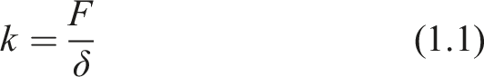
It is clear that the mesh stiffness of a single tooth pair is calculated in this case. However, to ensure the transmission performance of an actual gear transmission design, the contact ratio of gear pairs is usually greater than 1. This means that multiple tooth pairs may be in mesh simultaneously during the actual meshing process, which is also the main reason for the time-varying characteristics of mesh stiffness.
For first-level parallel-shaft drives, the single-gear mesh stiffness of the gear pair obtained from Equation (1.1) can be superimposed based on the meshing cycle 
Double-gear meshing time 

For the second-stage planet gear transmission, since the inner ring gear is fixed to the housing, the meshing frequency 
There is a unique meshing phase difference between the external gear pair and the internal gear pair in the planetary transmission system. That is, the stiffness of the mesh between each planet gear and the sun gear, as well as that between each planet gear and the ring gear, needs to be superimposed with a corresponding phase angle. Therefore, the overall mesh stiffness of the planet gear set can be obtained as follows:
Based on the structural parameters of each gear in the system, the potential energy method and finite element analysis, the mesh stiffness is calculated using MATLAB, ANSYS, and other software. By comparing the results, the mesh stiffness of the gear pairs in all stages of the parallel-shaft planetary gear system is obtained, and the influence of operating conditions, such as different speeds and loads, on mesh stiffness is explored. These results provide data support for subsequent research on the influence of different operating conditions on time-varying mesh stiffness, vibration, and load-sharing characteristics of the transmission system.
Potential energy method
The potential energy method22,23 is a mature and widely used method for calculating the time-varying mesh stiffness of gear pairs at present. Based on the law of conservation of energy, when two gears mesh, elastic potential energy is generated due to the contact and deformation of the tooth surfaces, and this energy is correlated with gear displacement and load. The mesh stiffness of the gear pair can then be obtained through analysis and calculation. The potential energy method has high calculation accuracy and high computational efficiency, and is suitable for rapid analysis of gear mesh stiffness.
The potential energy method comprehensively accounts for the contact 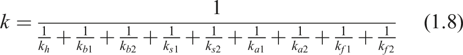
The numerical calculation program of the potential energy method is compiled by gear parameters and calculation formulas, and the parameters of the input big gear, planet gear, and internal gear meshing pair are set. The comprehensive mesh stiffness of each meshing pair obtained by solving is shown in Figure 2. The average mesh stiffness of the input-big gear is 3.28 × 10⁸ N/m, the minimum mesh stiffness of the single gear is 2.30 × 10⁸ N/m, and the maximum mesh stiffness of double teeth is 4.19 × 10⁸ N/m. The average mesh stiffness of planet-ring gear is 4.03 × 10⁸ N/m, the minimum mesh stiffness of the single gear is 3.02 × 10⁸ N/m, and the maximum mesh stiffness of the double gear is 4.97 × 10⁸ N/m. Solution of mesh stiffness of gear pair by potential energy method.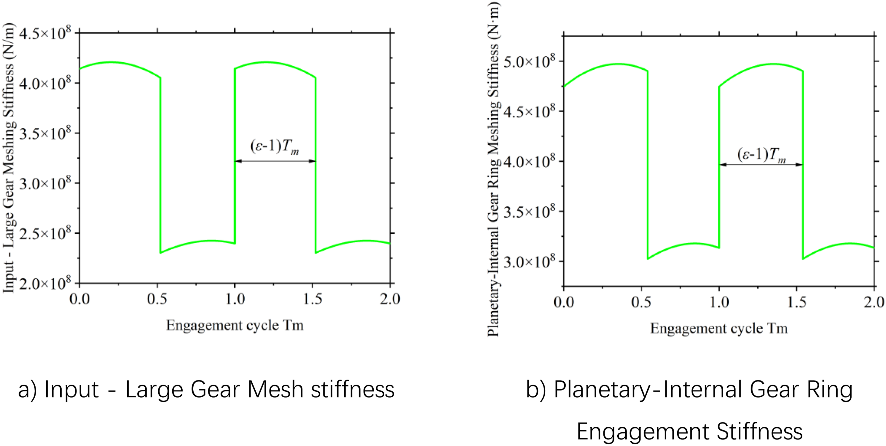
While keeping other parameters constant, the pressure angle Comparison of mesh stiffness at different pressure angles.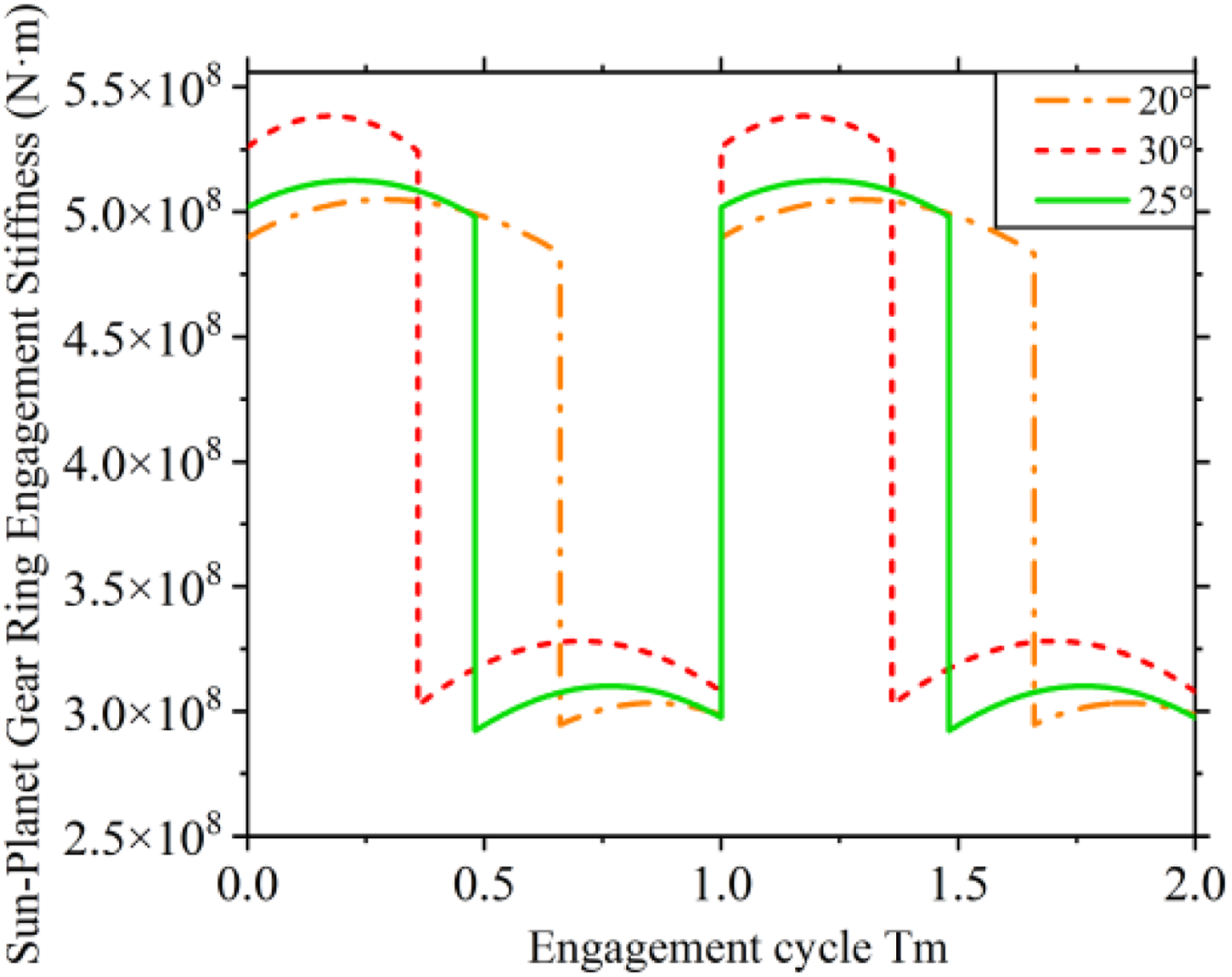
It can be found that the mesh stiffness of the gear pair increases as the pressure angle increases. This means that choosing a larger pressure angle can improve the bearing capacity of the gear and meet the design requirements of high load capacity, high speed, and high precision. However, an increased pressure angle will lead to a decrease in the contact ratio, a decrease in the meshing area during double-tooth contact, an increase in vibration and impact, and an increase in the radial force component of the gear. Therefore, all gears in the parallel-shaft planetary gear transmission system adopt a pressure angle of 25°.
While keeping the overall dimensions and other parameters of the model constant, the gear module is varied to 2.5 mm, 3 mm, and 4 mm. The mesh stiffness of the sun–planet gear pair with different modules is calculated, as shown in Figure 4. It can be found that the mesh stiffness of the gear pair increases as the module increases. This is related to the increase in gear tooth size, tooth-root strength, and contact stiffness when the module is increased. However, at this time, the number of gear teeth decreases, the contact ratio decreases, and the meshing area during double-tooth contact decreases. This means that the mesh stiffness of the gear pair can be relatively improved by selecting a larger module while ensuring that the overall size of the gear remains unchanged. However, if the module is too large, there will be too few teeth, and the stress on a single tooth will increase. Therefore, all gears in this system adopt a module of Comparison of mesh stiffness of different modules.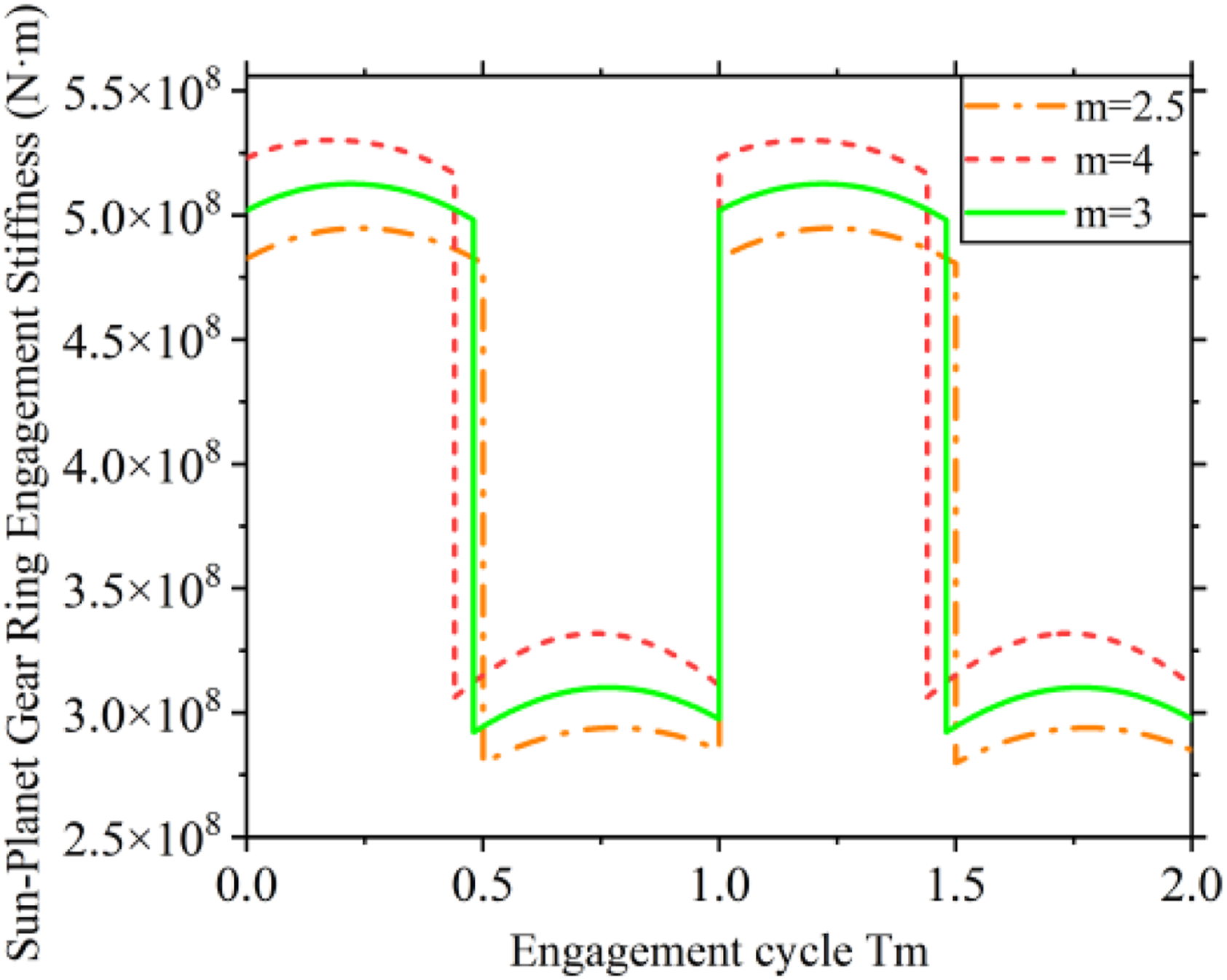
Finite element method
Both the finite element method 24 and the potential energy method are commonly used to calculate time-varying mesh stiffness. In contrast, the potential energy method can quickly obtain the mesh stiffness of a gear pair with a simple structure, while the finite element method can obtain the mesh stiffness of gear pairs with complex structures while ensuring solution accuracy. Moreover, when finite element analysis is used, many factors, such as hub deformation, backlash, and material properties, can be considered; therefore, the calculation accuracy is higher.
To shorten the simulation time, the mesh stiffness of the sun–planet gear pair is analyzed using the finite element method and compared with the results obtained by the potential energy method. First, the three-dimensional model is simplified by omitting features such as chamfers and threaded holes, and a partial-tooth model is extracted from the complete gear model for simulation. Then, HyperMesh software is used to generate the finite element mesh, thereby improving the mesh quality and ensuring the calculation accuracy of the finite element simulation model for gear-pair mesh stiffness. Finally, the mesh file is imported into ANSYS for transient dynamic analysis.
The model is sectioned, as shown in Figure 5. The sectioned model is then imported into HyperMesh, where a hexahedral mesh is generated using C3D8R elements. The mesh is refined around the gear teeth and tooth roots to improve the calculation accuracy. After mesh generation is completed, the gear-pair model contains 263,592 elements, with a minimum element size of 0.14 mm. The mesh model is then imported into ANSYS for transient dynamic analysis. Simplified model of sun-planet gear and finite element mesh model.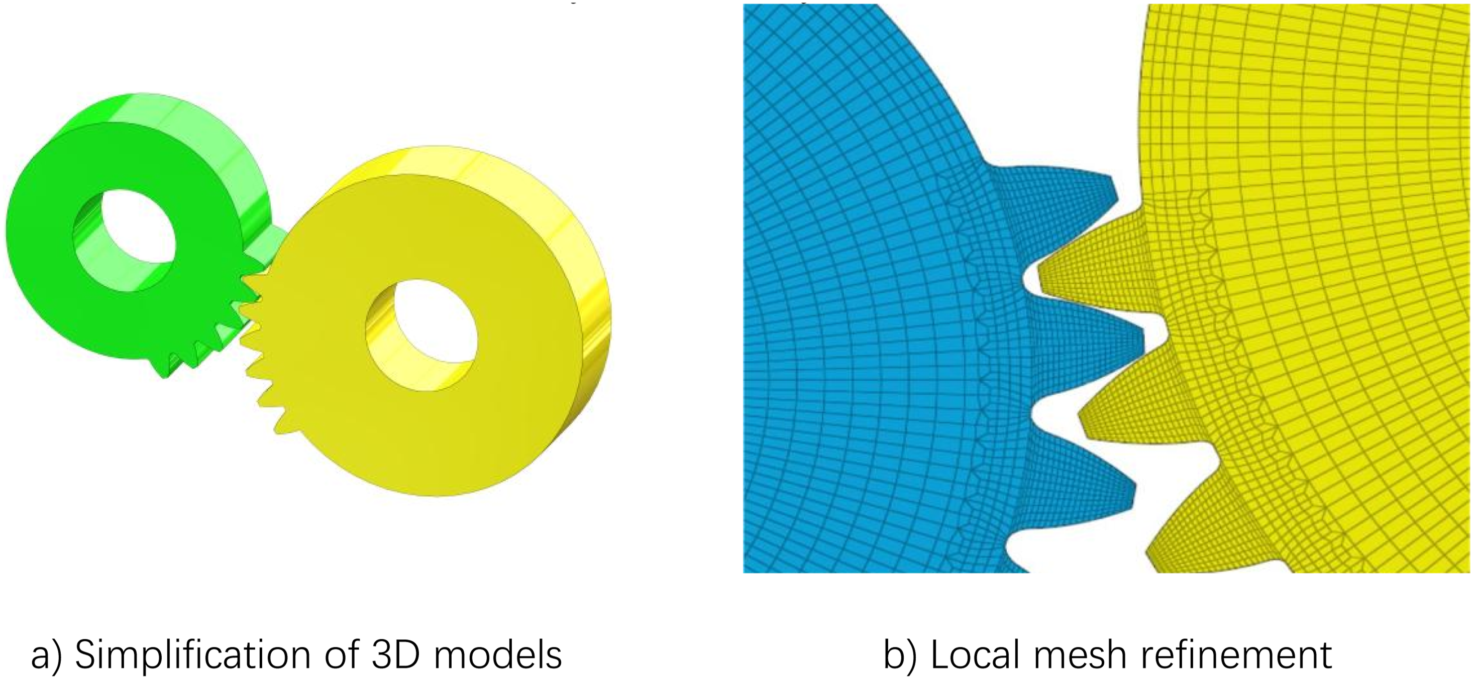
To study the influence of different loads on mesh stiffness, it is necessary to apply a load of 800 N·m, so it is necessary to verify the maximum stress. The maximum stress is 586.77 MPa, which is lower than the yield limit of the material (the yield limit can reach more than 1000 MPa after carburizing the surface of 18CrNiMo7-6). That is, plastic deformation will not occur.
The primary simulation steps are as follows: (1) Material properties are defined. All components in this study are made of 18CrNiMo7-6 steel, with an elastic modulus of
According to the theoretical description above, the same input parameters are used, and the mesh stiffness curves of each gear pair calculated using the potential energy method are obtained in MATLAB. The angular displacement results from ANSYS are extracted, and the angular displacement difference curve of the sun–planet gear pair under no-load conditions is calculated and plotted. Then, the time-varying mesh stiffness curve is obtained according to the formula, as shown in Figure 6(a). Compared with the results obtained by the potential energy method, the accuracy of the mesh stiffness simulation model established in ANSYS is verified. These results provide methodological and theoretical support for the subsequent study of the influence of different operating conditions on the time-varying mesh stiffness of the parallel-shaft planetary gear system. Mesh stiffness of sun-planet gear pair.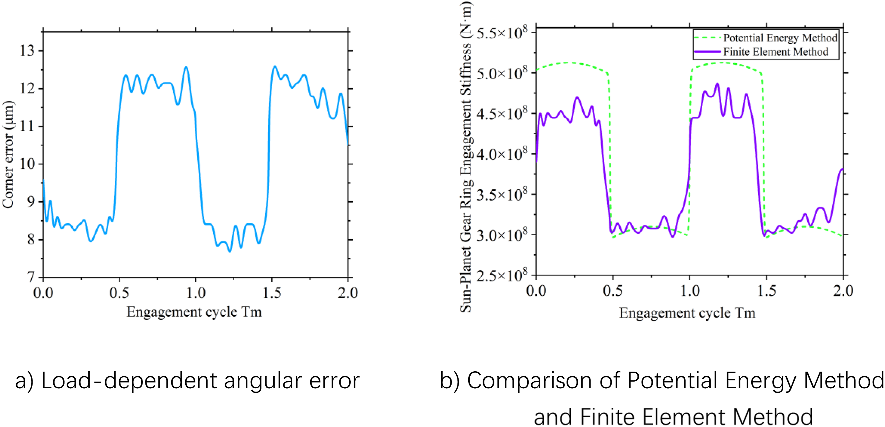
After analyzing the simulation data, it can be seen that the no-load angular displacement difference of the sun–planet gear pair is periodic, but its average value is very small, approximately
The mesh stiffness of the single-tooth contact region obtained by the two methods agrees well. The average single-tooth mesh stiffness calculated by the finite element method is 3.05 × 10⁸ N/m by the finite element method and 3.18 × 10⁸ N/m by the potential energy method. The relative error is 4.3%. Compared with theoretical calculation methods such as the potential energy method, the finite element method considers factors that are closer to actual operating conditions, and its calculation results are often smaller than theoretical calculations. Therefore, the relative errors of the overall average mesh stiffness and the average single-tooth mesh stiffness are within the acceptable range. The accuracy of the finite element model is further verified, laying a foundation for the subsequent study of the influence of different operating conditions on mesh stiffness.
Effects of different operating conditions on time-varying mesh stiffness
Effect of different rotational speeds on time-varying mesh stiffness
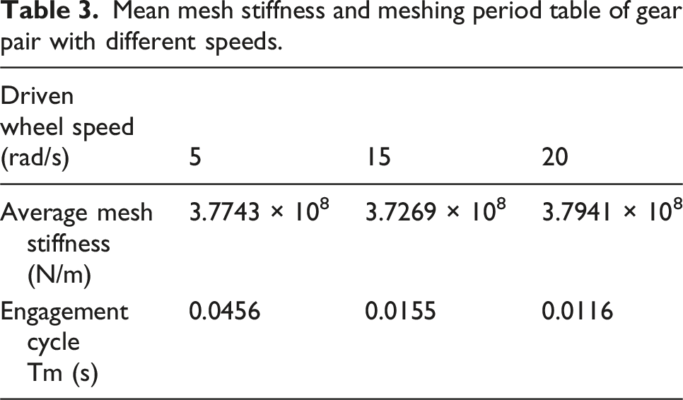
Control other parameters unchanged, and set the different input pinion speeds to 5 rad/s, 15 rad/s, and 20 rad/s. Set the load torque to 200 N·m. Based on the finite element theory and simulation settings described in the Section ‘Time-varying mesh stiffness of gear pairs’, the time-varying mesh stiffness curves of the gear pairs under different input rotational speeds are obtained, as shown in Figure 7. Mesh stiffness change curve of gear pair at different speeds.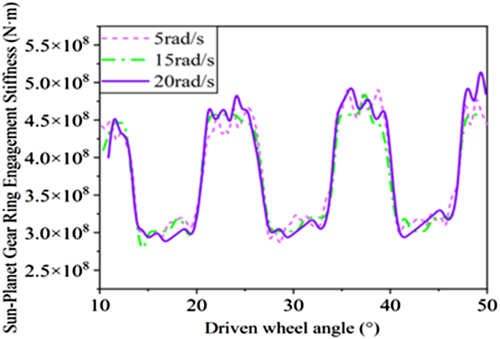
Mean mesh stiffness and meshing period table of gear pair with different speeds.
Effect of acceleration conditions on time-varying Engagement stiffness
Set different accelerations of 100 rad/s2, 200 rad/s2 and 300 rad/s2. Set the load torque to 200 N·m. Based on the finite element theory and simulation settings described in the Section ‘Time-varying mesh stiffness of gear pairs’, the time-varying mesh stiffness curves of the sun-planet gear pair under different input acceleration conditions are calculated, as shown in Figure 8. The average mesh stiffness of the gear pair under different accelerations is shown in Table 4. Mesh stiffness change curve of gear pair under different accelerations. Table of mean mesh stiffness of gear pair at different accelerations.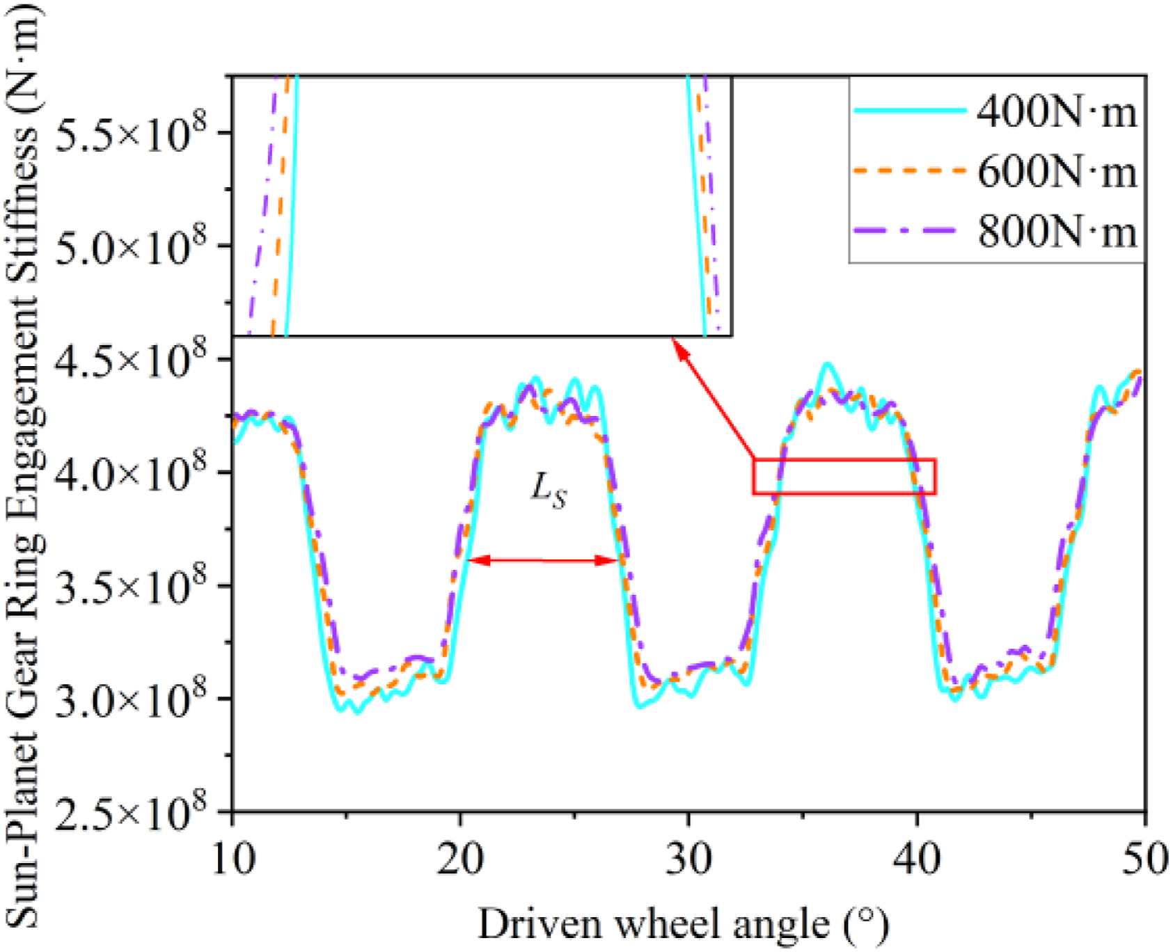
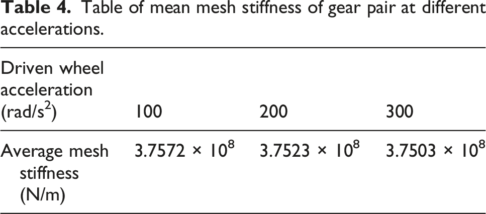
From the simulation data under three acceleration conditions, it can be seen that with the increase in acceleration, the average change range of mesh stiffness is small, and the fluctuation ranges of the curves are close. Therefore, it is considered that there is no direct relationship between acceleration and the mesh stiffness of the gear pair. However, there will be inertial force in the acceleration process, and with the increase in acceleration duration, the rotation speed will gradually increase, and the mesh stiffness fluctuation will increase, thus increasing the mesh impact and enhancing negative effects such as vibration and noise.
Effect of different load conditions on time-varying Engagement stiffness
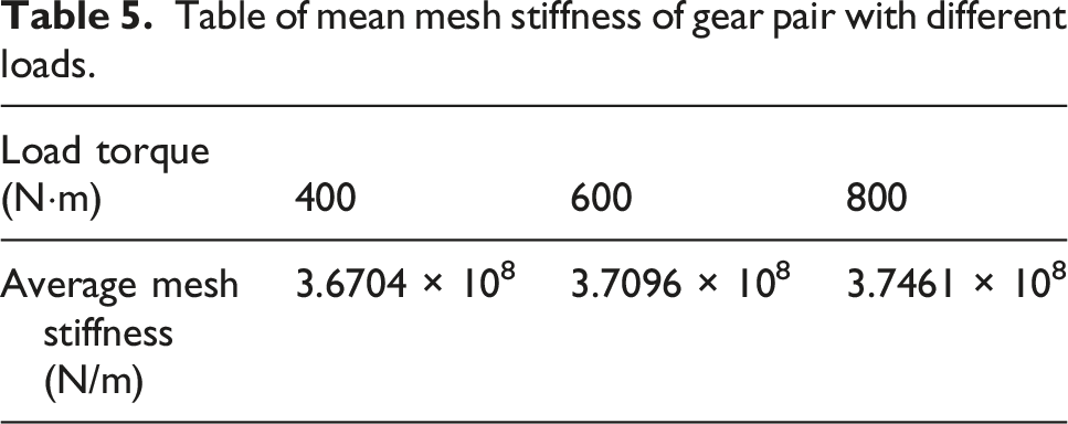
Set the load torques of different driven wheels as 400N·m, 600N·m, and 800 N ·m. Set the input speed to 3 rad/s. The time-varying mesh stiffness curves of the sun-planet wheel under different loads are calculated, as shown in Figure 9. Mesh stiffness change curve of gear pair with different loads.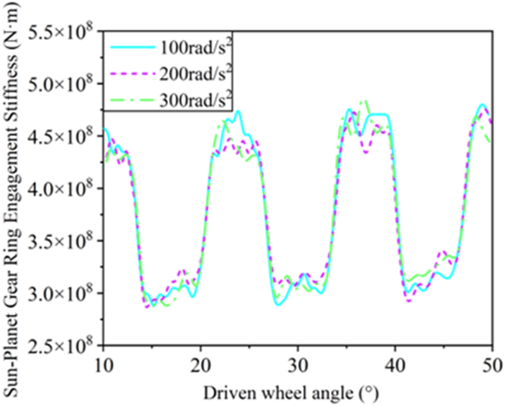
Table of mean mesh stiffness of gear pair with different loads.
Compared with the influence of gear structural parameters, including pressure angle and modulus, on mesh stiffness, the influence of operating-condition parameters, including input speed, acceleration, and load torque, on mesh stiffness and the fluctuation range of the gear pair is relatively small. However, the operating-condition parameters will affect the excitation frequency of time-varying mesh stiffness, resulting in meshing force fluctuation, vibration impact, and so on, which further affects the dynamic vibration, load-sharing, and other transmission performance of the power split gear system.
Dynamic combined mesh error
Eccentricity error
Due to limitations in manufacturing technology, material defects, installation errors, etc., the components in the system may deviate from their mass centers, that is, eccentricity errors. Based on the analysis of the relative displacement of gear pairs, the projections of eccentricity errors of input gear 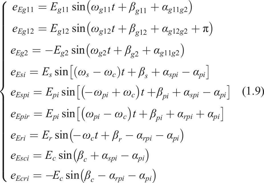
Dynamic comprehensive mesh error
In the actual production and manufacturing of gears, the actual geometric parameters such as tooth profile, tooth lead, and other factors will deviate from the standard design. The resulting errors are tooth profile error, tooth lead error, gear pitch deviation, and so on. These errors will have a great influence on the accuracy and stability of the gear transmission system.
The factors such as gear profile deviation, cumulative deviation of gear pitch, and meshing phase of each gear pair are considered, and the above mesh error excitation is transformed into a displacement change on the mesh line. Because these errors change periodically, the simple harmonic function and mesh frequency are used to transform the errors into the corresponding mesh lines of each gear pair for subsequent research. The formula for calculating the equivalent mesh error of each gear pair is as follows: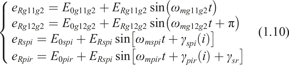
By combining the eccentricity error and equivalent mesh error of the above components, the dynamic comprehensive mesh error of each gear pair is obtained. The dynamic comprehensive mesh errors of the input pinion–primary gear pair, sun–planet gear pair, and planet–ring gear pair projected on their respective mesh lines are as follows: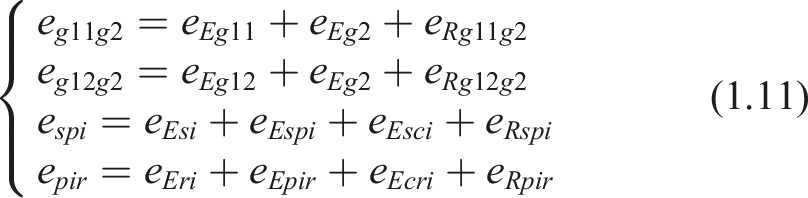
Gear flank clearance
The influence of backlash cannot be ignored when studying the dynamic characteristics and load-sharing characteristics of the gear transmission system.
The backlash, relative deformation displacement, error excitation, etc., are equivalent to the meshing line. The backlash function used in the study is shown in Formula (1.12).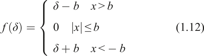
Calculation of other parameters
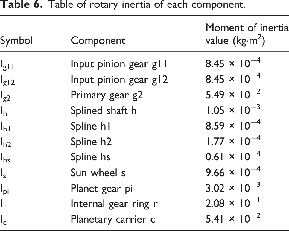
Each gear in the parallel-shaft planetary gear system is assumed to be a uniform disk, and the other components are assumed to have uniform mass distributions. Ignoring structural features such as chamfers and bolt holes in the system, parameters such as the moment of inertia and mesh damping are calculated based on the simplified model.
Moment of inertia
Table of rotary inertia of each component.
Single-gear Engagement stiffness of spline pair
The primary gear and spline shaft, and the spline shaft and sun gear shaft, are connected by flat-root involute splines. Based on the standard involute gear mesh-stiffness calculation method, the single-tooth mesh stiffness of the internal and external spline pairs is obtained. Based on the above finite element simulation method for solving the mesh stiffness of the sun–planet gear pair, the primary gear–spline shaft assembly and spline shaft–sun gear shaft assembly are retained. The mesh is generated using HyperMesh, and the mesh file is imported into ANSYS for simulation analysis. The input speed is set to 3 rad/s, and the load torque is set to 200 N·m. After the simulation is submitted, the simulation results are extracted, and the single-tooth mesh stiffnesses of the two spline pairs are calculated as follows: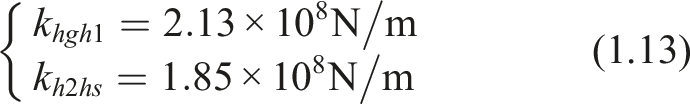
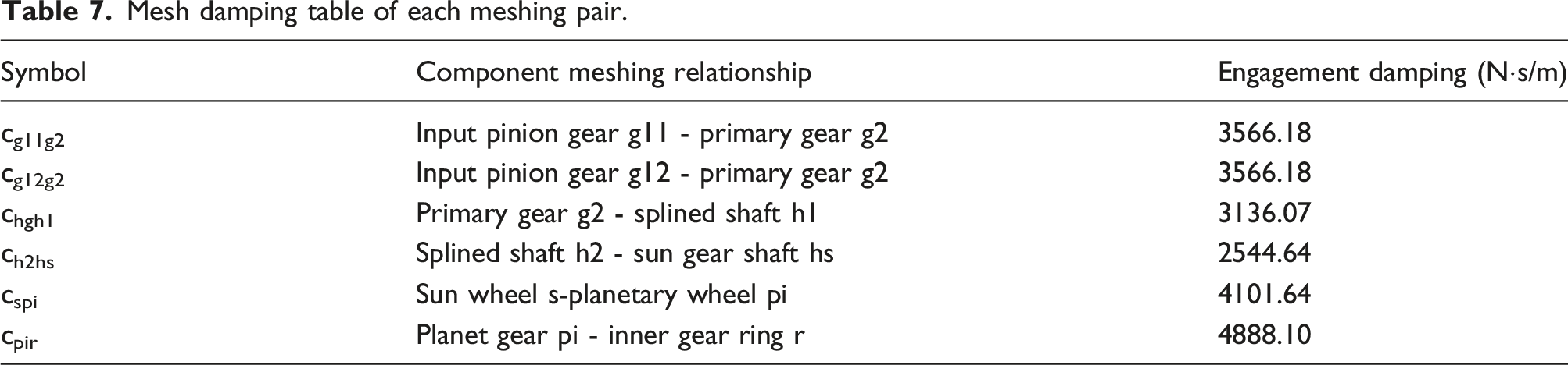
Mesh damping calculation
Damping calculation in the gear transmission system is a hot spot and a big difficulty at present. The existing research mostly defines damping as a parameter related to stiffness. Therefore, the formula for calculating the mesh damping of each gear pair is defined as: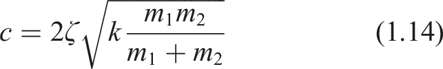
The mesh damping expression for the spline meshing pair is: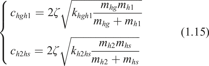
Mesh damping table of each meshing pair.
Bearing support stiffness and support damping
Bearing support stiffness is the ability of the bearing to resist deformation under load, and support damping is related to energy dissipation. Both are often influenced by many factors, such as bearing type, bearing preload, and lubrication conditions. Support stiffness and damping affect the vibration, noise, and stability of the transmission system. Therefore, studying the influence of support stiffness on the vibration characteristics of the system during operation can provide theoretical support for subsequent vibration control and transmission-performance optimization. According to the model parameters and analogy related research, it is assumed that the support stiffness in X direction and Y direction of each component is equal, that is,
Influence of excitation parameters on system vibration response under steady-state conditions
Because gear vibration is periodic but non-stationary, the vibration response is measured using the peak-to-peak value of vibration displacement. This index can fully reflect the influence of the maximum deformation range and the change of operating-condition parameters on the dynamic vibration of the gear system. It is convenient for evaluating the vibration intensity, and it can provide a basis for optimizing the gear system to reduce vibration and noise. Therefore, the peak-to-peak value of vibration displacement is selected as the evaluation index to study the influence of dynamic excitation parameters on the vibration response of the system.
Effect of time-varying mesh stiffness on system vibration response
Time-varying mesh stiffness is one of the excitation parameters that has a great influence on the dynamic vibration characteristics of the gear transmission system. To study the influence of the time-varying mesh stiffness of gear pairs and spline pairs on the vibration response, the mesh stiffnesses of the gear pairs and spline pairs are set to 0.5, 1.0, 1.5, 2.0, and 2.5 times their original values, respectively, under steady-state operating conditions, while keeping the other parameters of the theoretical model unchanged. The vibration response of each component is extracted, and the curve of the peak-to-peak value of vibration displacement with respect to mesh stiffness is drawn.
Variation in gear pair mesh stiffness
The mesh stiffness of each gear pair in the system is set to vary synchronously. The curve of the peak-to-peak value of the vibration displacement response of each component of the system, changing synchronously with the mesh stiffness of all gear pairs in the system, is shown in Figure 10. Variation curve of vibration displacement peak-to-peak value with gear mesh stiffness.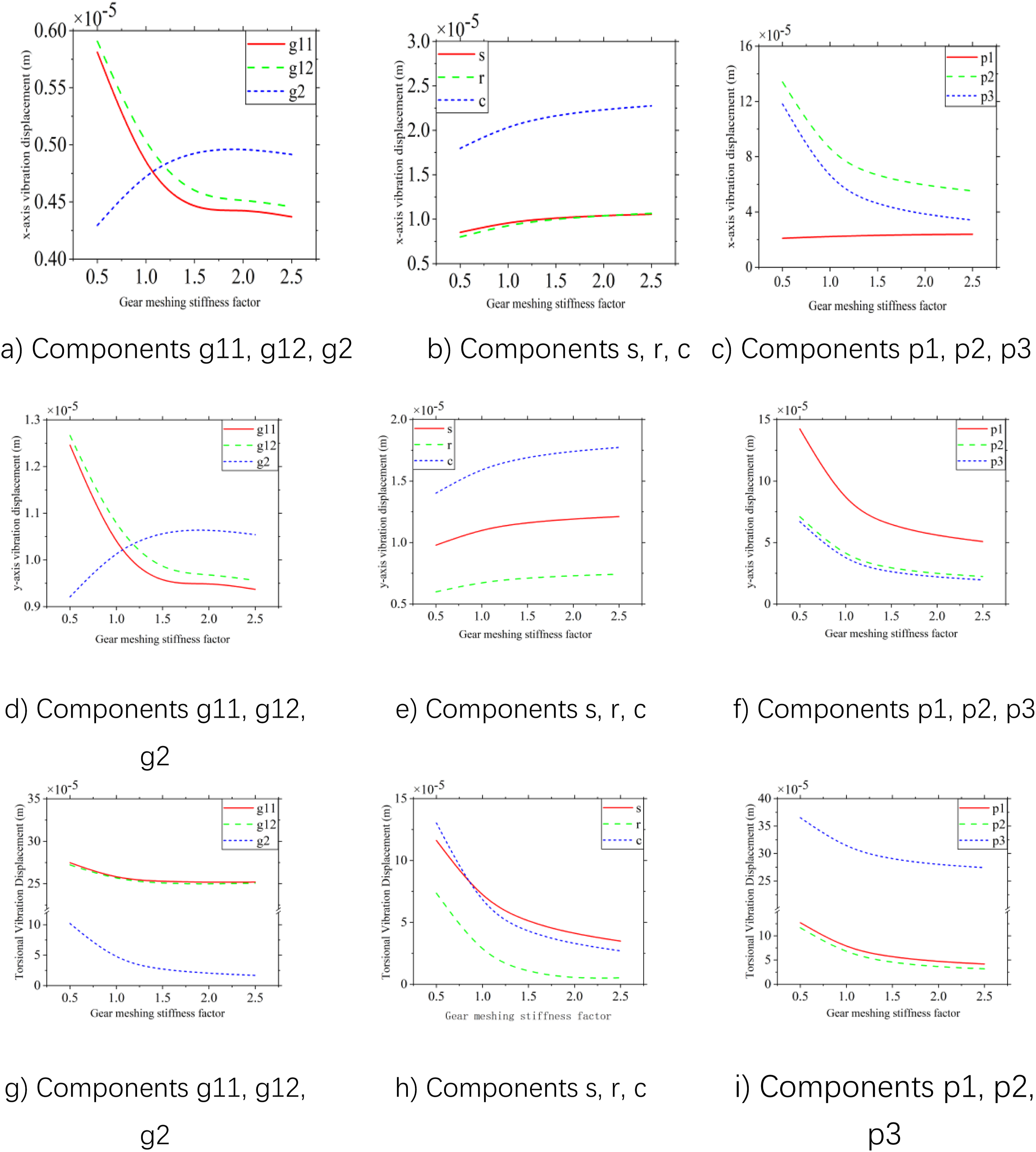
It can be seen from the figure that the peak-to-peak values of the X-direction, Y-direction, and torsional vibration displacements of input gears g11 and g12 all decrease with the increase in the overall mesh stiffness, and the changing trend gradually slows down. The X-direction, Y-direction, and torsional vibration displacements of the primary gear decrease with the increase in mesh stiffness, and the changing trend gradually slows down. The X- and Y-direction vibration displacements of the sun gear, ring gear, and planet carrier in the planetary components increase with the increase in mesh stiffness. It can also be seen intuitively that the vibration displacement of the planet carrier is larger than that of the sun gear and ring gear, and the torsional vibration displacement decreases with the increase in mesh stiffness. The X-direction, Y-direction, and torsional vibration displacements of the planet gears decrease with the increase in mesh stiffness, and the torsional vibration displacement of planet gear p3 is always greater than those of planet gears p1 and p2. These results are consistent with the steady-state vibration analysis results in the previous section.
Variation in single-gear Engagement stiffness of splined shafts
The mesh stiffness of the two spline pairs of the spline shaft, hg-h1 and h2-hs, is set to vary synchronously. The curve of the torsional vibration response of system components versus the mesh stiffness of the spline pairs is shown in Figure 11. Variation curve of vibration displacement peak-to-peak value with spline mesh stiffness.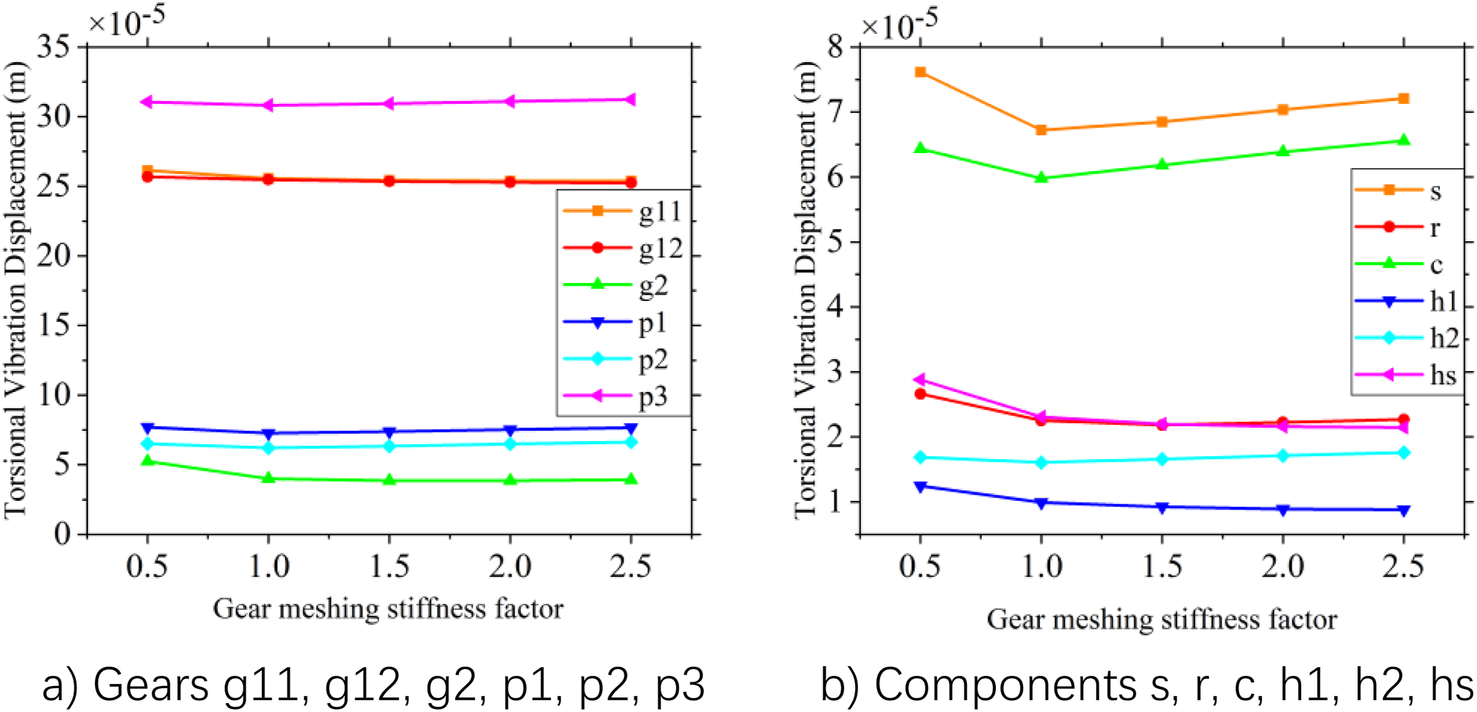
As can be seen from the figure, when the mesh stiffness of the spline pairs in the system increases synchronously, the peak-to-peak values of the torsional vibration displacements of the primary gear, spline h1, and spline hs show a downward trend, and the variation amplitude tends to stabilize when the single-tooth mesh stiffness continues to increase. The peak-to-peak curves of the torsional vibration displacements of spline h2, the sun gear, the planet carrier, and the ring gear show a trend of first decreasing and then increasing. The torsional vibration displacements of pinions g11 and g12 change only slightly.
The variation in spline-pair mesh stiffness mainly affects the torque transmission boundary between the parallel-shaft stage and the planetary gear stage. As the spline-pair mesh stiffness increases, the relative torsional deformation between the primary gear and the sun gear decreases. Therefore, the torsional vibration responses of the primary gear, spline h1, and spline hs are reduced. However, for downstream components such as spline h2, the sun gear, planet carrier, and ring gear, the increase in stiffness also enhances the transmission of dynamic excitation from the preceding stage to the planetary gear stage, causing their vibration responses to first decrease and then increase. This phenomenon indicates that the spline pair plays an inter-stage coupling regulation role in the system rather than acting as a simple rigid connection.
Effect of error excitation on system vibration response
Equivalent error
Due to various manufacturing errors, gear surface wear, and other factors, tooth profile errors, tooth lead errors, and pitch deviations widely exist in practical systems. Here, these three types of errors are projected onto the mesh line and defined as equivalent mesh errors. To study the influence of the equivalent mesh errors on the vibration response of the system, the equivalent mesh errors of each gear pair in the system are set to vary as 0 μm, 50 μm, 100 μm, 150 μm, and 200 μm, and the equivalent mesh errors of all gear pairs change synchronously. The curve of the torsional vibration response of each part of the system with the equivalent mesh error is shown in Figure 12. Variation curve of peak-to-peak value of vibration displacement with equivalent error.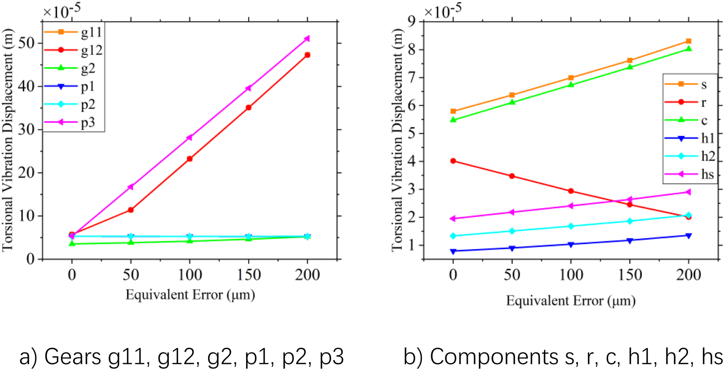
As can be seen from the figure, the peak-to-peak values of the torsional vibration displacements of the two input pinions and the primary gear in the first stage increase with the increase in equivalent error excitation. Among them, the variation gradient of the torsional vibration displacement amplitude of the input pinions is larger. The peak-to-peak values of the torsional vibration displacements of each spline, the sun gear, and the planet carrier all increase with the increase in equivalent error, while the fluctuation range of the torsional vibration displacement of the ring gear decreases with the increase in equivalent error. The peak-to-peak values of the torsional vibration displacements of planet gears p1 and p2 are insensitive to the change in equivalent error, and the peak-to-peak value of the torsional vibration displacement of planet gear p3 increases with the increase in equivalent error due to the installation phase and error excitation phase. This is also the reason why the peak value of the torsional vibration displacement of planet gear p3 is larger in the steady-state response analysis in the previous section.
Eccentricity error
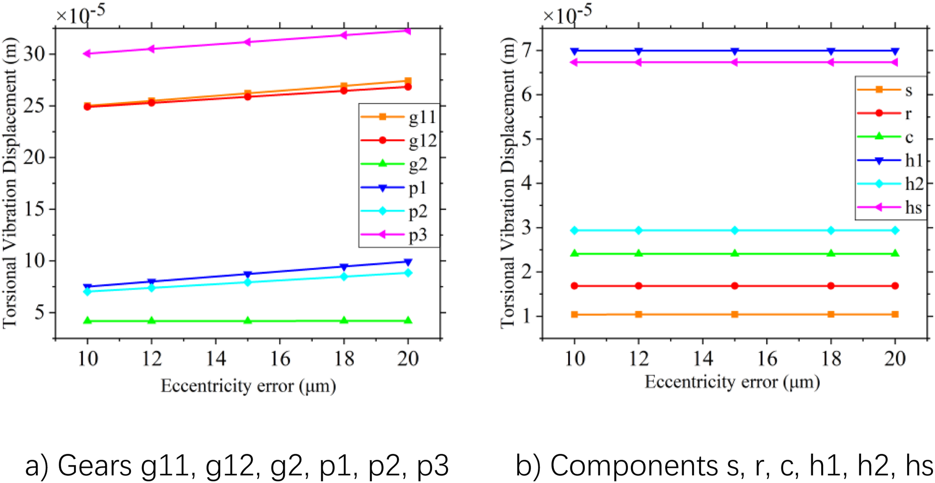
In the process of manufacturing and assembly of the gear system, due to influencing factors such as blank material and manufacturing accuracy, the actual rotation centers of components in the system will deviate from their ideal positions. To study the influence of eccentricity error on the vibration response of the system, under the premise of keeping other parameters unchanged, the eccentricity error phase of each gear is set to 0, and the magnitudes are set to 10 μm, 12 μm, 15 μm, 18 μm, and 20 μm, respectively. The eccentricity errors of all components in the system are set to vary synchronously, and the curves of the peak-to-peak values of the X-direction translational, Y-direction translational, and torsional vibration responses of all components with the eccentricity errors are obtained, as shown in Figures 13–15. Variation curve of peak-to-peak value of x-direction vibration displacement with eccentricity error. Variation curve of peak-to-peak value of y-direction vibration displacement with eccentricity error. Variation curve of peak-to-peak value of torsional vibration displacement of system components with eccentricity error.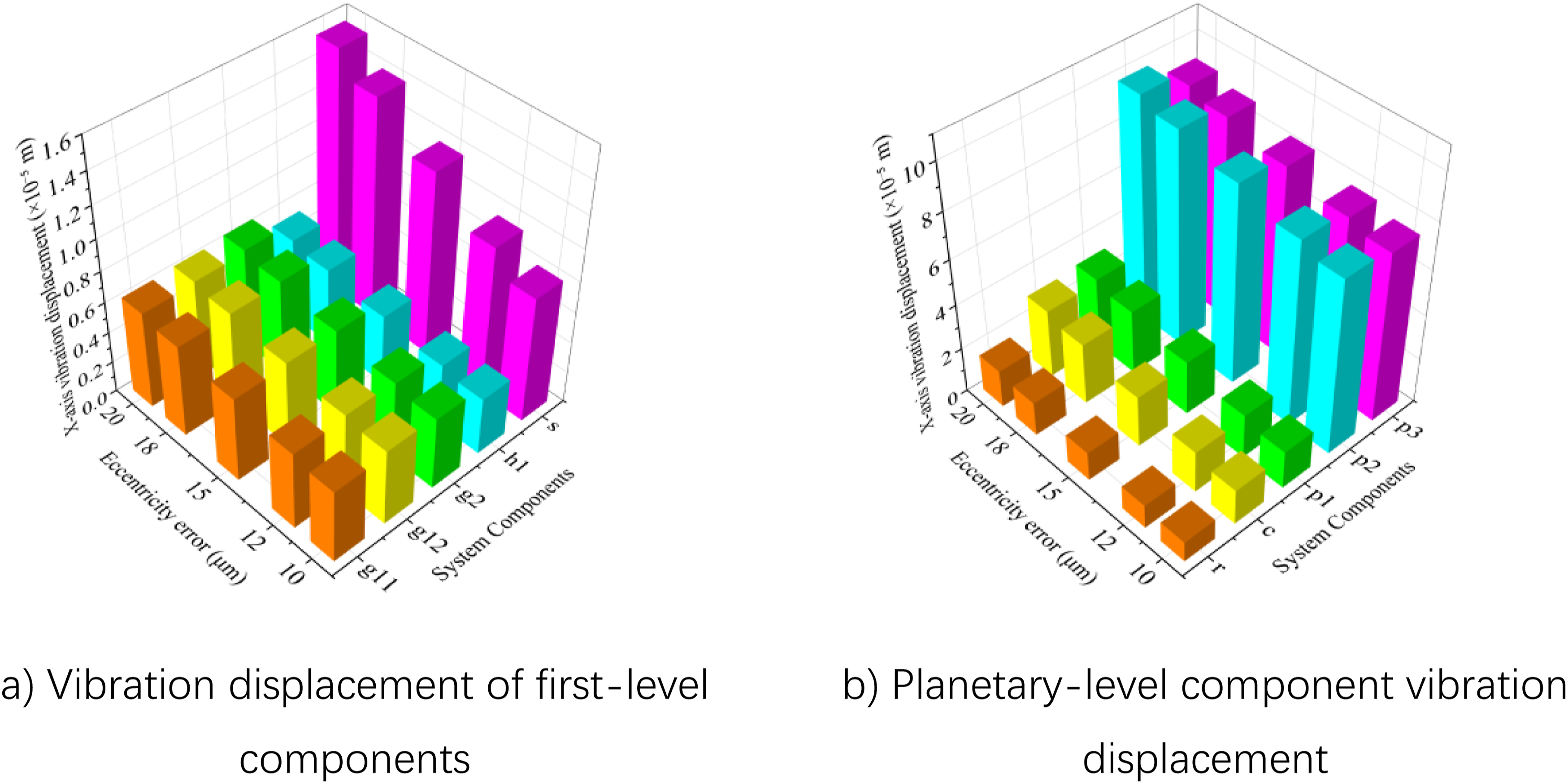
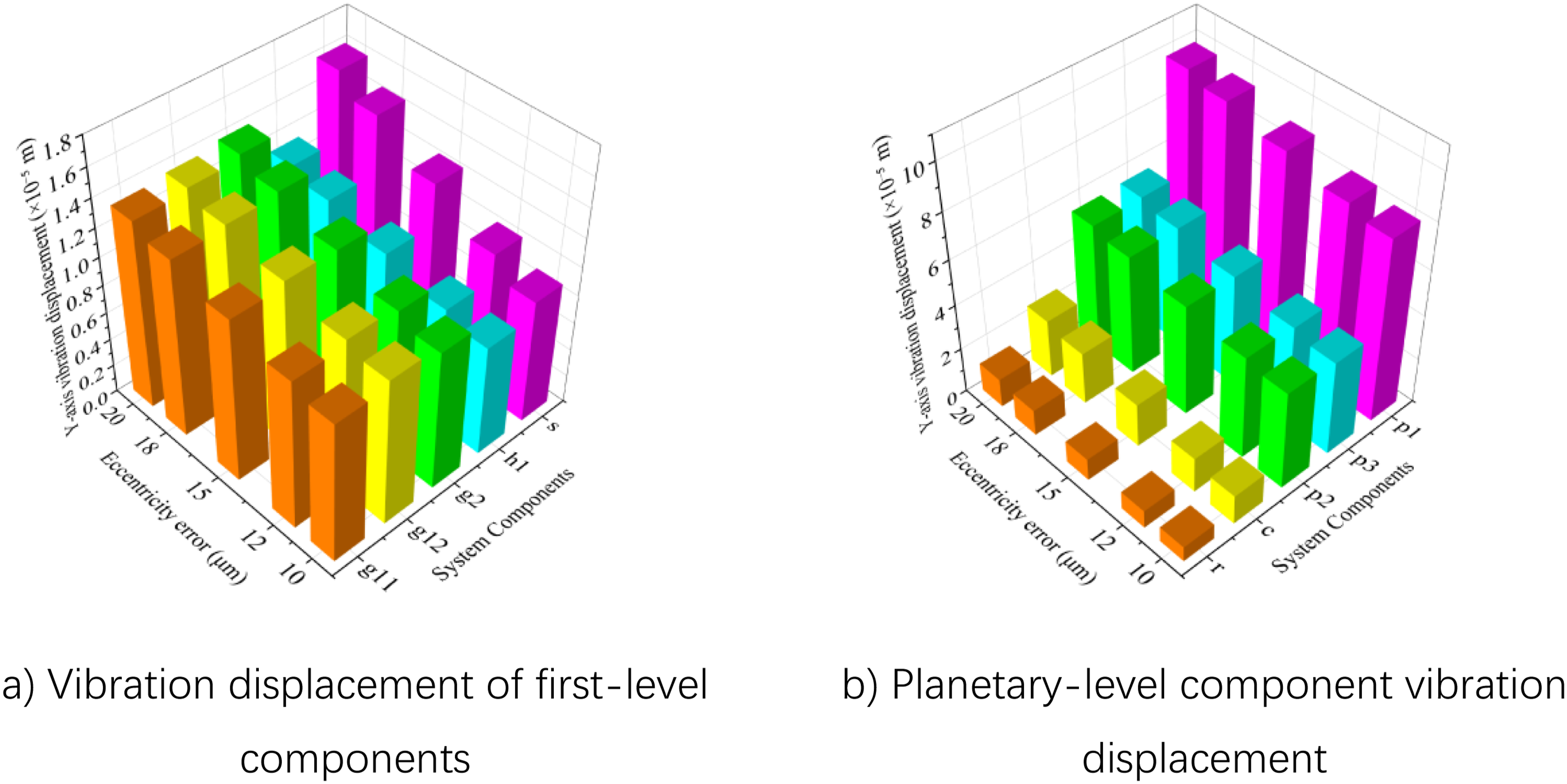
As can be seen from Figures 13 and 14, the peak-to-peak values of the vibration displacements of each component in the system along the X- and Y-directions all increase with the increase in eccentricity error. As shown in Figures 13(a) and (b), the peak-to-peak values of the X-direction vibration displacements of the sun gear and planet gears in the system increase significantly with the increase in eccentricity error. When the phase of the eccentricity error is 0, as shown in Figures 14(a) and (b), the influence of eccentricity error on the Y-direction vibration displacement is greater than that on the X-direction vibration displacement, and the peak-to-peak variation gradient of the Y-direction vibration displacements of the sun gear and planet gears is greater than those of other components.
As can be seen from Figure 15, with the increase in eccentricity error, the peak-to-peak values of the torsional vibration displacements of the two input pinions and the planet gears increase, and the amplitude range of the torsional vibration displacement of the primary gear, the sun gear, the planet carrier, the ring gear, and the splines is insensitive to the change in eccentricity error.
Effect of support stiffness on system vibration response
To study the influence of bearing support stiffness on the vibration response of components of the parallel-shaft planetary gear system, other parameters in the theoretical calculation model are kept unchanged. The support stiffnesses of all components are set to be equal, and their values are set to 5 × 10⁷ N/m, 1 × 10⁸ N/m, 5 × 10⁸ N/m, 1 × 10⁹ N/m, and 5 × 10⁹ N/m, respectively. The synchronous variation curves of the torsional vibration displacement responses of each component with the overall support stiffness of the system are obtained, as shown in Figure 16. Variation curve of peak-to-peak value of torsional vibration displacement of system components with overall support stiffness.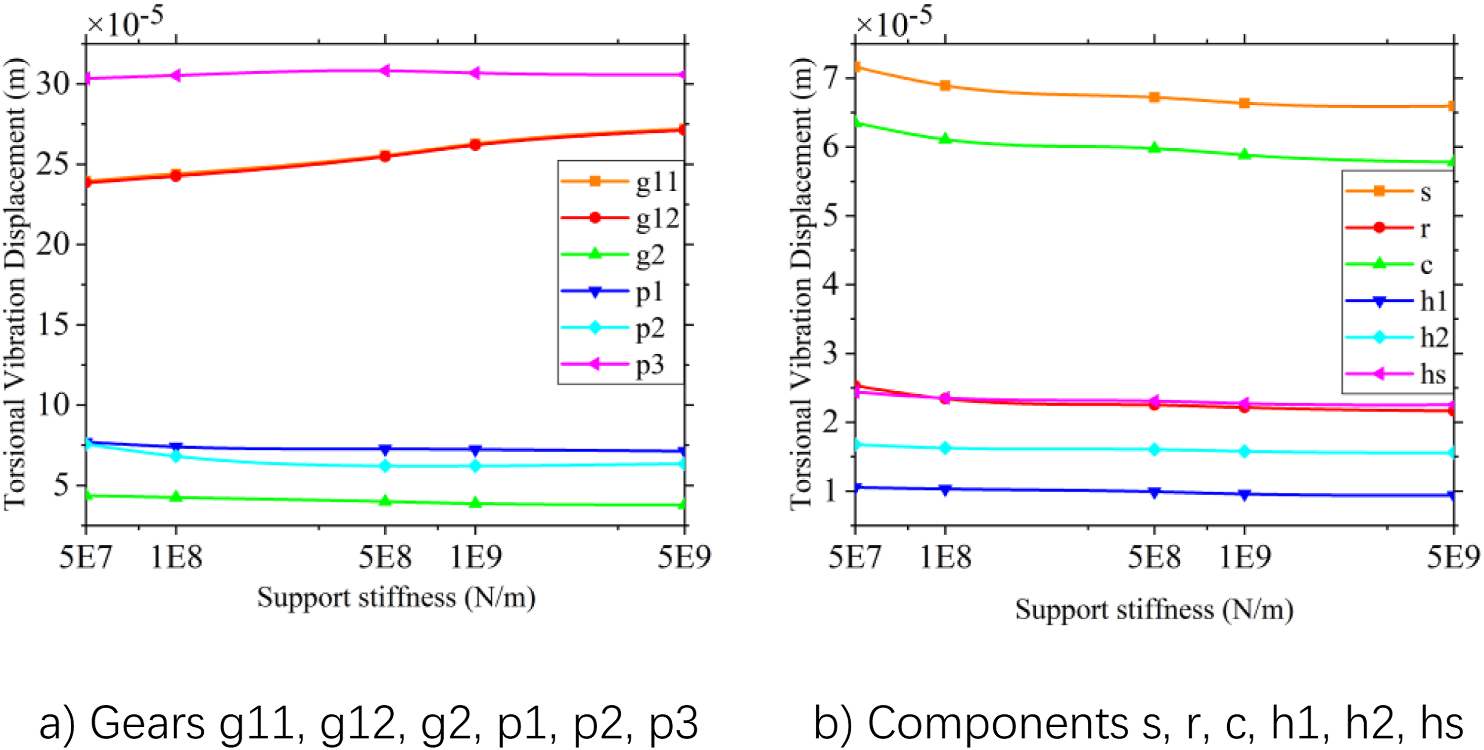
As can be seen from the figure, the peak-to-peak values of the torsional vibration displacements of the two input pinions in the first-stage transmission assembly of the system increase with the increase in the overall support stiffness of the system. There is no obvious change in the vibration range of the primary gear and planet gears. The torsional vibration range of each spline, the sun gear, the planet carrier, and the ring gear decreases slightly with the increase in support stiffness. Therefore, the torsional vibration range of each component in the system can be adjusted by adjusting the support stiffness.
Support stiffness has component-dependent effects on the torsional vibration responses of the system. With increasing support stiffness, the peak-to-peak values of the torsional vibration displacement of the two input pinions increase, whereas the torsional vibration ranges of the splines, sun gear, planet carrier, and ring gear decrease slightly. This indicates that higher support stiffness alters the vibration energy distribution between the input stage and the planetary gear stage, enhancing local responses at the input end while partially suppressing the responses of downstream components. Therefore, support stiffness does not act as a monotonically effective vibration-reduction parameter. For dual-input transmission systems, bearing support stiffness should be designed by considering the overall vibration levels of the input stage and planetary gear stage rather than being optimized based on the response of a single component.
Effect of splined shaft torsional stiffness on system vibration response
The spline shaft undertakes the task of connecting the first-stage parallel-shaft transmission with the second-stage planet gear transmission. To study the influence of the torsional stiffness of the spline shaft on the torsional vibration response of the system, the other parameters in the theoretical model are kept unchanged, and the torsional stiffness of the spline shaft is set to be 1 × 10⁵ Nm/rad, 5 × 10⁵ Nm/rad, 1 × 10⁶ Nm/rad, 5 × 10⁶Nm/rad, and 1 × 10⁷ Nm/rad, respectively. The influence curve of the spline shaft torsional stiffness change on the torsional vibration displacement response of each component of the system is shown in Figure 17. Variation curve of peak-to-peak displacement of torsional vibration of system components with torsional stiffness of spline shaft.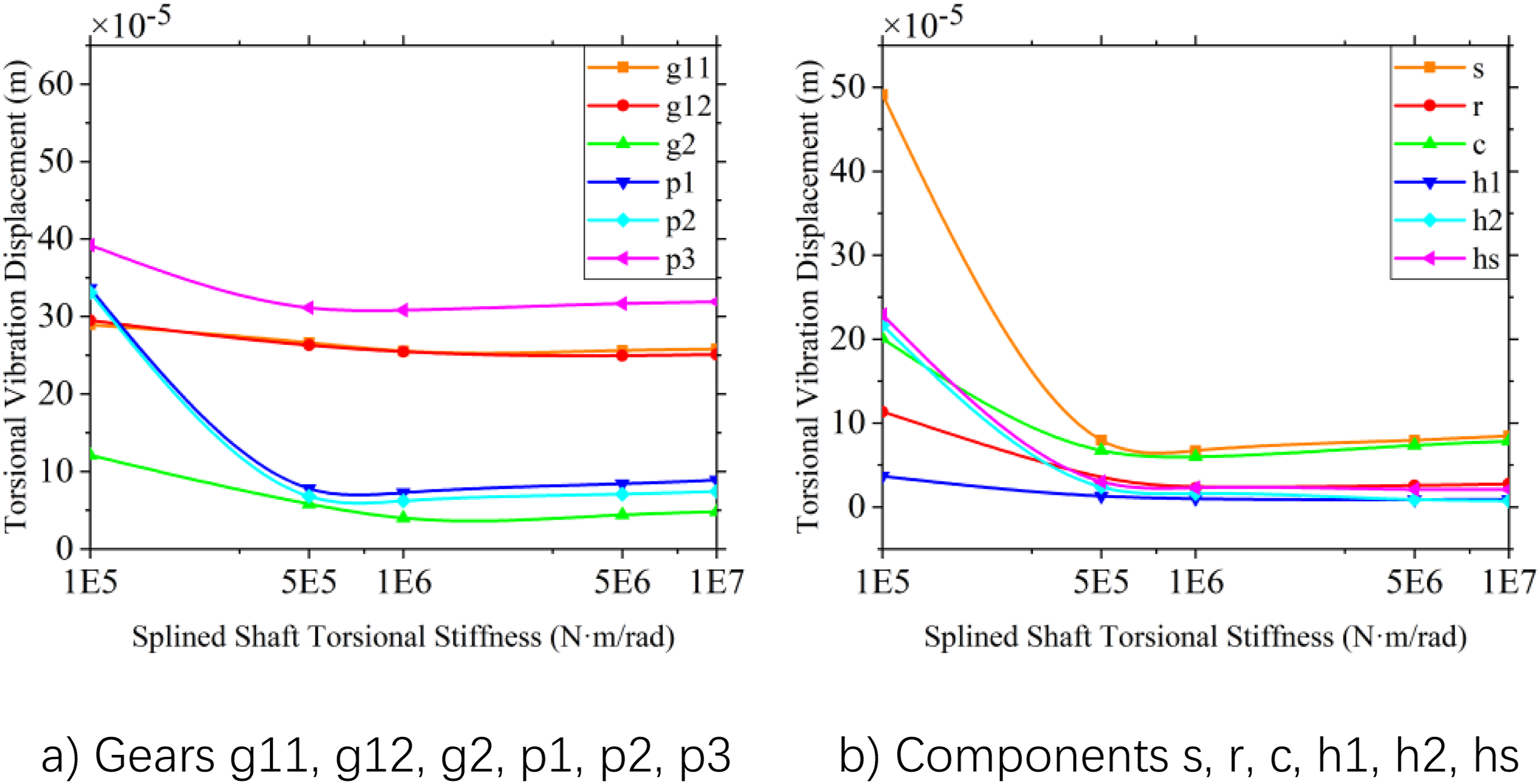
As can be seen from the figure, the torsional vibration responses of each component in the system generally decrease with the increase in the torsional stiffness of the spline shaft. When the torsional stiffness increases to a certain value, the peak-to-peak value of the torsional vibration response of each component increases, but the increase is limited. When the torsional stiffness of the spline shaft decreases to a certain value, the torsional vibration range of each component increases sharply. The analysis results indicate that the vibration response of the system can be adjusted and controlled to some extent by adjusting the torsional stiffness of the spline shaft.
From the perspective of inter-stage coupling, the spline shaft serves as a flexible connection between the parallel-shaft input stage and the planetary gear stage. Mesh stiffness fluctuations, error excitations, and torque fluctuations generated by the gear pairs in the input stage can be transmitted to the sun gear through the spline shaft, thereby further affecting the vibration responses of the planet gears, ring gear, and planet carrier. In addition, load fluctuations in the planetary gear stage can be fed back to the preceding stage through the spline connection. Therefore, the spline shaft stiffness directly governs vibration transmission and dynamic load distribution between the two transmission stages.
When the spline shaft torsional stiffness is low, the relative torsional deformation between the two stages increases, and torque fluctuations from the input stage tend to accumulate and be amplified at the spline connection, resulting in a significant increase in the system torsional vibration responses. As the torsional stiffness increases to an appropriate range, the relative deformation at the connection decreases, inter-stage torque transmission becomes more stable, and the system vibration responses are reduced. However, excessive torsional stiffness weakens the flexible buffering effect of the spline connection, allowing dynamic excitation from the preceding stage to be transmitted more directly to the planetary gear stage and causing the responses of some components to increase again. This indicates that the spline shaft torsional stiffness has a reasonable matching range, and its fundamental function is to regulate the dynamic coupling strength between the parallel-shaft stage and the planetary gear stage.
Mechanism analysis of vibration responses
The above results show that different excitation parameters affect the vibration responses of the system to different degrees, mainly because their physical action paths are different. Gear-pair mesh stiffness primarily affects the relative elastic deformation along the line of action and the transmission of dynamic mesh forces. Increasing the mesh stiffness reduces the torsional vibration responses of most rotating components, but may also enhance the transmission of mesh force fluctuations to the support structure, ring gear, and planet carrier, thereby increasing the lateral vibration responses of some components. Therefore, mesh stiffness has a directionally coupled effect on system vibration rather than acting as a simple vibration-reduction parameter.
Equivalent error significantly affects the system torsional vibration because tooth form, tooth profile, and pitch errors act as periodic displacement excitations when projected onto the line of action. These excitations directly change the relative mesh displacement of gear pairs and cause fluctuations in dynamic mesh forces. They can be transmitted through the input stage, spline connection, and planetary gear stage, leading to a synchronous increase in the torsional vibration responses of multiple components. By contrast, eccentricity error mainly acts as a periodic radial excitation, making the lateral vibration responses of the sun gear and planet gears more sensitive.
Support stiffness and spline shaft torsional stiffness influence the system responses mainly by changing the flexibility distribution and vibration transmission paths. Changes in support stiffness alter the vibration energy distribution between the input stage and the planetary gear stage, resulting in different response trends among components. As a flexible connection between the two stages, a spline shaft with insufficient torsional stiffness may amplify the relative torsional deformation, whereas excessive torsional stiffness may reduce the buffering effect of the connection. These results suggest that the coupling effects of error excitation, mesh stiffness, connection stiffness, and support boundary conditions should be comprehensively considered in subsequent parameter design.
Investigation of system vibration response under different rotational speed conditions
Effect of time-varying mesh stiffness on system vibration response under different rotational speed conditions
Keeping other parameters unchanged, the rotational speeds of the two input pinions are set to Variation curve of peak-to-peak value of torsional vibration displacement with mesh stiffness at different speeds.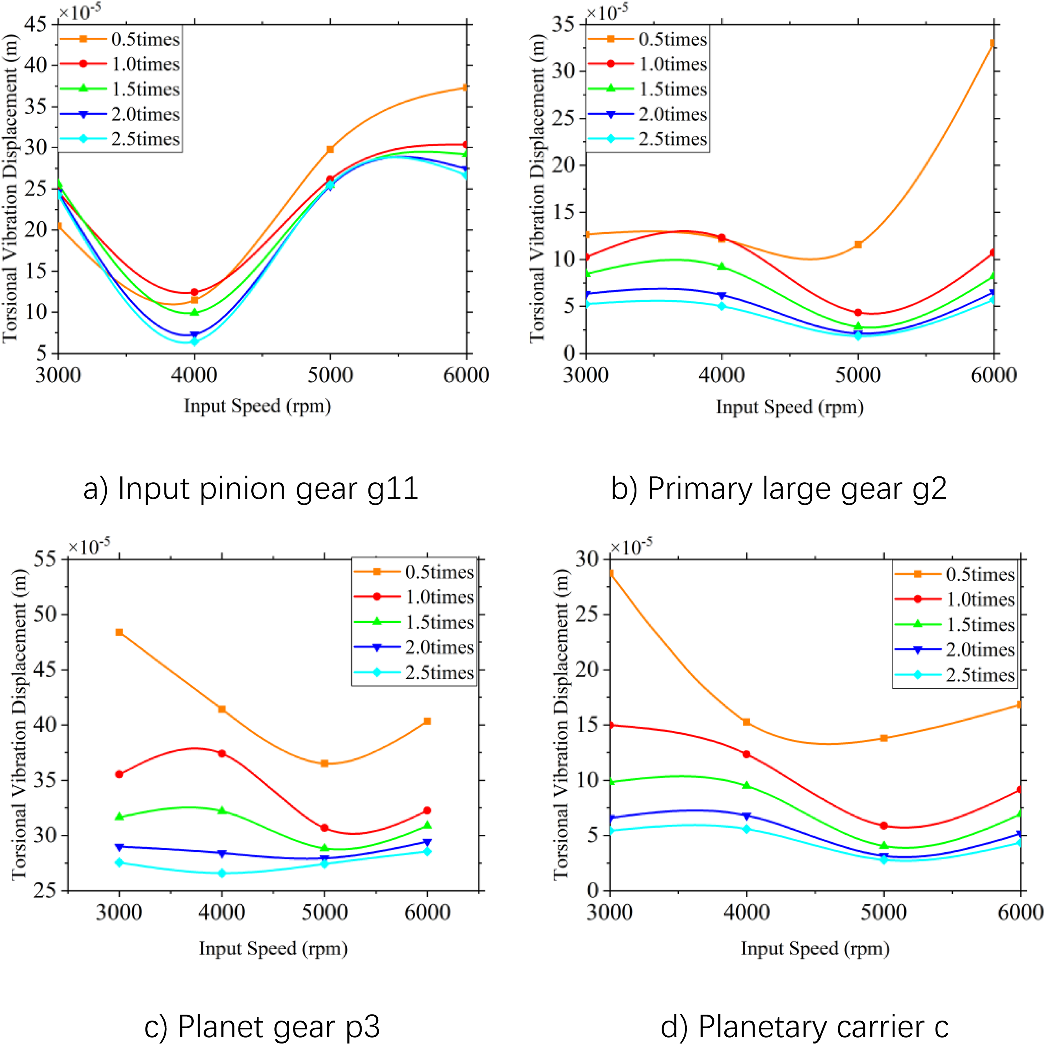
As can be seen from the figure, under different input speeds, the input pinion in the system operates in a relatively low-speed range. The peak-to-peak value of the torsional vibration displacement is low when the mesh stiffness is
Effect of equivalent error on system vibration response under different rotational speed conditions
To further study the influence of equivalent error excitation on the vibration response of the system under different speed conditions, the rotational speeds of the two input pinions are set to 5000 rpm, 6000 rpm, 7000 rpm, and 8000 rpm, respectively, and the equivalent errors of each mesh pair in the system are set to 0 μm, 50 μm, 100 μm, 150 μm, and 200 μm. The synchronous variation curves of the torsional vibration displacement responses of input pinion g11, primary gear g2, planet gear p3, and planet carrier C with the input speed and equivalent error are obtained, as shown in Figure 19. Variation curve of peak-to-peak value of torsional vibration displacement with equivalent error at different speeds.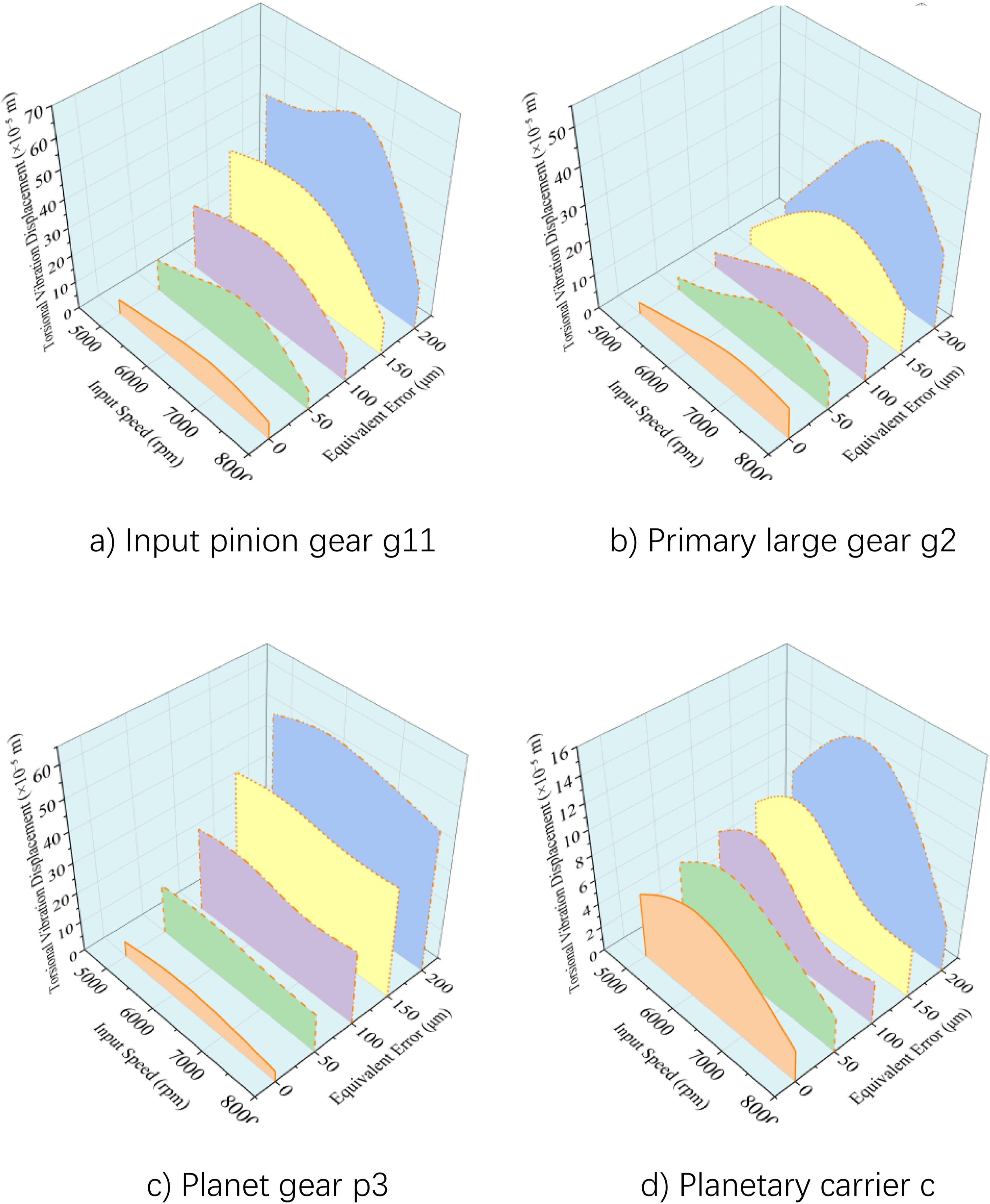
As can be seen from Figure 19, the peak-to-peak values of the torsional vibration displacement responses of the main components in the system increase with the increase in equivalent error under different speed conditions. This verifies the results obtained in the previous section regarding the influence of equivalent error excitation on the vibration responses of the system components. Under different design speeds, the torsional vibration displacement range of the gear system can be reduced by improving the manufacturing accuracy of gears and reducing the gear tooth profile and pitch errors.
Investigation of system vibration response under different load conditions
Effect of time-varying engagement stiffness on system vibration response under different load conditions
Other parameters are kept constant, and the load torques are set at 5000 N·m, 6000 N·m, 7000 N·m, and 8000 N·m. The mesh stiffness of each meshing pair in the system is 0.1 times, 0.5 times, 1.0 times, 1.5 times, and 2.0 times that of the steady-state working condition. The synchronous curves of torsional vibration displacement responses of input pinion g11, primary gear g2, planet gear p3, and planet carrier C with load torque and mesh stiffness are obtained, as shown in Figure 20. Variation curve of peak-to-peak value of torsional vibration displacement with mesh stiffness under different loads.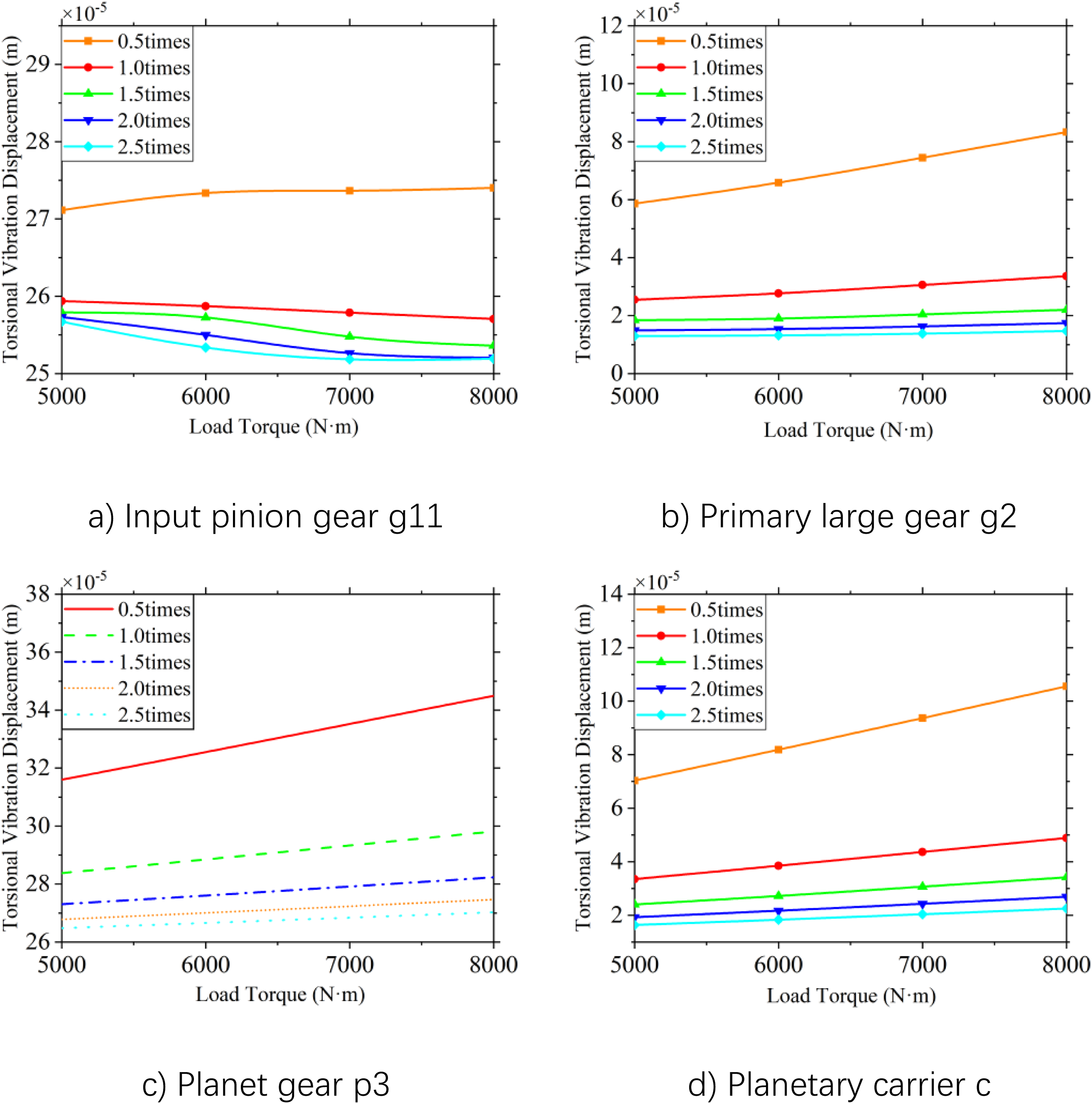
It can be seen from the figure that the overall amplitude of the torsional vibration displacement can be reduced by increasing the mesh stiffness of all gear pairs under different load torque conditions. When the mesh stiffness of input pinion g11 is equal to or greater than 1.0 times the value under the steady-state operating condition, the peak-to-peak value of the torsional vibration displacement decreases with the increase in load torque. When the mesh stiffness is 0.5 times the value under the steady-state operating condition, the peak-to-peak variation trend of the torsional vibration displacement is the same as that of other components; that is, the range of the torsional vibration displacement increases with the increase in load torque. When designing the transmission system, the fluctuation range of the torsional vibration displacement in the system can be adjusted by changing the mesh stiffness of the gear pairs according to the load state.
Effect of equivalent error on system vibration response under different load conditions
To further study the influence of equivalent error excitation on system vibration response under different load conditions. Set the load torques as 5000 N·m, 6000 N·m, 7000 N·m, and 8000 N·m, respectively, and the equivalent errors of each meshing pair of the system are 0 μm, 50 μm, 100 μm, 150 μm, and 200 μm. The synchronous variation curves of the torsional vibration displacement responses of input pinion g11, primary gear g2, planet gear p3, and planet carrier C with the load torque and mesh stiffness are obtained, as shown in Figure 21. Variation curve of peak-to-peak value of torsional vibration displacement with equivalent error under different loads.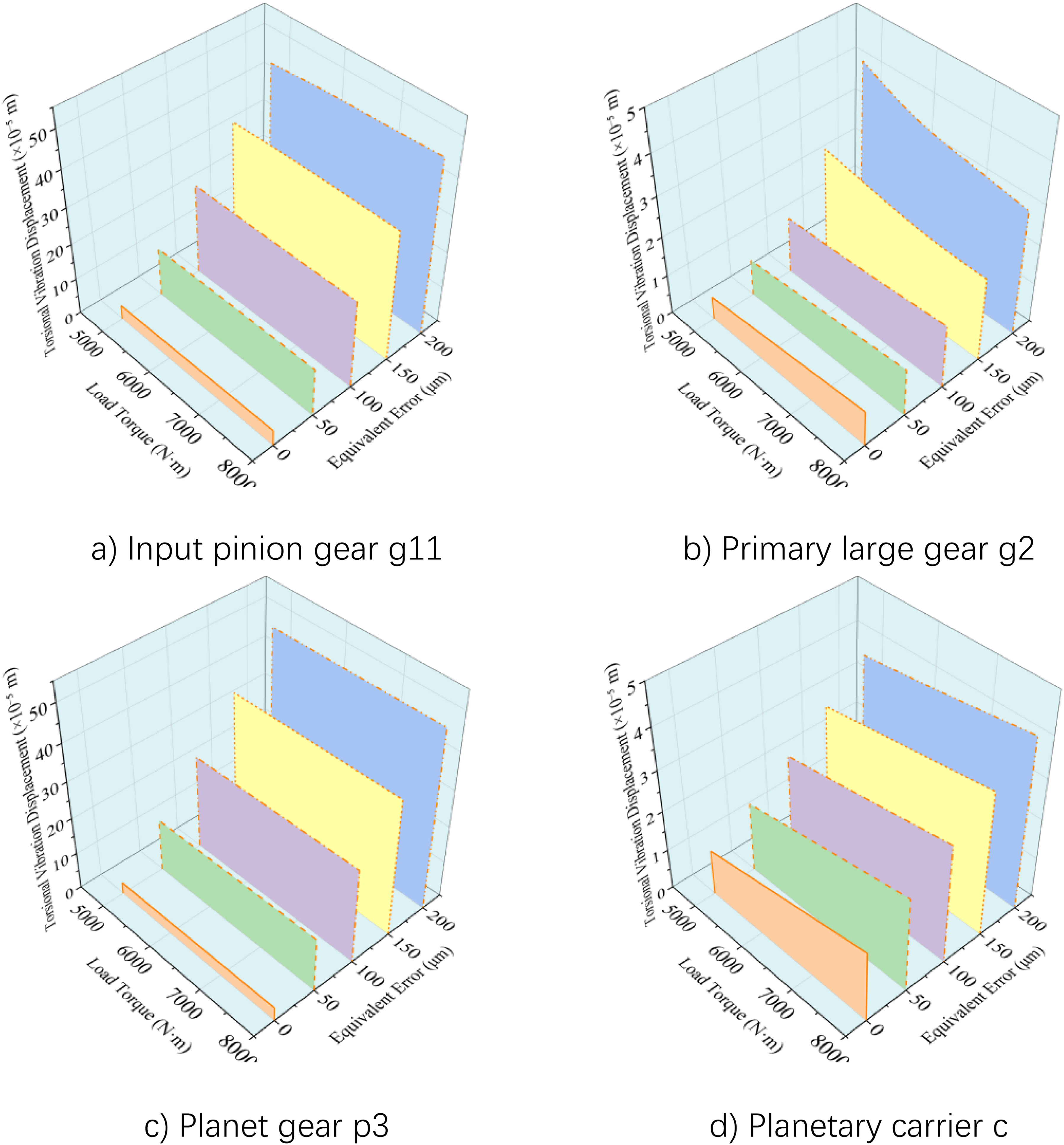
It can be seen from the figure that the increase in equivalent error increases the overall amplitude of the torsional vibration displacement of the system components under different load conditions. When designing the transmission system, the fluctuation range of the torsional vibration displacement in the system can be reduced by reducing the tooth profile and pitch errors under different load conditions.
Conclusion
In this study, a coupled dynamic model of a dual-input parallel-shaft planetary gear transmission system is established by considering the time-varying mesh stiffness of gear pairs, spline-pair mesh stiffness, equivalent error, backlash, support stiffness, and spline shaft torsional stiffness. The vibration responses of the system under steady-state operating conditions, different input speeds, and load conditions are analyzed. The mesh stiffness of the sun gear–planet gear pair is verified by comparing the potential energy method with the finite element method. The relative errors of the mean mesh stiffness and single-tooth mesh stiffness are
The results show that input speed, acceleration, and load have limited effects on the mean mesh stiffness of gear pairs, but they affect the system vibration responses by changing the mesh excitation period, contact state, and load transmission path. Increasing the mesh stiffness of gear pairs reduces the peak-to-peak values of the torsional vibration displacement of most components, but may enhance the lateral vibration responses of the sun gear, ring gear, and planet carrier. This suggests that increasing mesh stiffness does not necessarily reduce the overall vibration level of the system. Equivalent errors, including tooth form, tooth profile, and pitch errors, exert a more consistent amplification effect on system torsional vibration under different input speeds and load conditions, and are therefore key excitation factors for this type of transmission system.
The planetary-stage components exhibit non-uniform vibration characteristics. Among the three planet gears, planet gear p3 shows higher torsional vibration responses under various parameter and operating-condition changes. This phenomenon is related to the coupling effects among the planet gear installation phase, internal and external mesh phases, and error excitation phase, which cause different dynamic responses along different power-splitting paths. Therefore, the vibration evaluation and optimization design of dual-input power confluence and planetary-stage power-splitting transmission systems should consider not only the average response of the planet gears, but also local components with high vibration responses.
Overall, the low-vibration design of dual-input parallel-shaft planetary gear transmission systems should not depend solely on increasing mesh stiffness. Equivalent errors, such as tooth form, tooth profile, and pitch errors, should be preferentially controlled, and the spline shaft torsional stiffness and support stiffness should be jointly optimized. For helicopter gearboxes, gear micro-error control, connection stiffness matching, and support parameter design jointly determine the system vibration level. These results provide a theoretical basis for subsequent tooth profile modification and low-vibration optimization design.
Footnotes
Declaration of conflicting interests
The authors received no financial support for the research, authorship, and/or publication of this article.
Funding
The authors disclosed receipt of the following financial support for the research, authorship, and/or publication of this article: The Harbin Key Industrial Science and Technology Research project: Research and Engineering Application of Key Technologies for Aviation Gear Drives under Dry Running Conditions. The Heilongjiang Province Key Research and Development Program (Grant No. 2025ZX01A12).