



Abstract
The use of double-sheet enclosures with an intermediate non-ventilated air cavity guarantees a higher airborne sound insulation. The insulation advantages depend on air tightness and the placement of sound absorbing material in the air cavity. The lightweight ventilated façade is a system constructed by the addition of an external light cladding on a heavy single wall to establish an intermediate air cavity. This air cavity can be ventilated under controlled cooling effects, because of Sun’s radiation, and to reduce the risk of dampness caused by rainwater. Owing to this ventilation, acoustic insulation of the lightweight ventilated façade could be less effective. However, some authors indicate that air cavity moderate ventilation does not necessarily lead to a significant reduction in the airborne sound insulation. The authors previously verified this situation in a real building where the existing façade of masonry walls was transformed into a lightweight ventilated façade. The preliminary results indicate the acoustic benefits can be compatible with the hygrothermal benefits derived from controlled ventilation. This article presents the next step, the evaluation of the lightweight ventilated façade acoustic performance under laboratory conditions to revalidate the previous results and refining aspects as the air cavity thickness or the state of openings ventilation. The main results obtained indicate that the airborne sound insulation in laboratory is aligned with the previous results in a real building. Air cavity thickness from 110 to 175 mm and ventilation openings from 0% to 3.84% of the façade area does not lead to a significant reduction in the airborne sound insulation.
Keywords
Introduction
The sound reduction behaviour in a single wall faced with airborne outdoor noise follows, in a rough approximation, the mass law

where R = diffuse field transmission loss (dB); f = frequency (Hz); ms = surface mass density of the cladding board material (kg/m2 or lbr/ft 2 ); KR = numerical constant = 47.3 dB in metric units and 33.5 dB in FP units.
According to the mass law, when a wall with a certain surface mass density ms (kg/m2) and a certain level of sound insulation (TL) doubles its weight, its value of TL does not double and the increase in sound insulation level does not exceed 6 dB at the starting point. Therefore, in practical and economic terms, it is not functional to increase the wall weight when looking for better sound insulation.
The sound insulation values of a single wall can be more efficiently improved with additional unlinked layers of material with a different thickness and mechanical rigidity, according to the mass–spring–mass model. One of the most commonly used layers is the unventilated intermediate air cavity, due to as much to its low cost as to its light weight. A progressive increase in thickness of this intermediate air cavity could represent a qualitative and quantitative increase in sound insulation performance.1,2 Based on research and trials by various authors, including Fahy, 2 Hongisto, 3 Dijckmans et al., 4 Warnock and Quirt, 5 Frutos Vázquez et al., 6 Halliwell et al. 7 and Blasco et al., 8 the acoustic performance of any double walls is improved by the interposition of an air cavity, if it contains sound absorbing material.
The lightweight ventilated façade (LVF) is a construction subtype of what is known as the ventilated façade. The LVF consists of a double envelope with a heavy inner wall, usually masonry, and lightweight exterior cladding, demarcating an intermediate air cavity between the two sheets. The system is commonly used in new constructions and nowadays to refurbish ancient building façades. The intermediate air cavity collaborates to improve thermal conditions and water tightness. Adequate controlled ventilation of this intermediate air chamber can favour a beneficial and efficient hygrothermal control on the LVF. The ventilation openings of this intermediate air cavity can be produced either by the coupling joints of the cladding boards that form the outer sheet (depending on the board formats that are used), or can be inserted on the upper and lower limits of the intermediate air cavity. Ventilation openings are usually distributed equally to guarantee adequate, uniform, and constant ventilation. 9
European construction standards usually establish minimum regulatory requirements for the ventilation of intermediate air cavities in façades to assure a good hygrothermal control. The Spanish Technical Building Code Documents indicates that intermediate air cavities used in double façades should meet the DB HS 1 specifications: 10 ‘. . . ventilation openings with a total effective area of at least 120 cm 2 must be provided for every 10 m 2 of façade between floors (if we take an standard height between floors slabs of 3 m, is equivalent to a surface openings of 3600 mm 2 /m, 0.12% of total surface), distributed 50% between the top and bottom Grid openings, mortarless sores, open joints in discontinuous coatings having a width greater than 5 mm or other solution that produce the same effect can be used as openings’.
The LVF has also added airborne sound insulation potential compared to a single envelope façade. The continuity of the intermediate air cavity decreases flanking transmission and even reduces some vibro-acoustic transmission that may occur inside the cavity, as long as acoustic absorbent material is used. 1 But the question is whether the ventilation openings of LVF can reduce or even eliminate the added airborne sound insulation potential. Some authors consider a ventilated air cavity does not necessarily decrease the sound reduction acoustic performance of double walls. 11 In a first measurement campaign carried out ‘in situ’ on a real façade of an existing building where a LVF had been installed as refurbishing solution for a previous masonry façade, 12 it was found that sound insulation against airborne noise was not dramatically affected by the moderate ventilation proposed in the European Construction Codes for hygrothermal control purposes. This aspect should be considered in the renovation of existing building facades.
The contribution of the LVF to improve the level of acoustic insulation in each case appears to depend, in principle, on the thickness of the intermediate air cavity, its absorbent acoustic characteristics, and the layout and extension of ventilation openings. CEC 13 considers ‘. . .when a facade has a chamber with an effective ventilation area between 500 mm 2 ⩽ Aeffective < 1500 mm 2 , 1 dB must be subtracted from the value of RA and RAtr. When a facade has a chamber with an effective ventilation area between 1500 mm 2 ⩽ Aeffective < 3600 mm 2 , 2 dB must be subtracted from the value of RA and RAtr.’
To check this assumption and define its scope quantitatively, this research assesses the influence of ventilation variables on the airborne sound insulation of a LVF, bearing in mind:
The thickness of the intermediate air cavity.
The area of ventilation openings.
The pattern and layout of ventilation openings.
Methods
The method of this research was to assess the level of airborne sound insulation of the LVF, through a laboratory test. The LVF construction system used for the test was the Aquapanel commercial standard system produced by Knauf (Figure 1). This system was chosen for its accessibility and versatility.

Isometrics of the Aquapanel LVF system, with a description of the sub-structure and fastening elements.
The system’s lightweight outer sheet is composed of 1.20 × 2.40 m boards of cement mortar reinforced with glass fibres (CB) with a thickness of 12.5 mm. Joints between boards can be open or sealed. The thickness of the intermediate air cavity is constant and is determined by the width of the metal brackets that are anchored to the base wall. These brackets hold the cantilevered metal profiles of the sub-structure that holds the CB of the lightweight outer sheet. The inside of the intermediate air cavity also includes a layer of sound absorbing material, in this case mineral wool panel (Figure 1).
Mathematical model of reference
The mathematical expressions used to obtain and calculate acoustic insulation level results are established by current regulations for acoustic measurements in laboratory tests. 15 The conversion of a single and heavy wall façade to an LVF by adding an external cladding of CB was evaluated in terms of sound reduction index R (dB).
In the frequencies evaluation of the acoustic behaviour of double wall façades, certain sound frequencies were observed to produce a sharp drop in the level of acoustic insulation. The frequencies that led to a sharp reduction are associated with coincidence frequencies (see Table 1).
Results of the estimate coincidence frequency (fc).

The natural (or resonance) frequency of the set of walls refers to a system formed by two masses m1 and m2 (inside sheet and outside sheet) joined by a spring (intermediate air cavity) of rigidity K.
This mass–spring–mass system, with joint vibrating capacity, has its own proper resonance frequency (fmsm), which is determined by the following equation

where ρS = mass per area unit (surface density in kg/m2) of each sheet; 60 = constant for an empty air cavity (with no sound absorbing material); Lz = thickness of the cavity in metres (m).
If the intermediate air cavity is fully or partially filled with sound absorbing material, the proper frequency can be determined by the following equation

In this case,
In a fully or partially filled air cavity, this value divides the elasticity module E of the sound absorbing material by its thickness. In a partially filled cavity with sound absorbing material, the natural frequency of the sound absorbing material can be determined (Equation (2)), but the effective thickness of the cavity is calculated by the following equation

where Lz,eff = is the effective depth of the cavity in metres (m); Lz = depth of the cavity in metres (m); d = thickness of the porous material in metres (m); ɸ = porosity coefficient of the absorbent material (value between 0 and 1).
Table 2 summarizes the resonance frequency of double systems fmsm obtained for the laboratory model.
Results of the estimated resonance frequency of double system (fmsm).

LARGE: Laboratory for Acoustic Research on Glass and Large Envelopes; LVF: lightweight ventilated façade.
Description and development of the laboratory tests
The laboratory test was carried out in the Laboratory for Acoustic Research on Glass and Large Envelopes (LARGE, http://blascobvba.blogspot.com/), Ghent, Belgium, in April 2012. This laboratory has a reverberation chamber with a surface area of 57.89 m² and a volume of 280.75 m³. This chamber is preliminary divided with a base wall, a prefabricated concrete single wall of 200 mm thickness with a surface density of 500 kg/m2 designed for testing by LARGE with an overall sound reduction value Rw = 43 dB. Their sound reduction index R, as seen in Figures 2–4, is quite constant frequency-by-frequency because of the specific design of this wall oriented to facilitate the test of glass and large envelopes.
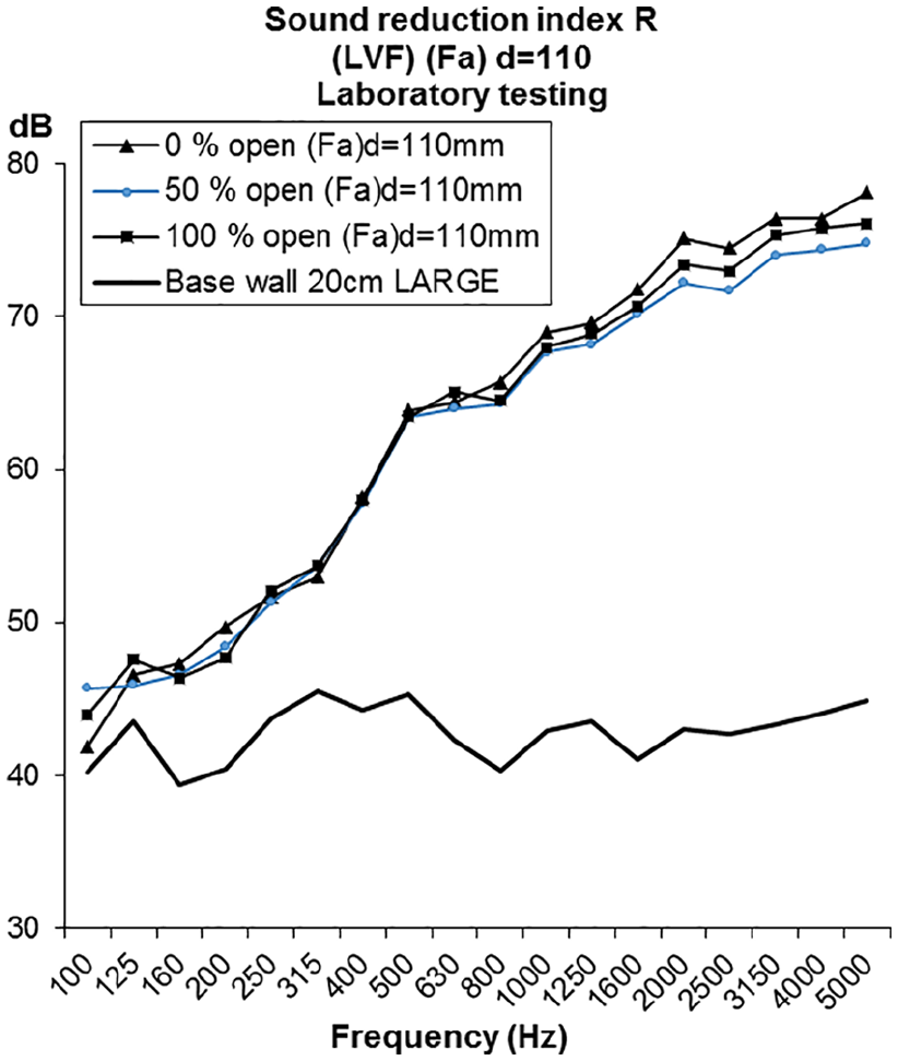
Superimposed graph of the sound reduction index R (dB) in the case of 119-mm air cavity thickness for different states of opening.
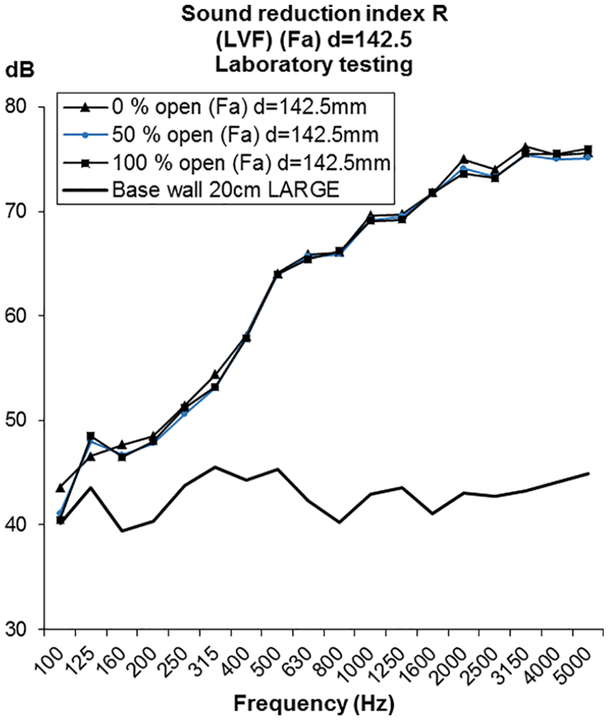
Superimposed graph of the sound reduction index R (dB) in the case of 142.5-mm air cavity thickness for different states of opening.

Superimposed graph of the sound reduction index R (dB) in the case of 175-mm air cavity thickness for different states of opening.
Description of the prototype tested in the laboratory
In this case, the LVF system added to the base wall was comprised of a sub-structure of metal profiles, a mineral wool panels of 60 mm thickness and 40 kg/m2 density inserted between the metal profiles and a cladding of CB panels (Figure 5). The dimension of the tested area was 4.60 m wide × 4.30 m high. The LVF was anchored around its perimeter to the ground and ceiling of the reverberation chamber.

Vertical section of the LVF model, tested in LARGE laboratory. The air cavity thickness is indicated: d = 110 mm, d = 142.5 mm and d = 175 mm; where, A = LVF, B = lightweight cladding system formed by the sub-structure and a layer of sound absorbing material, in this case a semi-rigid panel of mineral wool of 60 mm thickness, and a CB panel (these elements comprise the intermediate ventilated air cavity) and C = base wall, reinforced concrete wall of 200 mm thickness.
The main goal in this case was to evaluate the sound reduction performance of the LVF by trying out different openings in the cladding of CB panels and using several air cavity depths (110, 142.5 and 175 mm) to observe how this parameter influenced the acoustic behaviour of LVF. As the air cavity is partially filled with a mineral wool panel of 60 mm thickness, the effective thickness is reduced (50, 82.5 and 115 mm) but in the rank of building regulations. 10
In this test, two linear ventilation openings (air gap) were made in the upper and lower area of the LVF, each measuring 100 mm × 3800 mm (Figure 5), on the outer sheet of CB panels. This ventilation openings are 4.65% of total surface, quite bigger than minimum for hygrothermal purposes. The gradual opening of the intermediate air cavity was considered at three states of ventilation: 100%, 50% and 0% of the total opening surfaces (Figures 6 and 7), equivalent to 3.84%, 1.92% and 0% of total wall area.

Diagrams of front and section view of LVF. Layout of upper and lower ventilation openings, indicating the average of ventilated surface. The letters in the diagrams correspond to: A = the assembly of the LVF system, B = the lightweight system and C = the base wall.

Photo inside the LARGE reverberation chamber, taken during the airborne sound insulation tests. The upper and lower ventilation openings can be distinguished.
Table 3 characterizes the thickness, surface density and density values of each layer of the LVF prototype to evaluate the acoustic behaviour.
Technical characteristics of the LVF prototype in the laboratory test.

CB: cement board; LVF: lightweight ventilated façade.
Results and analysis of the laboratory test
Figures 2–4 show the values of the sound reduction index R obtained from measurements in each frequency for the different air cavity thicknesses (110, 142.5 and 175 mm) in the LFV prototype. The graphs correspond to the three states of ventilation opening in the intermediate air cavity: 0%, 50% and 100%. In all the measurements made in the laboratory test, a clear increase in the sound reduction index R by frequencies can be observed for the LVF system in comparison to the previous R values of the reinforced concrete base wall (continuous black line). However, there was no significant variation in the R value due to different states of ventilation openings of the outer sheet cladding. This result is significant, because in this case the ventilation openings were located on the same LFV plane and within a reverberation field. There was only a 2-dB reduction in airborne sound insulation values for the largest air cavity when the state of ventilation openings is maximum (100%) within the tested range (Table 4). These results are probably an indication of the impact represented by the location of fibrous materials of considerable relative thickness (60 mm) in this ventilated air cavity (175 mm).
Rw (C, Ctr) results obtained from the proposed three states of ventilation opening and the three air cavity thickness.

LVF: lightweight ventilated façade.
Figures 8–10 show the values of the sound reduction index R obtained in measurements carried out for 0%, 50% and 100% openings. Graphs corresponding to the different depths of the air cavity of the prototype (110, 142.5 and 175 mm) are superimposed for comparison.

Superimposed graph of the sound reduction index R (dB) for the same state of opening (0%) considering the three air cavity thickness (110, 142.5 and 175 mm).

Superimposed graph of the sound reduction index R (dB), for the same state of opening (50%) considering the three air cavity thickness (110, 142.5 and 175 mm).

Superimposed graph of the sound reduction index R (dB), for the same state of opening (100%) considering the three air cavity thickness (110, 142.5 and 175 mm).
Figures 8–10 indicate that the variation in the thickness of the intermediate air cavity in the rank of commercial solutions (110, 142.5 and 175 mm), does not significantly influence the airborne sound insulation according to index R values for the three states of ventilation openings of the intermediate air cavity (0%, 50% and 100%). It can be checked in the graphs the position of the estimate coincidence frequencies (see red arrows). It can be concluded that when the states of opening ventilations increase, the influence of base wall performance becomes more clear.
Conclusion
The results achieved to date appear to support the initial hypothesis that LVF can considerably increase the airborne sound insulation of a previous single heavy façade, and this aspect does not appear to lessen according to the air cavity thickness, the layout of ventilation openings or their degree of opening, always in the rank of dimensions established for hygrothermal purposes.
When the state of openings ventilation of the intermediate air cavity is modified this variation does not generally, significantly reduce improvements in airborne sound insulation of LVF.
The situation of openings for ventilation in the same plane of the lightweight cladding system does not necessarily decreases the acoustic performance of the LVF, compared to a non-ventilated intermediate air cavity.
The results of the laboratory test are aligned with the previous results of field test: 12 the addition of a lightweight cladding system over a heavy masonry wall, with an intermediate ventilated air cavity, to achieve a LVF, led to considerable improvement of airborne sound insulation, in the rank of standard dimensions of commercial solutions. It is suggested to continue this research to aim for the specifications of building regulations to consider the benefits, both acoustic and hygrothermal, of LVF when applied to improve performance of heavy masonry wall façades.
Footnotes
Acknowledgements
The authors acknowledge the people and businesses that performed the measurement tests and made this research possible: Departament de Tecnologia de la Arquitectura, Universitat Politècnica de Catalunya (UPC); Mr Arnaud Cariola and Mr Danny Decaluwaert, Knauf Belgium; Dr André De Herde, Départament d’Architecture et Climat, Université Catholique de Louvain La-Neuve; Dr Marcelo Blasco, LARGE (Laboratory for Acoustic Research on Glass and Large Envelopes), Ghent, Belgium.
Authors’ Note
Andrea Niampira is now affiliated with Universidad Pontificia Bolivariana- Sede Montería, Colombia.
Declaration of conflicting interests
The author(s) declared no potential conflicts of interest with respect to the research, authorship and/or publication of this article.
Funding
The author(s) received no financial support for the research, authorship and/or publication of this article.
