
Abstract
This study proposes sonic crystal green walls based on combined cylinder scatterers and vegetation. It has been known that the vegetation or greenery system is effective in dealing with environmental pollutants, while the cylinder scatterer arranged periodically, also known as a sonic crystal, is preferable owing to the capability of noise attenuation, light transmission, and air circulation simultaneously. Combining both components into a single noise abatement system is expected to provide acoustical and non-acoustical features for urban design, where such an approach maximizes the merit of each component. Moreover, the system is useful for advocating sustainability amid global warming issues. In this work, a numerical model is developed using finite element method (FEM), while experimental results are provided to validate the absorption and attenuation results. It is found that the sonic crystal can attain an attenuation of 13.5 dB around 1.6 kHz. Such a promising result is extended further to lower frequency under a specific configuration of scatterers corresponding to lattice distance and filling faction ratio parameters. Meanwhile, the vegetation can enhance overall attenuation at higher frequencies.
Introduction
In green infrastructures (GI), vegetation is one of the main elements that are capable of providing multiple functions and ecosystem services.1,2 The vertical greenery system (VGN), as a branch of the GI classification, has become attractive and relevant for green building and urban planning in order to deal with climate change challenges. 3 According to VGN nomenclature, the VGN can be divided into two main categories 4 : (1) green wall/living wall; (2) green façade. Numerous studies indicate that the benefits of thermal comfort, air quality, noise reduction, hydrology, and biodiversity are evident from the use of vegetation or greenery systems apart from aesthetic improvement. In addition, this system becomes more relevant in the case of multi-story buildings where the vegetation system can be vastly applied to most of the bare vertical area.
The use of vegetation as a countermeasure to urban noise has been proposed in the last twentieth century. Vegetation belts are commonly used to obtain noise shielding.5 –7 Recently, vertical and roof greening systems have been an emerging field where noise reduction is also expected to be present.4,8,9 Noise attenuation of vegetation exists due to absorption, diffusion, and scattering by leaves and stalks of the vegetation. 10 The mechanical vibration is also involved in noise attenuation,11,12 while the use of lightweight and porous substrates can dramatically increase the absorption capacity of the plant. 13 Absorption and attenuation of vegetation show low to moderate performance ranging from the absorption of 0.2 to 0.5 14 and the attenuation of around 10 dB. 15 Hence, the vegetation has been known to have poor noise attenuation, especially below 1.000 Hz for noise attenuation purposes, but it is effective for mid and high frequencies with properly selected properties.15,16 Meanwhile, noise attenuation performance at low-medium frequency is important because traffic noise has spectral components ranging from 200 to 2500 Hz depending on the weight of the vehicle. 17 Some efforts to extend the acoustic performance of vegetation have also been made by embedding resonator unit cells in the vegetation under periodic arrangement18,19; such an approach is known as metaporous scheme.20,21 It was found that the sound absorption of vegetation was successfully enhanced at 700–1150 Hz. However, the associated structures are challenging to be realized in real implementations.
The set of solid scatterers arranged periodically with a specific distance between them, known as lattice distance, is referred to as sonic crystals (SC). The system has received much more attention from the acoustical community owing to the ability to act as stop-band filters in the audible frequency range, thanks to the existence of bandgaps. 22 Hence, placing SC between sound sources and receivers can provide attenuation, while allowing light to pass and the free flow of air through the gaps between the scatterers. Such a benefit is not found in traditional sound screens, concrete walls, or solid barriers. Hence, sonic crystals have been implemented as acoustic sound screens or sound barriers as an alternative to traditional ones.23 –26 Some studies and developments on the scatterer shapes and orientation have been carried out to adjust further the band gap characteristics.27 –29 It should be noted that the scatterer dimension and the lattice distance must be comparable in size with the wavelength because the effect of the bandgap arises from diffraction. The use of SC in the greenery system was experimentally demonstrated in the green belt cases or forests where a mass of trees was arranged in a periodic lattice. 30 It is found that an attenuation enhancement is present at frequencies below 500 Hz from such an approach. However, using a set of trees to reduce noise is not always applicable in urban design due to space availability and safety. Despite this, the SC is attractive as the system can perform acoustic attenuation in a wider frequency range that is determined by lattice distance and scatterer diameters.23,24,31
Noise mitigation in the urban environment is becoming important due to the expanding urban areas, mobility trends, and new infrastructures. 32 Noise attenuation capability is critical, but other disciplines that are related to urban landscape, environment, economics, sociology, ecology, etc., also need to be considered. Hence, a new approach to finding a viable solution is necessary. From this point of view, some efforts have been devoted, for example, using vegetation on the barrier surface can lead to 7 dB additional insertion loss compared to a bare plane noise barrier, as reported by Haan and Hong. 33 This effort simultaneously embraces noise attenuation and landscape aspects, as the vegetation can provide a visual impression of landscape quality. 34 Recently, the SC has been used as a noise barrier to allow urban areas to meet the recommended noise levels amid increasing traffic noise and the presence of multipurpose area or sensitive area in a district. 35 The use of SC in this case can allow air circulation and noise attenuation.
This study aims to investigate attenuation characteristics of the combination of vegetation and cylinder scatterers what so-called sonic crystal green walls by developing the system design, associated numerical models, and testing the transmission loss performance. The combination of vegetation and SC is hypothetically expected that each component to work on different targeted frequencies at low, mid, and high frequencies by which a wider attenuation bandwidth can be obtained. Meanwhile, the contribution of both attenuation mechanisms is also expected to enhance the total attenuation compared to that of each component employed independently. In specific, this study is devoted to address some key aspects of the design procedure of sonic crystal green walls: (1) model development for representing vegetation, sonic crystal, and a combination of both sub-systems using Finite Element Method (FEM); (2) How attenuation behavior of each sub-system determines overall attenuation or transmission loss; (3) How the parameters of each sub-system affect attenuation of each other over a particular attenuation frequency range. With that, it is expected that a reference model and a better understanding of the proposed system will be available for further development and practical implementations so that the system can be designed systematically to avoid a trial-error approach for practical purposes. Moreover, this effort to combine those elements into a single acoustical system simultaneously embraces acoustical and non-acoustical features, which is beneficial for noise mitigation in the urban environment.36 –38
Material and method
Sound screen system design
To realize the sonic crystal green wall system, climbing plants are used and combined with sonic crystal which is embedded into the plants in the sense of a multi-layer system, as shown in Figure 1. Hence, the proposed greenery system in this study is considered a continuous system pairing with the cylindrical scatterer unit of SC in the vertical direction. This suggests that the proposed system can function as an independent wall, barrier in an open space, or room divider, or it can be adopted for green walls and green façades for better noise attenuation performance.
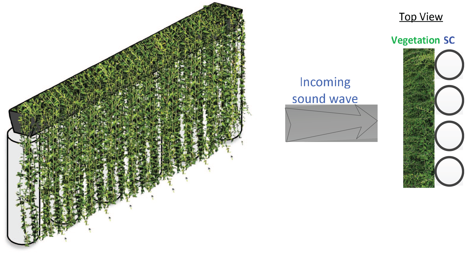
Schematic of proposed sonic crystal green walls.
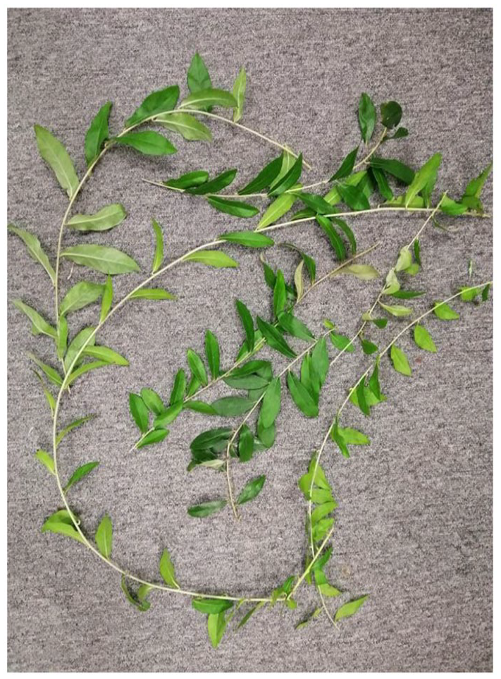
Lee Kuan Yew (Vernonia Elliptica DC) plants are employed in this study and illustrated in Figure 2. This plan is ideal for realizing our concept as the trunk can grow and propagate 0.5 m up to 3 m, while the plants are less maintenance-intensive so that they can last longer than other plants. This characteristic is beneficial for the greenery system. Apart from this, the soil can be situated at the lower part or top section so that most of the area is predominated by the foliage. This can help simplify the problem of absorption and transmission mechanisms, which are attributed to absorption, diffusion, and scattering by the leave and SC.
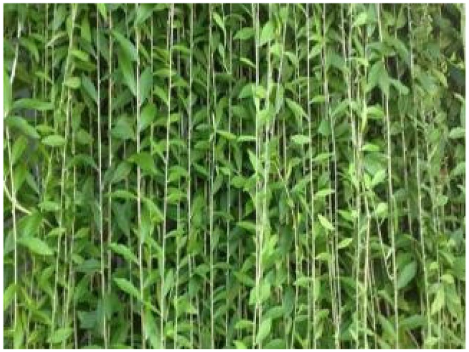
Lee Kuan Yew (LKY) plant used in this study.
Numerical model
2D model FEM
The modeling and simulations were performed in COMSOL Multiphysics 5.6. All models are discretized by triangle elements with maximum dimensions of around 0.014 m, which relates to the minimum wavelength divided by six with a maximum frequency of 4000 Hz as shown in Figure 3. Meanwhile, structured rectangular elements are employed for the perfectly matched layer (PML) domains which are designated as anechoic termination. All elements have dimensions well below

Schematic numerical model.
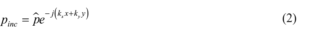
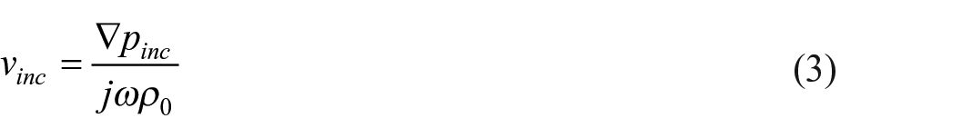
The incident sound power Winc is determined as follows,

with
with


with ko as acoustic wavenumber in air and
The total transmitted sound power Wtrans evaluated at the back surface of the system from where the transmission coefficient
From equation (6), the transmission loss of the system is then defined as
3D model of diffuse sound transmission loss
The diffuse sound transmission loss simulation was developed by assuming an ideal diffuse field on the source side and an ideal anechoic termination on the receiver side, representing the reverberation-anechoic setup measurement. A sum of
with
This room pressure

Schematic model of diffuse sound transmission: (a) model setup of diffuse sound TL, (b) implementation of 3D model to obtain diffuse sound transmission loss.
The diffuse transmission loss

where
with

where
Eigenvalue problem: Dispersion relation
The unit cell is shown in Figure 5. The boundaries of the cylinder scatterer are considered acoustically rigid, while the Floquet-Bloch boundary conditions are considered on the edges of the unit cell to represent the periodicity of the system as follows,

where
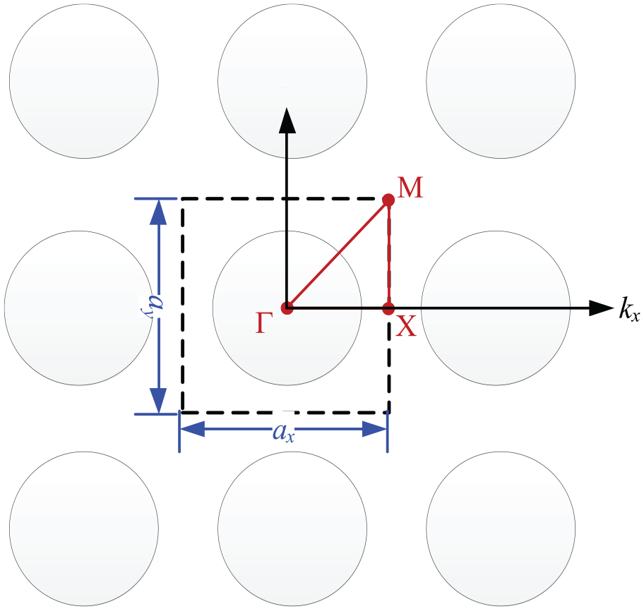
Single unit cell of an infinite sonic crystal system with periodic boundary conditions.
The resulting attenuation of a sonic crystal corresponds to band gap characteristics represented by the center frequency and bandwidth. The center frequency of periodic structure can be set according to Bragg’s law where the frequency is proportional to the ratio of sound speed

where
Non-acoustical parameters
Vegetations consist of air, stems, trunks, twigs, and leaves, resulting in a complex medium that needs to be modeled. In this study, the viscous losses and thermal dissipation of sound waves as they propagate through vegetation are modeled using an equivalent fluid model of porous acoustic. An empirical model proposed by Miki 40 is evident in providing a good prediction result for plant absorption cases, considering the studies carried out by Horoshenkov et al. 41 and D’Alessandro et al. 42 The details of this formulation can be obtained from Appendix 1.
Experimental setup
Vegetation sound absorption
The non-acoustical parameters of vegetation are obtained by direct and indirect approaches. The porosity and the structure factor as expressed in equation (A.1) and (A.2) by observing and characterizing the Lee Kuan Yew plant based on the foliage occupancy and the angle of leaves. Meanwhile, the fitting curves to experimental data using the Miki model are applicable for getting flow resistivity σ, tortuosity
Test sample for obtaining the Miki model parameters of the vegetation.
A schematic diagram of the measurement method is shown in Figure 7 where a square tube made of 10-mm acrylic was employed. The impedance tube design and the measurement of the absorption coefficient of the MPP were carried out according to ISO 10534-2. 43 This impedance tube has a mean difference of 0.04 points in sound absorption coefficient compared with that of commercialized circular impedance tubes. The speaker generated white noise, and it was considered a plane wave traveling in a square tube with a side length of 85 mm to cover a frequency of 125–1700 Hz. This plane wave condition was held because the wavelength of the wave at the highest frequency was longer than the lateral tube width to avoid cross-section modes. The microphones were swapped during the measurements. Two microphone spacing types were implemented to cover the low- and high-frequency ranges. The data from 125 to 500 Hz was gathered from a 30 cm microphone’s spacing. The other spacing of 6.5 cm was utilized to collect data from 300 to 1700 Hz. The data of the overlapped frequency range were averaged to obtain the overall absorption coefficient curves.
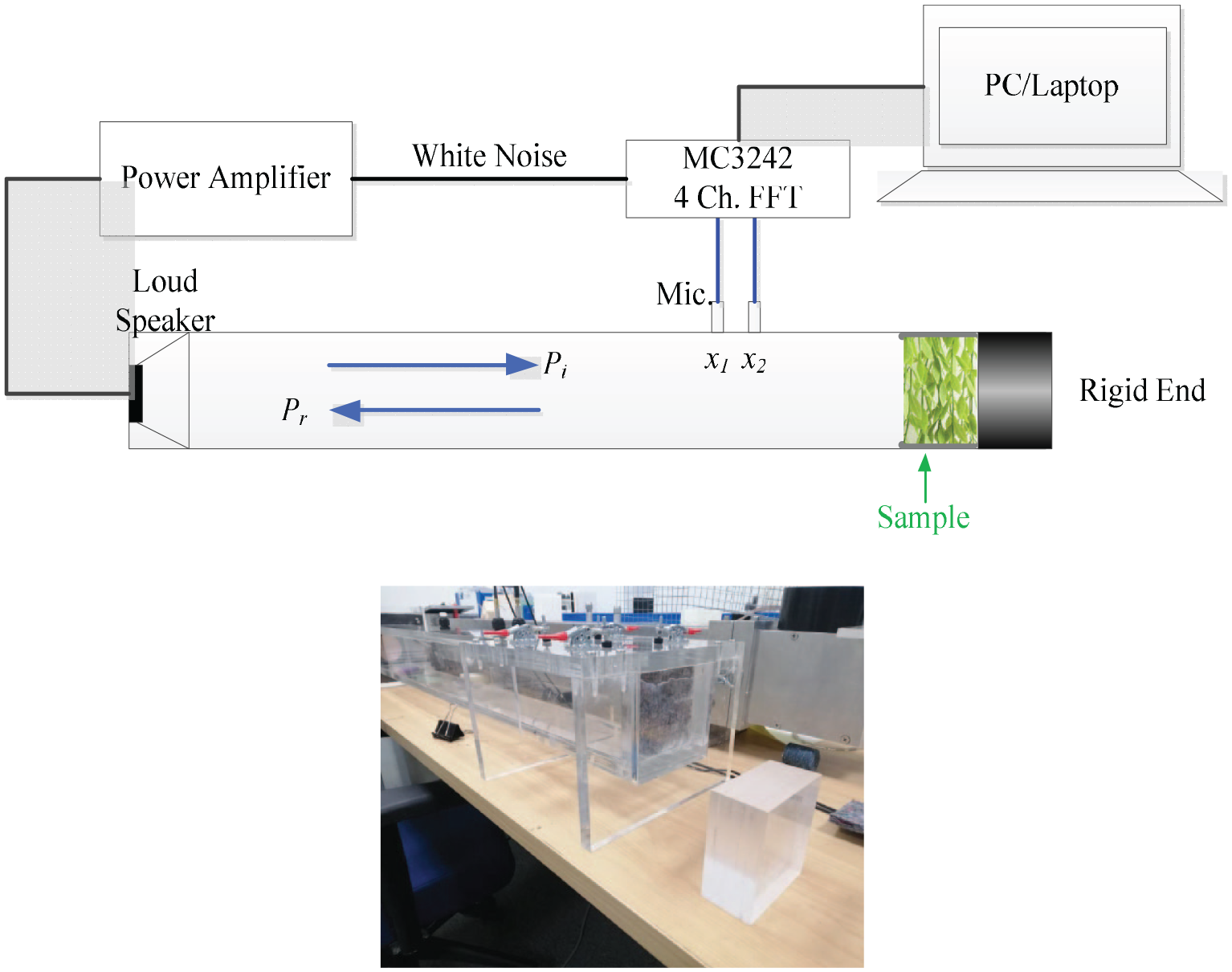
Schematic diagram of the impedance tube test method.
Diffuse sound field
To validate the concept, we developed an experimental rig, as shown in Figure 8. The diameter of each scatterer was 89 mm, and the corresponding lattice distance was 100 mm due to the limitation of opening thickness in the measurement facilities. The scatterers were made of hollow PVC cylinders arranged in a square lattice. It can be seen that the scatterers were used together with the vegetation using an opening size of 50 × 50 cm. Moreover, filler walls were employed beyond this opening,
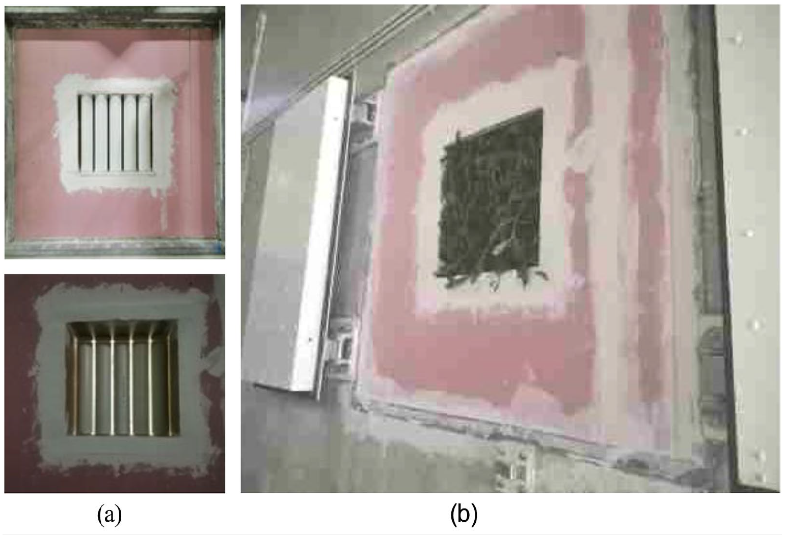
Test sample for validations of combined vegetation and SC: (a) cylindrical hollow PVC, (b) combined cylindrical hollow PVC and vegetation.
The measurements were conducted according to ISO 15186-1 and its arrangement, as shown in Figure 9. The source is on the reverberation room side, while the receiver is on the anechoic chamber side. All transmitted sounds were picked up by an intensity meter. The transmission loss (TL) of the system can be obtained by following the formula,
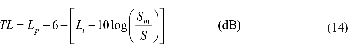
where
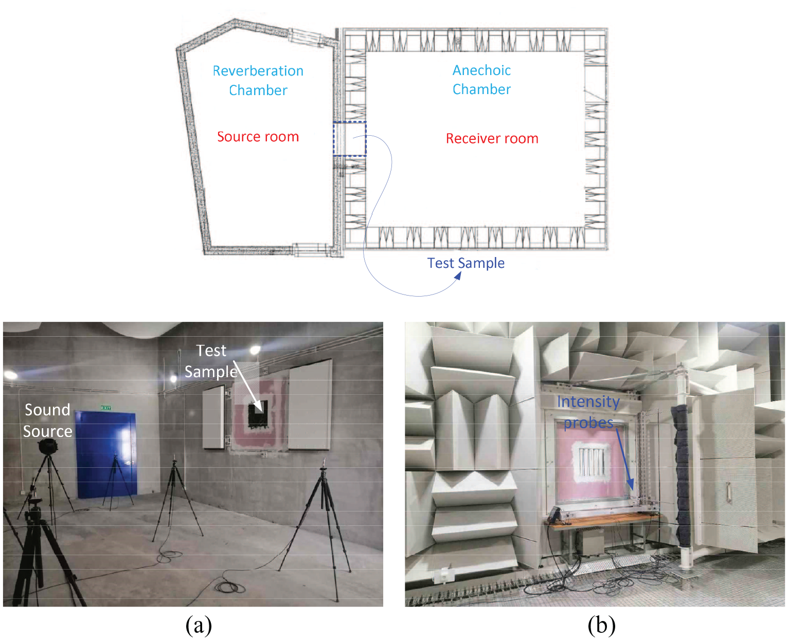
Measurement setup to obtain sound transmission loss: (a) source room, (b) receiver room.
Results and discussions
In this section, the measurement results of the sound absorption characteristics of LKY and Miki’s parameters, which were obtained by fitting them to the measurement results, are presented and discussed. The resulting parameters are then employed in the prediction model, where the behavior of sonic crystal and its combination with vegetation are numerically investigated. Hence, the numerical results and relevant discussions are provided in this section.
Acoustic performance of vegetation
A different amount of foliage can result in different absorption characteristics of LKY. With an absorption measurement impedance tube based as described in section “Vegetation sound absorption,” the more leaves involved in the plant exhibit an increase in the absorption coefficient, particularly at mid and high frequencies, as shown in Figure 10. 0.2 absorption coefficients around 600 Hz are found for 120 leaves of LKY, while 0.35–0.4 absorption coefficients are pronounced at 1600 Hz. Meanwhile, 40 leaves of LKY only show 0.05–0.1 absorption coefficients at the same frequencies. In the case of vegetation, the foliage can be read as a leaf density or the thickness of vegetation. Hence, this can be a key parameter for using vegetation for noise abatement.
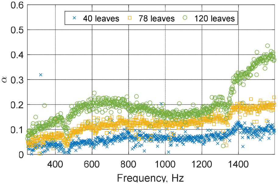
Sound absorption characteristics of LKY due to different foliage characteristics.
Miki parameters for vegetation
To model absorption and transmission characteristics of the sonic crystal green walls, vegetation parameters are required to include Miki’s model
40
in the prediction with the perspective of an equivalent fluid in rigid frame porous media. The applicability of Miki’s model for plants was demonstrated by Horoshenkov et al.,
41
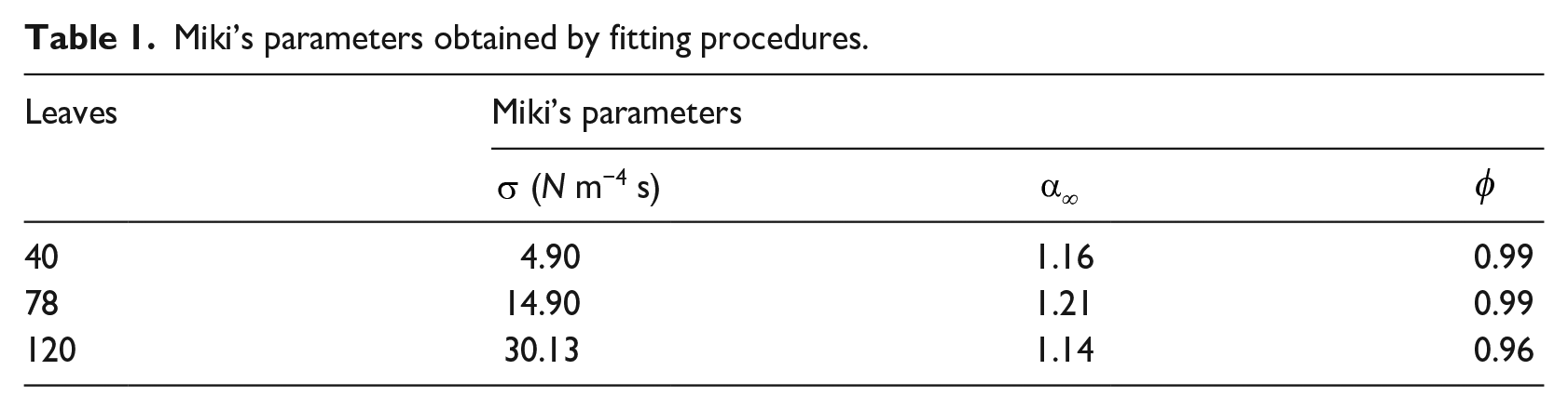
where the porosity and tortuosity data in addition to flow resistivity data can improve the accuracy of the predicted behavior of the acoustic absorption coefficient of a porous medium at medium and high frequencies. In this study, the properties of the vegetation are obtained through a genetic algorithm (GA) based on the measurement results that are implemented using the MATLAB function. The resulting parameters are listed in Table 1, consisting of flow resistivity σ, tortuosity
Miki’s parameters obtained by fitting procedures.
The predicted absorption and measurement results comparisons are in good agreement, as shown in Figure 11. The Miki’s model can provide satisfactory prediction by adding 100% leaf number (see Figure 11(a–b)) and even increased further by around 33 % (see Figure 11(c)). Despite this, a large deviation at a frequency of 1400 Hz and above is seen for the case of 120 leaves. This may be attributed to leaf distribution inside the impedance tube.
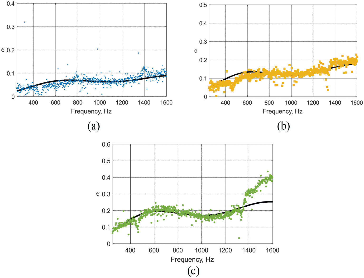
Absorption coefficient comparisons between measurement and modeling results by the Miki model: (a) 40 leaves, (b) 78 leaves, and (c) 120 leaves.
Sonic crystal (SC) behaviour
Dispersion relation
Scatterer diameter
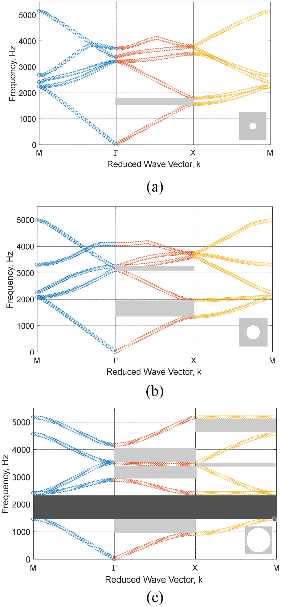
Scatterer unit with associated band gap characteristics: (a)
Attenuation behavior
The corresponding attenuations or transmission loss of each band structure in Figure 12 are presented in Figure 13. Different diameters of scatterers are considered where single SC is repeated in one direction, which is called single layer SC. It is clear that the resulting attenuations between 1 and 2 kHz correspond to a partial band gap in ΓΧ region. The attenuation level increases as the SC diameter increases. These characteristics are evident with more layers increasing, as shown in Figure 13(b–c). However, more attenuations are also present at different frequency regimes as the band gaps are also pronounced at ΧΜ and ΓΜ as found in the case of 89 mm SC. Other than that, increasing the number of SC layers is also useful to attain a greater attenuation, as shown in Figure 13(d) where 48 mm SCs are employed under different layer configurations.
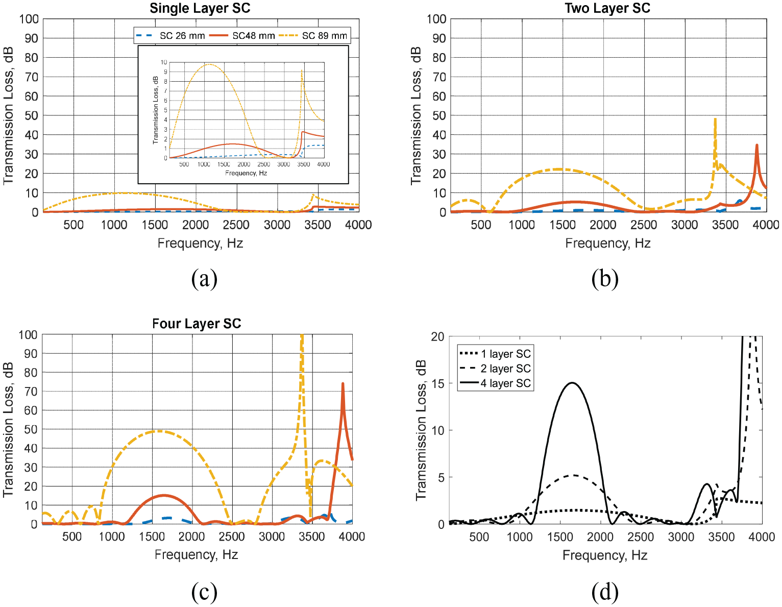
Sound attenuation due to different sizes of scatterers and a number of layers: (a) single layer SC; (b) two layers SC; (c) four layers SC; (d) different layer number for the case of 48 mm SC.
Combination of sonic crystal and vegetation
Two configurations of combined SC and vegetation are considered in the numerical models. Both configurations are developed based on 89 mm diameter scatterers, but the lattice distances are set to 100 and 150 mm respectively, denoted as SC 1 and SC 2 from now on. Meanwhile, the vegetation parameters of 120 leaves are employed in this calculation with a total thickness of 100 and 200 mm.
The TL comparison results of SC 1 can be seen in Figure 14(a). With the main peak around 1400 Hz, the contribution of the vegetation to the overall attenuation is insignificant at this frequency. This condition is persistent at lower frequencies. However, greater additional attenuation is seen at higher frequencies, particularly at frequencies at which the role of SC in the attenuation is lesser. This is consistent with the acoustical performance of vegetation, which is better at high frequency. Moreover, selecting the proper parameters of SC is crucial to ensure the attenuation at high frequencies corresponding with the vegetation instead of the SC hence an improvement is obtained. Such a situation is further depicted in the case of SC 2, as shown in Figure 14(b) where additional attenuation of 9 dB is present while that of SC 1 is only 4 dB at 2800 kHz up to 3.35 kHz. The use of thicker vegetation is also beneficial to increase additional attenuation, as demonstrated by 100 and 200 mm thick vegetation, where 200 mm can provide three times higher attenuation than 100 mm at certain frequencies. The noise attenuation improvement at frequencies above 1 kHz is useful, considering that the human hearing system is sensitive to higher-frequency sound.44,45 Moreover, environmental noise in urban area in some cases contains high frequency components, for example, one of the relevant sources is railway noise. 46 Hence, the enhancement made by vegetation at high frequency is beneficial in this context.
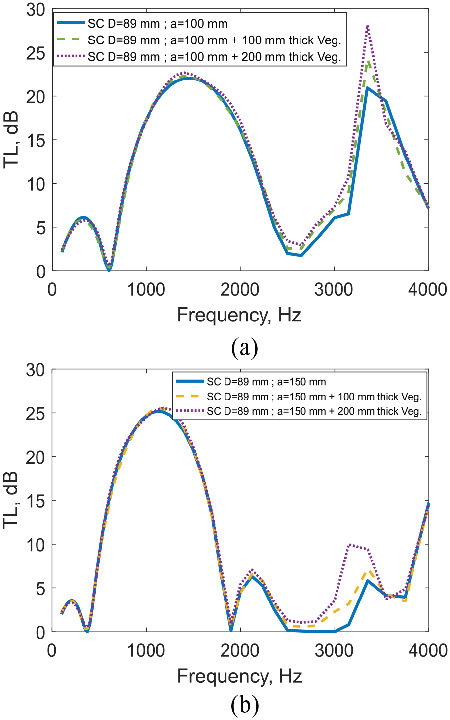
TL comparisons of SC and SC with vegetation: (a) SC with a lattice distance of 100 mm, (b) SC with a lattice distance of 150 mm.
Validation results under diffuse sound field excitation
In this section, the TL of SC only and the combination of scatterers and vegetation are compared with the experimental results as shown in Figure 15. For the case of SC only, the main peak centered around 1.6 kHz is mainly related to the sonic crystal where TL of around 13.5 dB is present. A similar characteristic is depicted by the experimental results as shown in Figure 15(a). Some discrepancies may be attributed to not-totally rigid PVC scatterers, the finite configuration of SC, and the diffraction of filler walls to overall TL. Meanwhile, a slight improvement in TL is found from the combination of SC and vegetation as shown in Figure 15(b) where the TL only increases around 1 dB. This suggests that the sonic crystal dictates the TL behavior for the configuration used in the experimental works. It should be noted that the role of vegetation in this configuration is not seen as vegetation absorption is more useful to increase performance outside of the frequency range of interest. Despite this, such a slight improvement is found in the comparisons. Moreover, the vegetation contribution can be extended based on the key parameters of the porous absorbers, that is, increasing the layer thickness and corresponding flow resistance, as demonstrated in section “Combination of sonic crystal and vegetation.” The results also suggest that the vegetation can be designed to attenuate sound at higher frequencies as is the nature of their performance, while the SCs are designated to attenuate the sound at lower frequencies. Apart from this, this result is promising for obtaining the benefit of vegetation for non-acoustical features and acoustical performance improvement.

TL comparisons between theoretical results and experimental one: (a) SC only, (b) combination of SC and vegetation.
Conclusions
The acoustical characteristics and performance of sonic crystal (SC) green walls have been studied. Vegetation absorptions can be represented by the Miki Model and combined with SC under the equivalent fluid model approach to predict their overall transmission loss. The results are confirmed by the experimental results. It has been demonstrated that the SC is a tunable system to provide a more flexible noise control treatment. To be effective, the SC of the green wall is designated to work at low-mid frequencies attenuation, while the vegetation is employed to enhance attenuation performance at higher frequency noise so that a broadband sound attenuation system can be obtained with a better performance. Otherwise, the attenuation of SC dictates overall attenuation as the TL only increases around 1 dB due to the presence of vegetation. It is also found that increasing the thickness of vegetation in the sense of a layer provides a further additional attenuation, which can be three times higher by doubling the thickness. The combination of both SC and vegetation into a single system can maximize the merit of each component, where vegetation can affect the acoustical and non-acoustical performance. Hence, the use of such a system in an urban environment will be a good alternative to the existing system in order to deal with an interdisciplinary approach in urban design. We believe that this study can provide a framework for noise control design, particularly in urban environments where SC and vegetation are utilized.
Footnotes
Appendix 1. Equivalent Fluid Model for Vegetation Absorption
Vegetations consist of air, stems, trunks, twigs, and leaves that result in a complex medium to be modelled. Theoretically, the viscous losses and thermal dissipation of sound waves as it propagates through vegetation can be modelled using an equivalent fluid model. An empirical model proposed by Miki
40
is evident in providing a good prediction result for plant absorption cases, considering the studies carried out by Horoshenkov et al.
41
and D’Alessandro et al.
42
With three non-acoustical properties namely porosity, tortuosity, and flow resistivity, the model suggests the frequency-dependent characteristic impedance
where
It has been known that the non-acoustic properties are customarily obtained by the inverse method based on measurement data. The plant porosity is the one that can be obtained directly by the ratio of the volume of plant foliage to the total volume occupied by the plant,
The pore tortuosity is related to the structure factor that quantifies the deviation of the velocity wave vector to its actual path through the pore. For the case of vegetation, this parameter can be approximated by the dominant angle of leaf orientation
The flow resistivity of vegetation can be problematic when a measurement approach is used for porous material. The fitting and optimization approach becomes a sensible way to obtain the data.
Declaration of conflicting interests
The author(s) declared no potential conflicts of interest with respect to the research, authorship, and/or publication of this article.
Funding
The author(s) disclosed receipt of the following financial support for the research, authorship, and/or publication of this article: This research is supported by Institut Teknologi Bandung (LPPM ITB), under the PPMI research scheme 2021.