
Abstract
Sonic crystals (SC) have emerged as a promising alternative to conventional concrete sound barriers for mitigating urban noise. The structures attenuate incoming acoustic waves through the formation of band gaps, which result from the periodic arrangement of cylindrical scatterers. The attenuation characteristics are primarily dictated by the diameter of the scatterers and the spacing between them. In this study, we investigate the acoustic performance of SC structures composed of cylindrical scatterers coated with moss plants. Such a configuration is expected not only to enhance noise reduction but also to contribute to urban sustainability by integrating vegetation into the noise control component. Moreover, the SC parameters can be tuned to target specific frequency ranges, making the system adaptable to different urban noise profiles. Our findings indicate that the combination of SC and moss plants leads to improved sound attenuation. It is found that introducing the moss plant on the scatterer surface of the SC can enhance attenuation by as much as 1 dB to 4 dB, depending on the frequency range. Meanwhile, experimental results suggest that attenuation improvements can reach up to 14 dB with similar attenuation behavior. Hence, the proposed structure should be applicable to obtain both acoustic and non-acoustic features in the context of the urban environment toward more sustainable, livable, and resilient cities.
Introduction
Urban noise has been identified as one of the primary sources of pollutants. Such noise is mostly related to road noise and railway noise and is now increasing due to a demand for mobility, which is inseparable from transportation activities. Moreover, the expanding urban areas and new infrastructure are also a determinant factor, where sensitive areas, particularly residential areas, are preferably built around main access to public transport.1–3 On the other hand, harmful noise has been identified to have a negative impact on humans. WHO reported that noise can cause a variety of health issues comprising auditory and non-auditory effects. 4 Meanwhile, noise in cities is a top emerging environmental threat and a growing hazard to public health as reported in UN Environment Programme (UNEP). 5 The situation can hinder the satisfaction of urban design trends in creating more sustainable, livable, and resilient cities.6,7
A multidisciplinary approach in urban design is inevitable to be adopted in order to realize preferable urban environments.8–10 An acoustic parameter should not be the only factor to dictate the final design, but it is also necessary to ensure other requirements are satisfied simultaneously, for example, esthetic value, saving energy, cost reduction, CO2 absorption, etc. It has been known that sound barriers are a practical noise control component used to mitigate road noise. The use of solid partitions or walls are commonly found and erected along the road, separating the noise sources and receivers in sensitive areas in the context of noise propagation. This works well where sound attenuation of 8–15 dB is present, although it sacrifices the urban visual as the noise barriers are often visually dominant construction. Moreover, there is an indication that esthetic preference affects the noise barrier performance perception. 11 Meanwhile, the use of vegetation or green space at the roadside can be useful for public health for example, dealing with the growth of cardiovascular diseases (CVDs). 12 In a specific case, the concrete wall system can prevent air circulation within the protected area or block the walking path for interconnection access. Sonic crystal (SC) is proposed as an alternative solution to alleviate such a problem. 13 The system works on the band gap mechanism that is created by the scattering of cylinder components arranged periodically in certain directions and a certain distance, so called lattice distance. 14 Such a configuration allows the SC structure to have a gap between the scatterers, which is beneficial for air circulation and natural light. The band gap can create a pass-and-stop band to an incoming wave so that some sound attenuation can be obtained. From this point of view, SC is more acceptable for use in satisfying the urban trend. Despite this, greenery visuals, which are likely to be envisioned from the urban environment, have not been explored much. Some efforts on this can be attributed to the sonic crystal green walls, 15 the use of wooden materials as scatterers16,17 or arranged tree-like SC. 18
The green space or vegetation has indicated some benefits not only in noise reduction but also in other aspects of environmental concerns in fulfilling public health, livable, sustainable, and resilient. The use of vegetation in urban environments has brought positive effects to thermal comfort, air quality, noise reduction, hydrology, and biodiversity.19,20 This is adopted either as vertical greenery system or added to other system for enhancing the visual appeal. For noise control, the vegetations indicate their capability to attenuate the noise, particularly at a high frequency regime. Hence, it is plausible to use them in a systematic way while combining with conventional noise control components to benefit tunability as well as extend the attenuation bandwidth. Hence, the resulting system can have a wider application, particularly in dealing with road noise, which is a dominant component of urban noise. Apart from this, the selection of vegetation should be done with great care. This is related to the practical constraints of the ease of maintenance, attractiveness, and variation. For such a situation, moss plants (Bryophyta) are a good candidate for the system.
In this study, the use of SC is considered while the moss is explored to know its acoustical characteristics. Combining the moss with the SC is expected to allow the attenuation capability of the system to be tunable, while some enhancement is present due to the absorption of the moss. Moreover, having both components in a single system can be useful for enhancing its functionality in terms of both acoustic and non-acoustic features, addressing the multidisciplinary approach expected from the urban design trend. For this, absorption characterization is carried out. The resulting behavior of the combination is investigated numerically using the Finite element method. Finally, experimental validations are provided.
Methodology
Sonic crystal (SC)
The arrangement of scatterers and the associated main direction of symmetry in the reciprocal space of the path ΓΧ-ΧΜ-ΓΜ can be seen in Figure 1. ΓΧ and ΓΜ refers to the [1 0] direction and the [1 1] direction respectively, while ΧΜ refers to the wavevector varying from [1 0] to [1 1] on the side of the Brillouin zone. The resulting attenuation of a sonic crystal corresponds to band gap characteristics represented by the center frequency and bandwidth. The center frequency of periodic structure can be set according to Bragg’s law where the frequency is proportional to the ratio of sound speed

A unit cell of an infinite sonic crystal system with periodic boundary conditions.
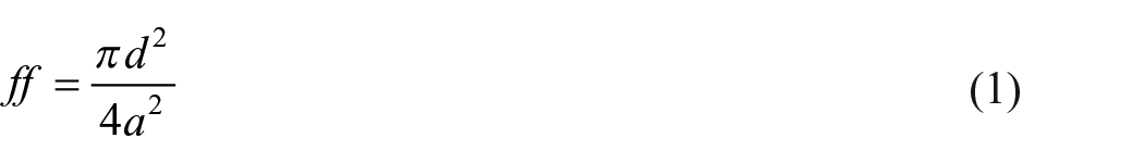
where
Evaluating the frequency response of a sonic crystal simply requires an analysis of the periodic unit cell. For this, the Floquet-Bloch boundary conditions are considered on the edges of the unit cell to represent the periodicity of the system as follows,

where
Moss plants
Moss plants (Bryophyta) are one of the biodiversity in the world, with almost 1800 species. This plant belongs to the evolutionary oldest land-plant group that can grow in a wet environment attached to substrates such as rocks, trees, wood, and soil. These plant structures do not have roots, seeds, or flowers, as shown in Figure 2. Moss does not need chemical substances like fertilizers or pesticides and minimal watering. Hence, the moss is a low-maintenance plant compared to other plants. Moss is usually considered a part of the soil substrate for the benefit of vascular plants. Hence, the porous structures are already present in such a plant, which is promising for sound absorbers. Moss can also enhance visual appeal, offering a natural and attractive esthetic, making it suitable for use in urban buildings.
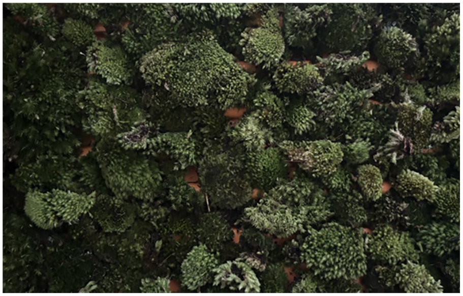
Moss plant used for the proposed sound barrier.
Basic structure
The combination of SC structures and moss plants proposed in this study is illustrated in Figure 3. The scatterer surface of the SC is fully coated by the moss with an overall thickness of 20 mm. Hence, the moss is allowed to live over the scatterer surface as naturally as possible. With such a configuration, the surface of scatterers is not totally reflected but partly becomes absorptive as a consequence of the moss on their surface. It is expected that overall attenuation is increased due to a combination of the Bragg’s resonance of the periodic structure and the absorption of the moss plant on the scatterer surfaces. Moreover, the system is tunable to meet a specific targeted sound attenuation as the basic characteristics of SC attenuation are still held and determined by the scatterer’s diameters and associated lattice distance. Apart from that, the proposed structures can deal with acoustic and non-acoustic features to deal with noise reduction, as well as health and a sustainable environment that benefits the vegetation roles.
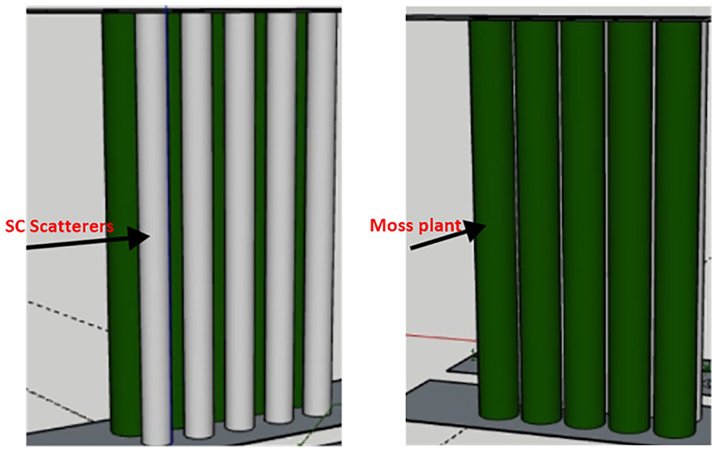
Basic structure of scatterers coated by moss in the SC structures.
Modeling of sonic crystal and moss
Finite element method (FEM) model
A Finite Element Method (FEM) model is developed to calculate band gaps and associated transmission loss (TL) developed using FEM commercial package software (COMSOL Multiphysics 5.6). The model consists of four main domains, as shown in Figure 4. The first and four domains are related to the Perfectly Match Layer (PML) region, which is employed to allow anechoic terminations of the waveguides. The second domain is defined for the background pressure incident
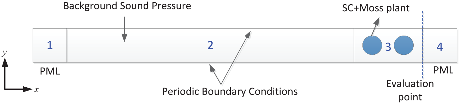
Numerical model and associated domain for SC coated with moss.
Figure 5 presents the moss situated on the cylinder scatterer surfaces and its implementation in the numerical model. The blue circle indicates the SC, while the green one is associated with the moss on the cylinder surface, which has a particular thickness. The moss is modeled as a porous material and considered a homogenous medium from a macroscopic point of view, where it can be treated as an equivalent fluid in rigid frame porous media. For this, Miki’s model
23
is adopted following the applicability of Miki’s model for plants as demonstrated by Horoshenkov et al.,
24
where the porosity and tortuosity parameters in addition to flow resistivity data can improve the accuracy of the predicted absorption coefficient of a porous medium at mid and high frequencies. In this study, the properties of the vegetation are obtained using a parameter inversion approach based on a genetic algorithm (GA), which is implemented using the MATLAB function
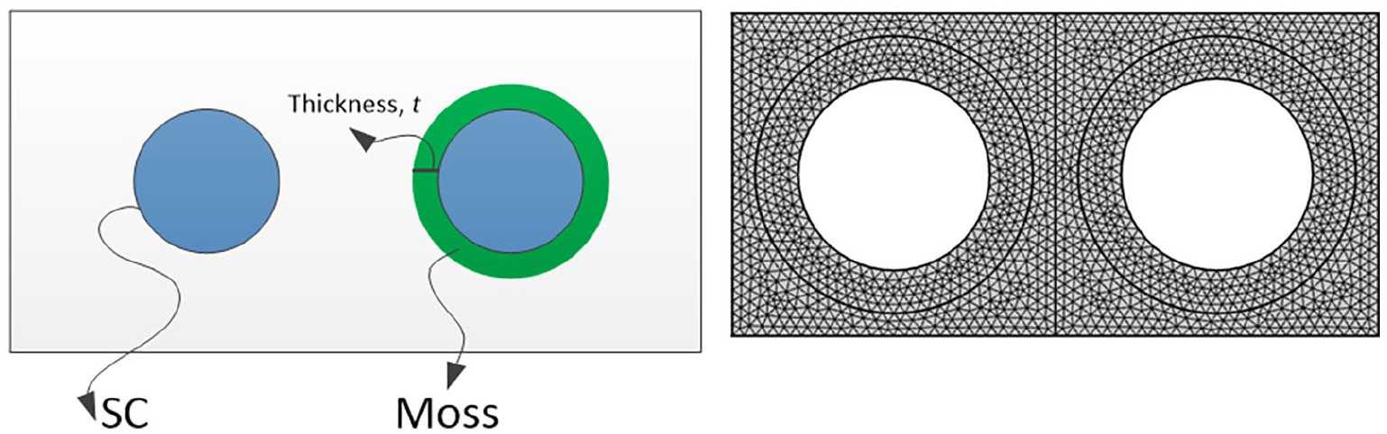
Illustration of moss attachment on the scatterers and its implementation in the numerical model.
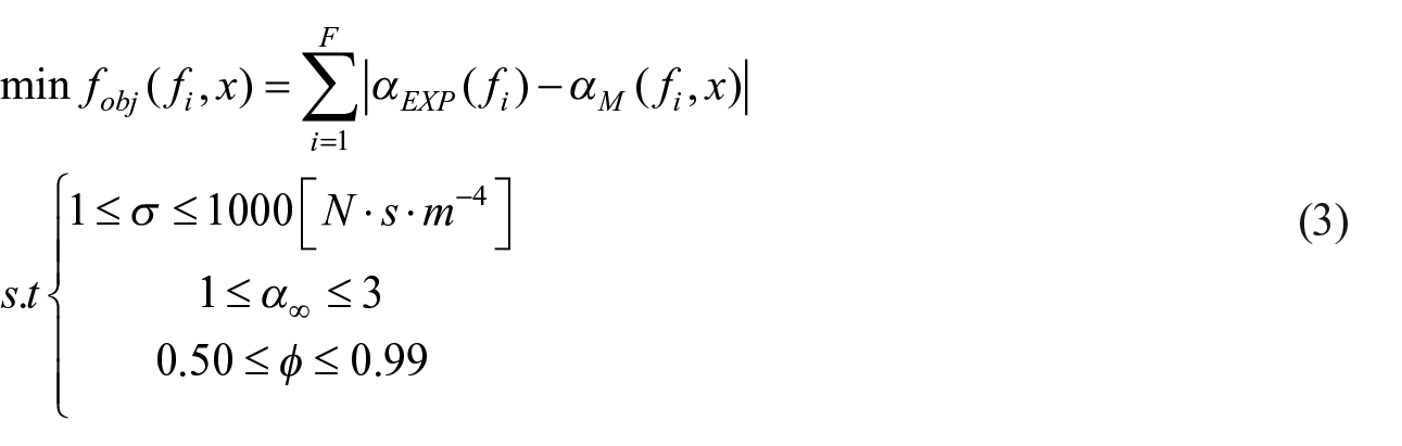
where
The incident sound power Winc is determined as follows,
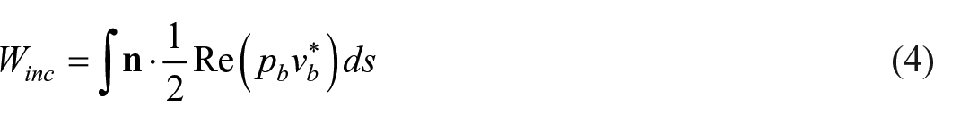
with
The total transmitted sound power Wtrans is evaluated at the back surface of the system, from which the transmission coefficient
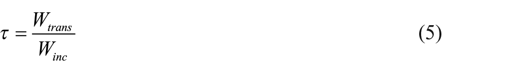
From equation (5), the transmission loss of the system is then defined as
3D FEM model of diffuse sound transmission loss
Figure 6(a) presents the schematic model of diffuse sound transmission loss. It was developed by assuming an ideal diffuse sound field on the source side, where a sum of
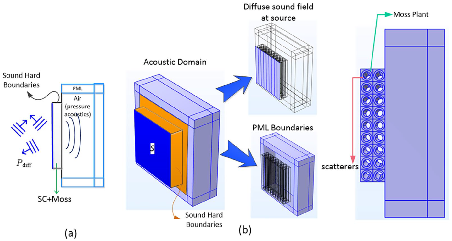
Schematic model of diffuse sound transmission: (a) model setup of diffuse sound TL and (b) 3D FEM model to obtain diffuse sound transmission loss.

where
Therefore, the total pressure on the source side can be obtained as a superposition of all individual plane wave as
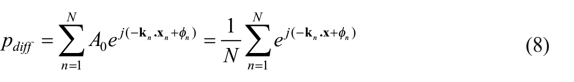
Since the amplitude
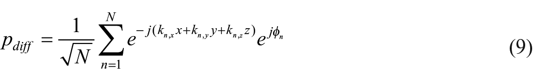
with
The implementation of this model setup can be seen from Figure 6(b). The diffuse pressure
The incident intensity over the test surface area on the source side can be calculated using the following expression,
with
where
where
Experimental validations
Sound absorption
Two species of moss are considered and compared before being employed as a coating for the SC. The specific names of species are unknown, but these mosses are mostly available in the market with different structures as shown in Figure 7 and denoted as Moss-1 and Moss-2. Moss-2 possesses an even substrate and is wetter than that of Moss 1. The moss was placed on the sample holder, which was 2 cm thick. The measurements were conducted based on ISO 10534-2 with the setup illustrated in Figure 8. This measurement was carried out in two steps, namely the first step is a measurement with a frequency range of 100–500 Hz. During the measurements, the microphones were swapped for phase correction. From this procedure, two transfer functions
The setup of moss in the impedance tube for obtaining sound absorption coefficients: (a) Moss 1 and (b) Moss 2.
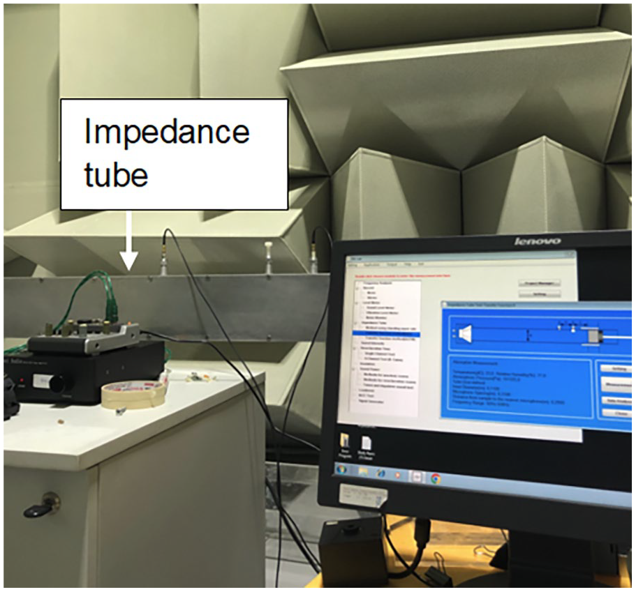
Measurement setup of sound absorption using an impedance tube according to ISO 10534-2.
Sound transmission loss
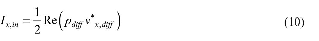
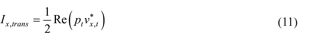
To validate the concept, two distinct sample configurations (SCs) were developed to evaluate the performance of the proposed system, with particular focus on the effect of moss on overall sound transmission loss as shown in Figure 9. For this, the first SC configuration is made by periodically constructing 89 mm diameter hollow PVC cylinders with a lattice distance of 150 mm in the x and y directions. In finite dimensions, two layers of periodic configurations in
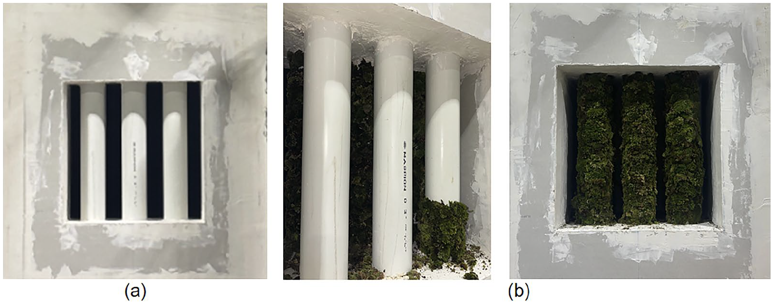
Test sample of scatterers coated with moss plants (a) first SC configuration and (b)second SC configuration.
The experimental validations are intended to assess and verify the behavior of the proposed system as indicated by the numerical calculations. The proposed structure behavior is discussed in the absence of a ground surface. Hence, the measurements were conducted according to ISO 15186-1 where the standard arrangement is shown in Figure 10 rather than for standard measurement for the sound barrier as adopted in Refs.26,27 For this measurement, the source is on the reverberation room side, while the receiver is on the anechoic chamber side. The samples were then put on the 0.5 m square opening situated between the source and receiver rooms.
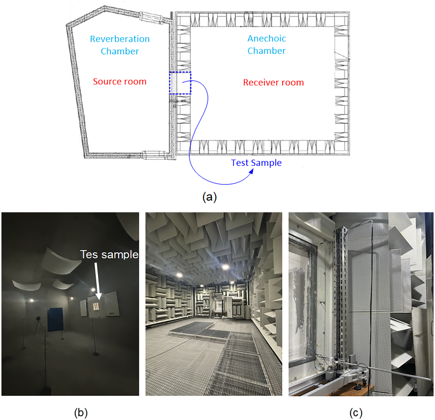
Measurement setup to obtain sound transmission loss: (a) test sample placement in the reverberation chamber-anehoic chamber, (b) reverberation chamber for source room, and (c) anechoic chamber for receiver room.
Results and discussion
Absorption behavior of moss
Figure 11(a) presents sound absorption comparison between Moss-1 and Moss-2. The two types of moss exhibit similar absorption coefficients at frequencies below 700 Hz. However, Moss 2 indicates better performance above this frequency, where the difference can be up to 2 points. This suggests that moss with a more humid and greater soil substrate is preferable for absorbers. In this study, moss-2 is further used to coat the scatterers. Meanwhile, the flow resistivity σ, tortuosity
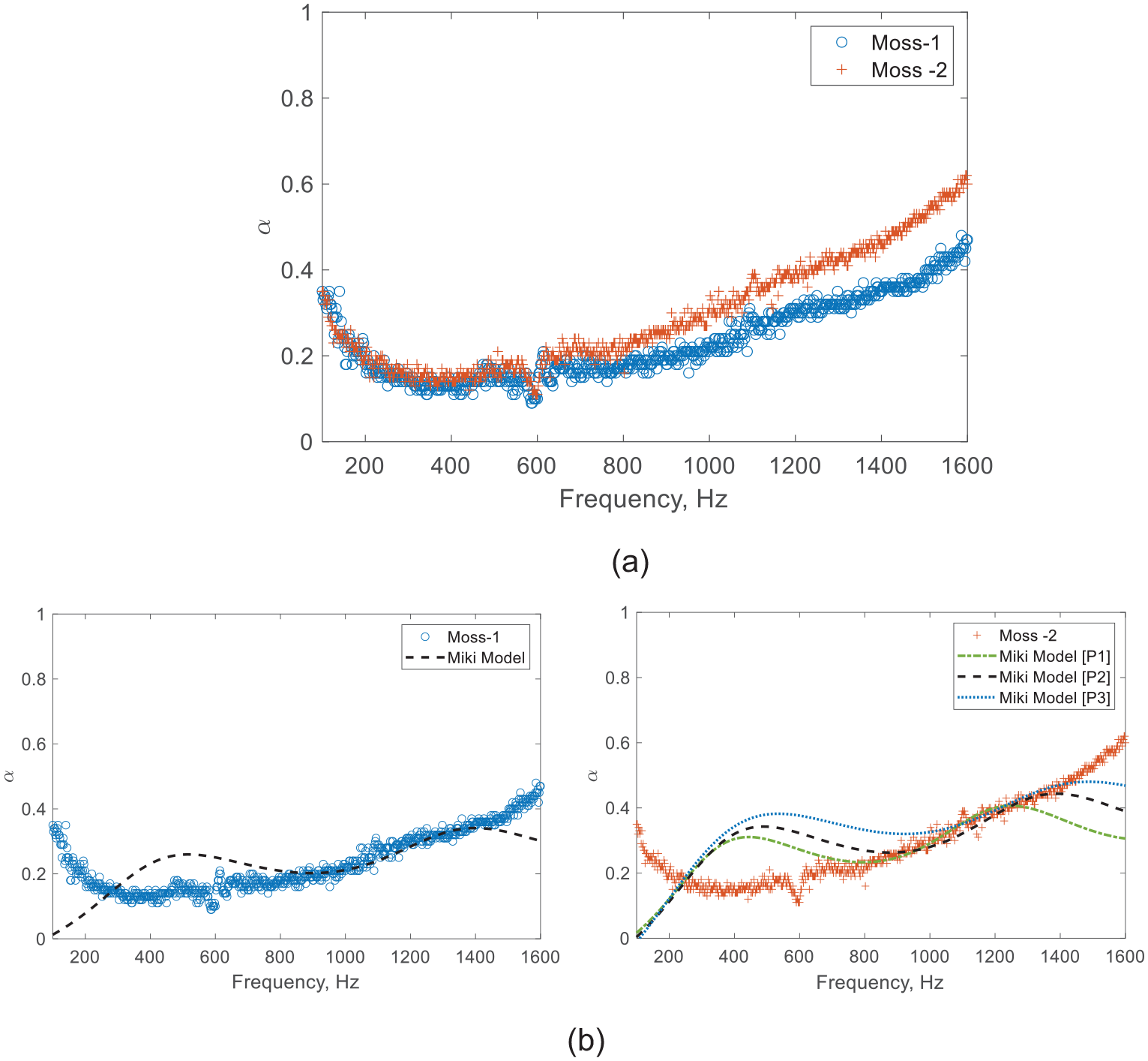
The sound absorption coefficients of Moss-1 and Moss-2: (a) experimental data of Moss-1 and Moss-2 and (b) absorption coefficient comparisons between measurement and modeling results by the Miki model.
Miki model parameters for Moss.

Compared to the experimental results, the predictions exhibit that the resulting spectrum does not coincide with the experimental ones at all frequencies, as shown in Figure 11(b). The difficulty arises due to the effect of moisture content and non-uniform porosity resulting from the distribution of the non-vascular leaves of the moss. This implies that the variation in the data range and the variables optimized in the fitting procedure can result in different parameter values for different frequency coverages. For comparison purposes, we list three different sets of parameters for the case of the Moss-2, denoted as P1, P2, and P3. Hence, the parameters for the numerical model are drawn from the best fitting over the widest frequency coverage, following the porous model capability offered by the Miki model. For this reason, parameter P2 is employed in the numerical model, unless stated otherwise, which is subsequently used for validation.
TL and band gap characteristics
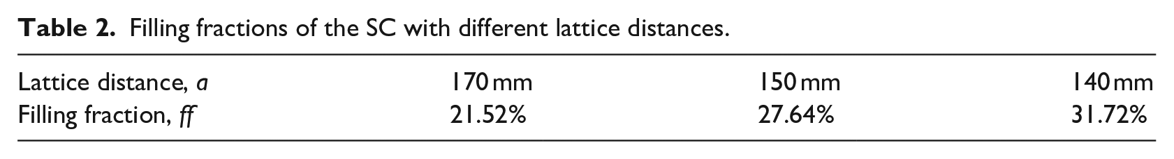
The transmission loss (TL) behavior of the SC is discussed as a result of lattice distance variation. The lattice distances of 170, 150, and 14 mm are considered for analysis. It has been described in the methodology section that the lattice distance determines the filling fraction, considering the constant scatterer diameter as listed in Table 2. It can be seen that each lattice distance configuration dictates the transmission loss, as shown in Figure 12. The highest filling fraction, which is associated with a lattice distance of 140 mm, can produce higher attenuation and a wider attenuation bandwidth. Meanwhile, reducing the filling fraction by 4% can result in a 2.7 dB decrease in attenuation. Moreover, it is observed that a 7 dB difference in attenuation occurs for a 10% difference in filling fraction, where the associated attenuation bandwidth can vary by up to 190 Hz.
Filling fractions of the SC with different lattice distances.
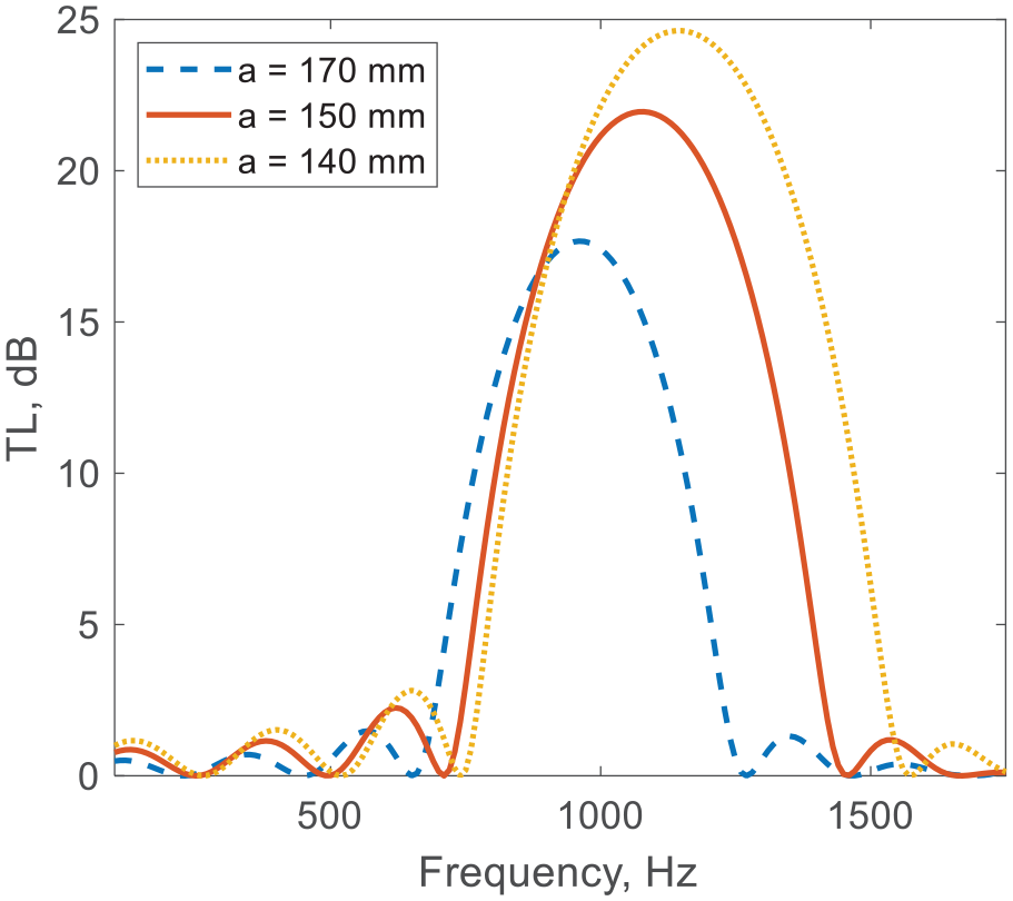
Transmission loss comparison due to different filling fraction.
To confirm the transmission loss behavior in Figure 12, the band gap characteristics are developed as shown in Figure 13. It can be seen that the band gaps are present in the ΓΧ region for all lattice distances. The shorter the lattice distances, the wider band gap exists for a similar frequency region as shown by the light gray rectangle, as indicated by the 140 mm lattice distances case. This phenomenon occurs due to the wave interference and Bragg scattering mechanisms becoming more substantial as a consequence of shorter wavelengths. The wider bandwidth explains the presence of the peaks in the transmission loss curve. Meanwhile, the longer lattice distance causes a smaller band gap, and also the band gap becomes narrower as seen in the case of 170 mm lattice distance. Hence, increasing the filling fraction is beneficial for both widening the attenuation bandwidth and creating more resonant peaks in the transmission loss curve. Under a proper filling fraction, destructive interference can be guaranteed, which in turn leads to more sound attenuation produced by SC. This also suggests that the SC in the proposed structure can be a tuning parameter for overall performance.
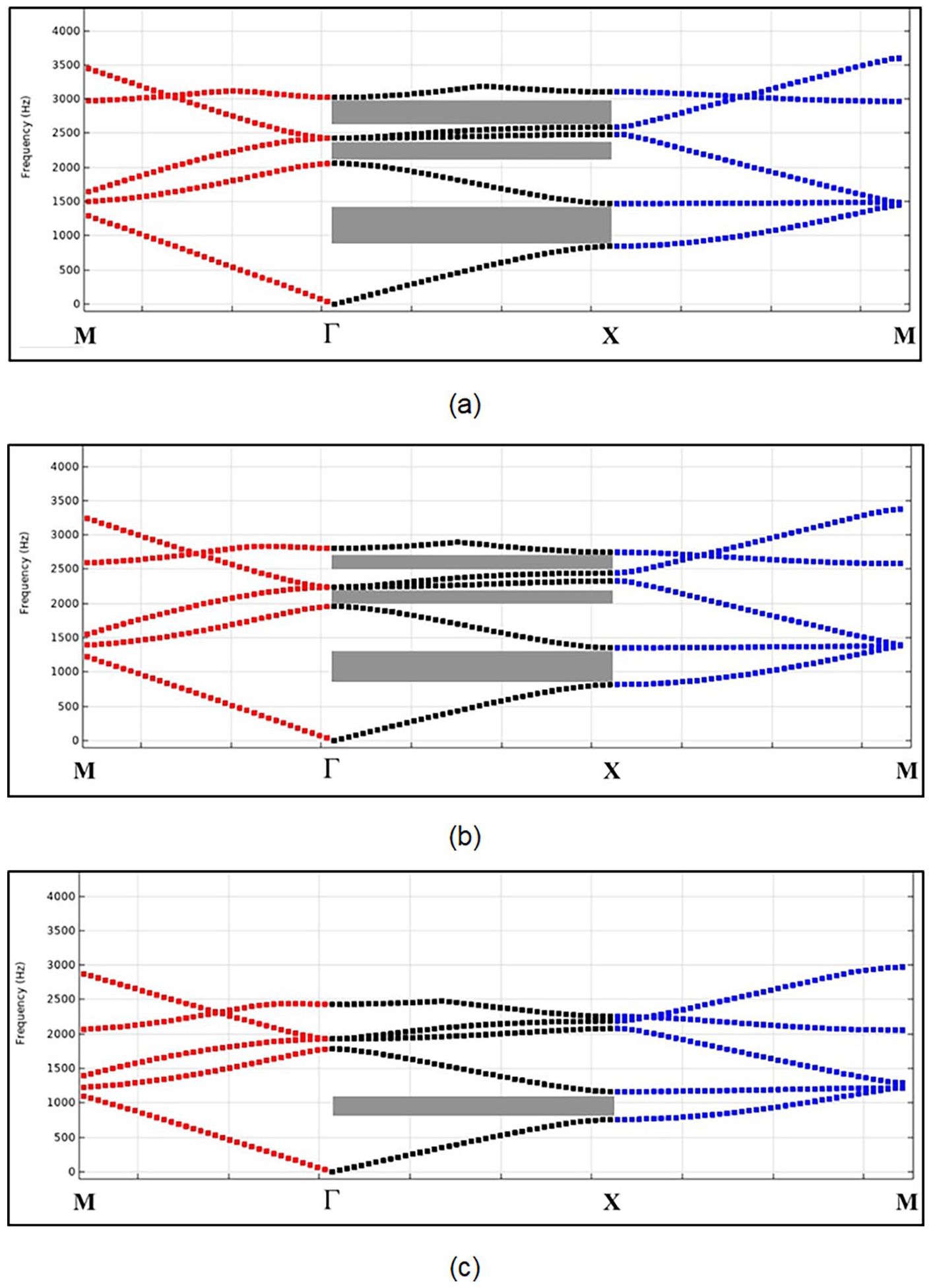
Scatterer unit with associated band gap characteristics due to different lattice distance: (a) a = 140 mm, (b) a = 150 mm, and (c) a = 170 mm.
Influence of moss on the attenuation behavior of SC
In this section, 20 mm thick moss is considered to adhere to 89 mm diameter scatterer surfaces. Compared to the SC configuration only, the presence of most plants on the scatterers does not change the basic behavior of SC. This can be observed from Figure 14(a) and (b) where the transmission loss of the SC with and without moss is compared. For different lattice distances, the behavior of both configurations is the same, that is, increasing the filling fraction by reducing the lattice distance results in a wider attenuation bandwidth. However, the moss plants cause the Bragg resonance frequency to shift to a lower frequency, that is, 810 Hz is observed from SC with moss instead of 960 Hz. Moreover, the attenuation is also higher by 7 up to 9 dB. Hence, such an improvement can be attributed to the moss plant. The role of sound absorbers in enhancing the attenuation is also indicated by other studies, as reported in Refs.28,29
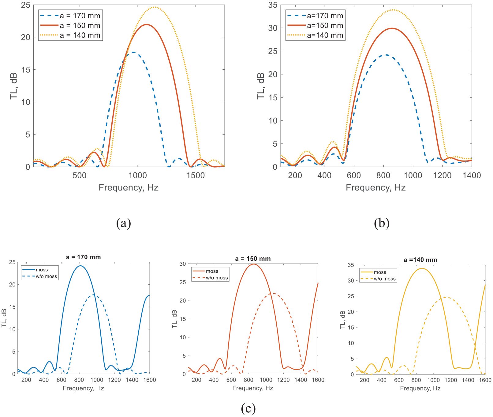
Transmission loss comparisons between SC and SC with moss for the same lattice distance: (a) SC without moss, (b) SC coated with moss, and (c) TL comparison for each lattice distance.
The resulting improvement observed from the case of the SC with moss is not related to a higher filling fraction issue, although the moss thickness on the surface has extended the overall diameter of scatterers from the original rigid scatterers. This can be further investigated by using an equivalent diameter of scatterers as a summation of the original diameter and the moss thickness, so-called equivalent SC. The TL comparison results can be seen from Figure 15. It is clear that the TL behavior of the SC+Moss is different from that of the equivalent SC. Meanwhile, the TL of the SC at bragg’s resonance frequency is lower than that of the equivalent SC due to a higher filling fraction. Hence, the presence of the moss plant on the surface of the scatterers has altered the surface impedance of the scatterers, thereby shifting the peak of transmission loss to a different frequency. Such a mechanism has been discussed in Refs.30,31 or in a specific case related to lossy sonic crystals. 32
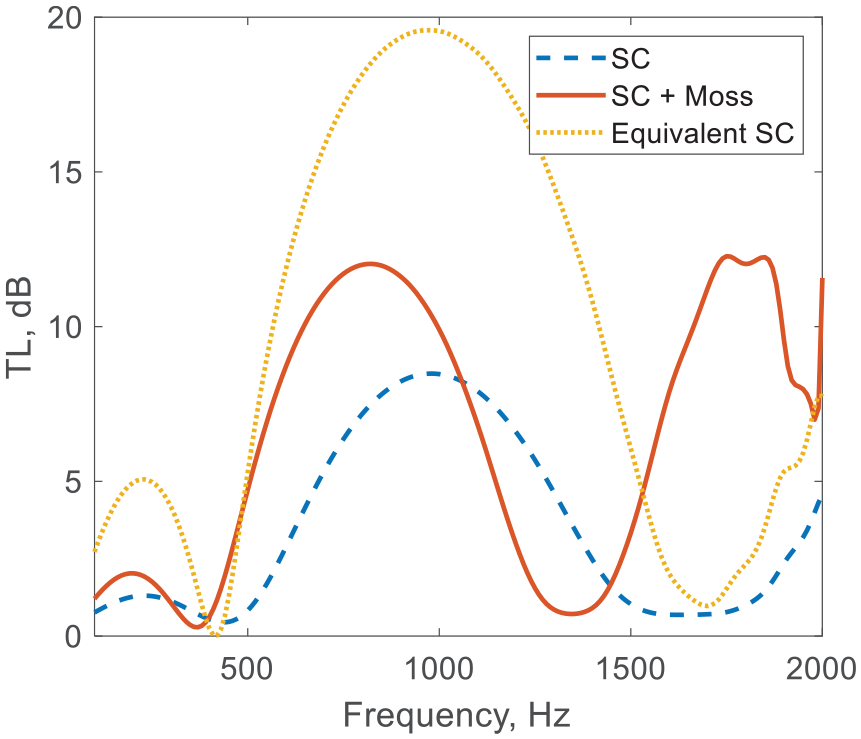
Transmission loss comparison between SC, SC+Moss and equivalent SC that represent SC using scatterers with diameter equivalen to SC+ Moss.
It is instructive to investigate the moss contribution to overall TL further by varying the moss thickness on the scatterer surface. The moss thicknesses of 10, 20, and 30 mm are considered, and the corresponding transmission loss is presented in Figure 16. It is clear that thicker moss can lead to higher transmission loss, that is, a 30 mm thick moss. With the same scatterer diameter and lattice distance, this occurs due to the absorption capability of the moss. Additionally, the peak of the TL shifts to a lower frequency as the thickness increases. Such behavior usually is present in the case of porous material absorption.33–35
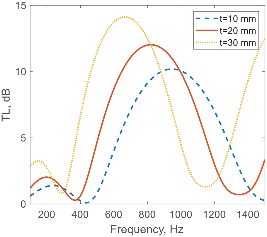
Effect of the moss thickness on transmission loss.
Validation results
Figure 17 depicts transmission loss comparison between the system consisting of SC only and the system with SC coated with the moss plants. The result indicates that an improvement in TL is present when moss is added to the system that is, 3 dB higher is found at 1 kHz and even greater, 5 dB up to 14 dB is pronounced at 2 kHz and above. Meanwhile, numerical results suggest the improvement of 1 dB up to 4 dB for the same frequency range. Hence, the presence of the moss plant as dissipative materials is useful in improving the SC performance, particularly at mid-high frequency.
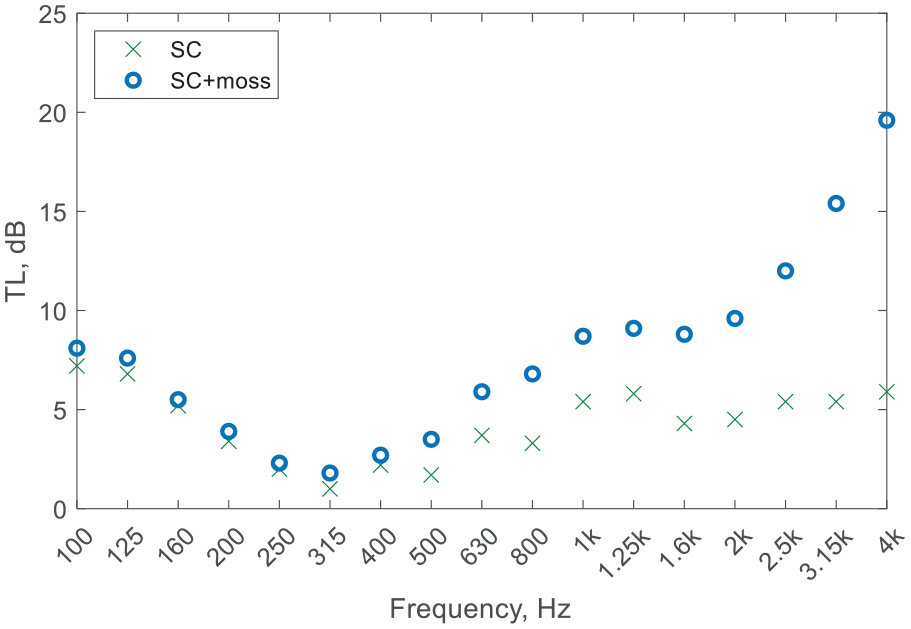
Experimental results of sound transmission loss between SC configuration and SC coated with moss plants configuration.
Figure 18 presents numerical and experimental results for all configurations where the SC only configuration and the SC is coated with the moss plant. For the case of the SC only, the diffuse TLs of both numerical and experimental results coincide over almost the entire frequency range, as indicated by Figure 18(a). The average discrepancy of 1.3 dB exists for this configuration, while the Root Mean Square Error (RMSE) of 1.6 is present for this comparison. Hence, the behavior of the model is sufficiently verified by the experimental results. Similarly, the behavior of SC coated with moss can be verified by the experimental result, where the discrepancy between the results shows the average deviation of 2.8 dB or 4.4 in terms of RMSE (see Figure 18(b)). The discrepancies increase as frequency increases, particularly for frequencies above 1 kHz. For this frequency regime, the TL difference between the results can be up to around 11 dBA. This may be related to the main parameter of porous materials. Hence, it is instructive to investigate further the source of the discrepancy by employing a higher flow resistivity
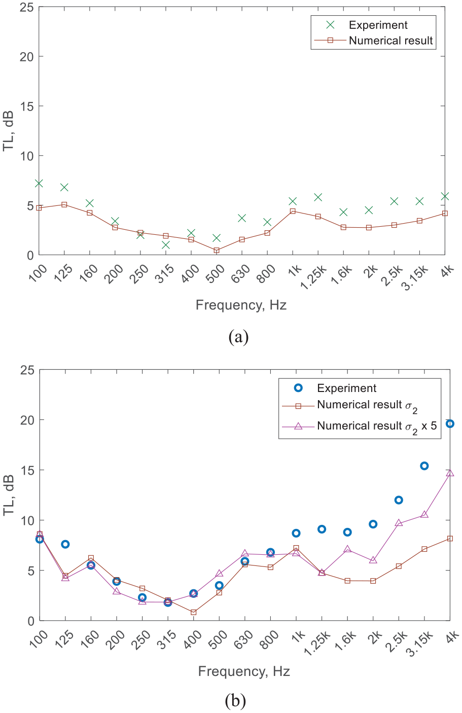
Transmission loss comparisons between numerical and experimental results: (a) SC only case and (b) SC coated with moss case.
Conclusions
Sonic crystal (SC) coated by moss plant as sound barrier is proposed and developed. It has been known that moss plants are classified as low-maintenance plants. This plant can also enhance visual appeal, offering a natural and attractive esthetic, making it suitable for use in urban buildings. In this study, the moss plant is adhered to the surface of scatterers in the SC system. The associated behavior is then calculated and analyzed numerically using FEM. The results suggest that improvement in attenuation performance is present compared to that of the SC only configuration, particularly at higher frequencies. The thicker the moss plant used in the SC, the higher the improvement in TL. Nevertheless, the SC configuration still determines the basic behavior of the proposed system. This implies that the scatterer diameters and lattice distance of the SC need to be determined first to meet a specific target of attenuation before adding the moss plant into the system. From the experimental results, attenuation improvement of up to 3 to 14 dB can be achieved, depending on the frequency range, while the numerical results suggest an improvement of 1 to 4 dB. Despite this, both the numerical model and experimental results exhibit similar behavior and benefits of moss usage in the SC configuration, particularly at higher frequencies. Such performance is promising to be adopted for urban noise mitigation, where acoustic and non-acoustic features are present simultaneously. Hence, the requirement of urban design in creating more sustainable, livable, and resilient cities can be better addressed. Additionally, further study is required to characterize moss for acoustic parameters in order to have a more accurate numerical model.
Footnotes
Declaration of conflicting interests
The author(s) declared no potential conflicts of interest with respect to the research, authorship, and/or publication of this article.
Funding
The author(s) disclosed receipt of the following financial support for the research, authorship, and/or publication of this article: This research is supported by Institut Teknologi Bandung (LPPM ITB), under the PPMI research scheme.