



Abstract
This article introduces a new method, active flow field control through steady suction, to reduce wind loads on buildings. To test its effect, suction equipment was developed and installed on a Commonwealth Advisory Aeronautical Research Council super high-rise model. A series of experiments were then conducted in a wind tunnel. The effectiveness of this method for reducing wind loads is discussed through comparison of the suction bottom moment ratio under different wind incidence angles and different positions of steady suction. The results of the experiment demonstrate that steady suction reduces wind loads effectively.
Introduction
The ever-increasing height of high-rise buildings introduces new levels of structure flexibility and enhanced sensitivity to wind loads. Therefore, wind-induced effect is becoming the main control factors for designing super-tall buildings. A strong wind will cause super-tall buildings to vibrate in the along-wind, across-wind, and torsional directions. This is especially pronounced when the wind fluctuation period is close to the structures’ natural period. The formation mechanisms of wind-induced effects are very complicated. Gerrard (1966) suggested that for a two-dimensional (2D) square body, the flow separation point is generally at the windward sharp edge position. When turbulent wind flows around a bluff body, a turbulent shear layer forms. Within the layer, concentrated vortices appear because of the strong adverse pressure gradient and viscosity. The vorticity of the concentrated vortices is continually supplied by the shear layer; later, the concentrated vortices will be broken. Then, the broken vortices are influenced by the incoming flow so that they shed from the leading edge. Because the phenomenon above appears intermittently, the pressure on the two-side surfaces of the bluff body distributes unevenly in the time and space domain, thereby forming an unsteady lift force (Nakamura et al., 1991). For a wall-mounted, finite-length rectangular cylinder, the shedding vortices have a three-dimensional (3D) structure because of the effect of the free end and the ground wall. Therefore, the formation of the vortex is different from the 2D bluff body (Okamoto et al., 2009; Wang et al., 2004). The flow field around it is more complicated than that around a 2D body. Many researchers have tried to find a model to accurately describe the flow structure (Etzold and Fiedler, 1976; Wang et al., 2005; Wang and Zhou, 2009).
At present, control of wind-induced vibrations in super-tall buildings is mainly achieved through mechanical control measures and aerodynamic control measures. Mechanical control measures may include passive control, active control, or hybrid control (Hudson and Reynolds, 2012; Namcheol et al., 2012; Rotea et al., 2010). Aerodynamic control reduces wind loads by modifying the flow field around buildings with either passive or active methods. Passive methods to reduce wind-induced effects typically involve changing the shape of buildings (Gu, 2010; Kawai, 1998; Ning et al., 2005; Yukio and Hideyuki, 2010). Active methods to reduce wind-induced effects rely on external energy to improve the flow field around a structure. Research on active aerodynamic measures for controlling wind-induced effects on civil engineering structures is a relatively recent field, especially experimental research of suction control methods and their effectiveness on super high-rise buildings. Suction control works through suction flow, which can improve the flow field. Suction is an active method for controlling wind flow around objects, a subject studied extensively in the aeronautical engineering discipline. In aircraft application, suction is a proven method for reducing drag and increasing lift (Kubo et al., 1999; Munshi and Modi, 1997). Recently, the effects of suction on other bodies have been widely studied in other fields. Delaunay and Kaiktsis (2001) studied the effects of base suction and blowing on the stability of the flow around a circular cylinder at low Reynolds numbers (Re ≤ 90). Based on numerical simulations, Li et al. (2003) observed that the vortex shedding of the cylinder can be suppressed by flow suction/blowing with Reynolds numbers up to 110. Arcas and Redekopp (2004) explored the effect of blowing/suction on the characteristics of vortex shedding from a plane forebody with a rectangular base. However, the research on suction-based flow control is barely studied in civil engineering. Xin and Ou (2008) introduced suction control into the field of bridge wind resistance. Their numerical research (Xin and Ou 2008; Xin et al., 2011) results showed that the boundary layer separation was suppressed and that the flutter stability was thereby improved by steady suction–based flow control.
Steady suction means that the velocity of the suction flow remains constant. For a body with a continuous-curvature shape, suction control is applied to remove decelerated fluid particles from the boundary layer before they separate (Schlichting et al., 2000). Therefore, the separation is suppressed, and thus, the drag force is reduced. In civil engineering, the control of lift force is always significant for flexible structures. The control mechanism of suction for a bluff body with a sharp edge is very different from that for a streamlined body. As the vortices shed from the bluff body, a reversed velocity circulation will be generated around the body and result in the production of lift force. Based on related researches (Glezer and Amitay, 2002; Menicovich et al., 2014), we assumed that the suction flow changes the local configuration of flow field and hence reshaped the original shape of high-rise buildings. Therefore, the local suction flow may destroy or disorder the spanwise vortex shedding, thereby reducing the unsteady lift force.
For this experiment, the standard Commonwealth Advisory Aeronautical Research Council (CAARC) high-rise model was used as a research object to analyze the effect of steady suction on wind loads. The characteristics of wind load acting on the static model were studied by comparing the mean and fluctuating bottom moment results under different wind angles and different positions of suction holes.
Steady suction control
Suction control works through suction flow, which is generated by a specialized apparatus installed on an object’s surface. Based on related researches (Glezer and Amitay, 2002; Menicovich et al., 2014), we assumed that the suction flow changes the local configuration of flow field and hence reshaped the original shape of high-rise buildings. Therefore, the local suction flow may destroy or disorder the spanwise vortex shedding, thereby reducing the unsteady lift force. Steady suction means the velocity of suction remains constant. A dimensionless suction coefficient is defined to describe the suction intensity, which is defined as follows

where D is the suction coefficient, Φ is the total flow of suction control, U∞ is the inflow wind velocity, and A is the characteristic area of the body.
The suction base moment ratio η (SBMR) and fluctuating base moment ratio


where
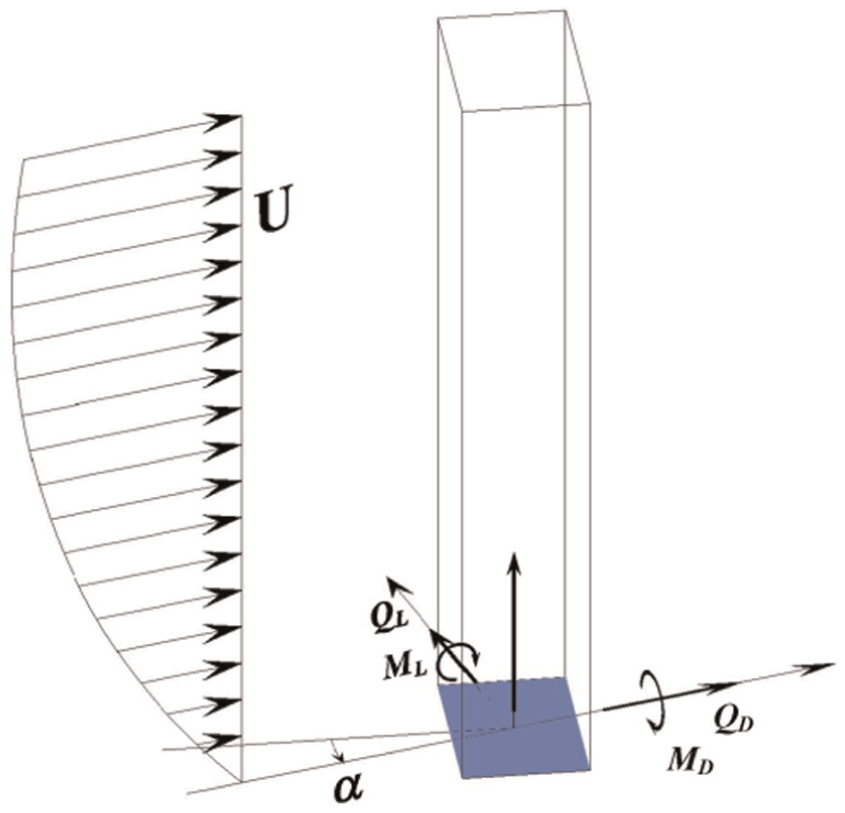
Base moment in across-wind and along-wind direction.
Suction wind tunnel experiment
Experimental model
The model used in the test was a CAARC standard high-rise building model, whose prototype size is 30.48 m (width) × 45.72 m (length) × 182.88 m (height). The building is slender with a height to width ratio of 6. The scale ratio of the model in the test is 1:150, which is shown in Figure 2.

CAARC model: (a) prototype (m) and (b) experiment model.
The material of the model is 6-mm-thick Plexiglas with a smooth exterior surface and sharp edges. The stiffness of the model is sufficient to prevent deformation and vibration at wind speeds up to 10 m/s. The layout of the pressure taps and circular suction holes are shown in Figure 3. The diameter of a suction hole is 1 cm. There are 245 pressure taps on the model with 45 pressure taps on the top and 200 pressure taps on the four sides. Because of the symmetry of the model, suction holes are only arranged on surface f1 and surface f2. There are three vertical lines of suction holes on surface f1 and one vertical line on surface f2. Each line has four suction holes and stands for a corresponding suction mode. Therefore, the four suction modes K1, K2, K3, and K4 are given from left to right as shown in Figure 3. A suction mode works by opening only this line of suction holes.
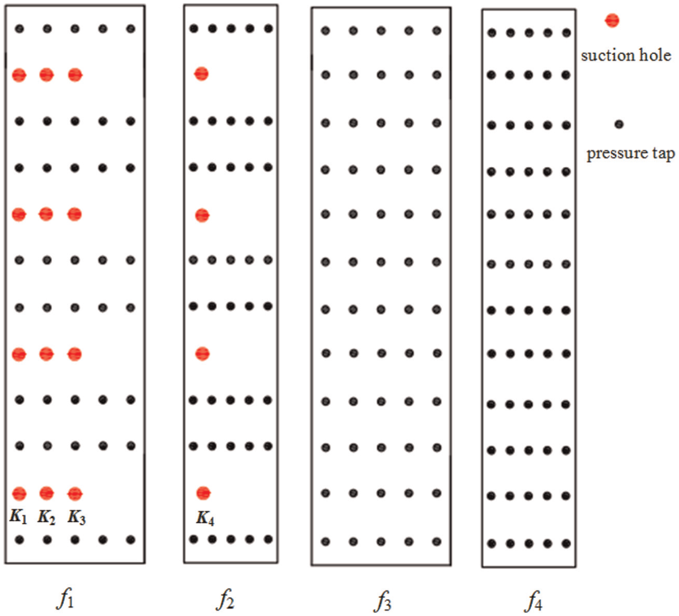
Arranges of the pressure taps and the suction holes on the CAARC model.
The wind tunnel experiment environment
The experiment was conducted in an atmospheric layer wind tunnel at Harbin Institute of Technology with a laminar flow section of 25 m in length, 3 m in height, and 4 m in width. The blockage ratio of the model is approximately 3%. C-class terrain roughness category (Chinese wind load codes) was chosen in this wind tunnel experiment with a power-law exponent of 0.22. Figure 4 shows the velocity profiles (U(z) = v(z/H)0.22, where U(z) represents the wind speed at the height z and v = U(H)) and wind-velocity power spectral density (PSD) measured in the wind tunnel. In Figure 5, n is frequency and
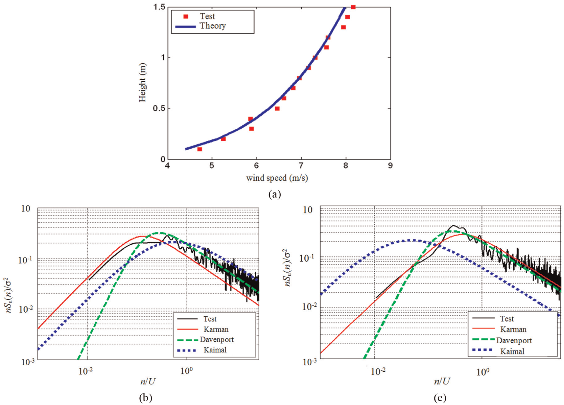
Wind-velocity profiles and wind-velocity PSD: (a) velocity profiles, (b) height = 100 mm, and (c) height = 1000 mm.
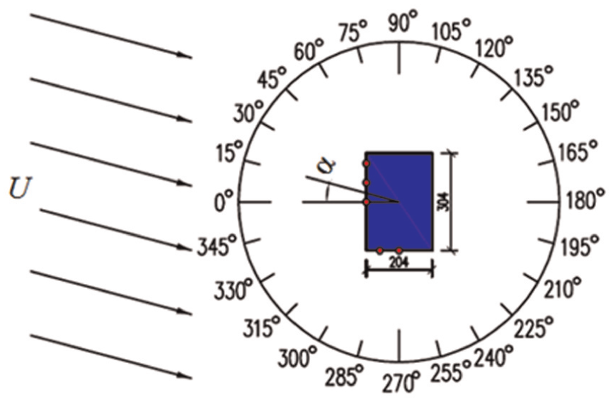
Sketch of the wind incidence angles (unit: mm).
A suction device with a maximum inflow capacity of 20 L/min was employed in the experiment. During pressure measurement, the signal sampling frequency was 312.5 Hz, and sampling time was 32 s.
Experiment work condition
The inflow wind incidence angle for the model is shown in Figure 5. In the wind tunnel test, the wind speed was 8 m/s, and the suction flows applied were 10, 13, 16, and 19 L/min.
Experimental results and analysis
SBMR (η)
The mean and fluctuating bottom shear force and moment without suction in the across-wind direction are shown in Figure 6. In the figure, 0.5ρv2 is the dynamic pressure at the top of the model, ρ is the air density, QL is the bottom shear force in weak axis direction, M is the base moment in weak axis direction, and B is the width of the windward surface. The results agree well with Obasaju (1992). It shows that the base moment change with wind incidence angle has a very similar tendency to that of the base shear force, from the viewpoint of both the mean and fluctuating values. The mean value has an inverse tendency with the fluctuating value from the viewpoint of the base moment and the base shear force. In this model, 0° and 180° are the key wind incidence angles for mean base moments, and 90° and 270° are the key wind incidence angles for the fluctuating base moments.

The mean and fluctuating bottom shear force and moment without suction: (a) the mean base shear force, (b) the mean base moment, (c) the fluctuating base shear force, and (d) the fluctuating base moment.
Under suction modes K1, K2, K3, and K4, the SBMR results of the model in weak axis direction are shown in Figure 7. Apparently, suction coefficients have no influence on the control effect of steady suction, which may attribute to the little change of flux between each case. It also shows that the SBMR results under the four suction modes are all about 1.0, implying that the effect of suction on reducing along-wind loads is not obvious. However, for a wind incidence angle equal to 0°, the SBMR results under K3 and K4 are all about 0.9, indicating a little reduction in mean wind loads.
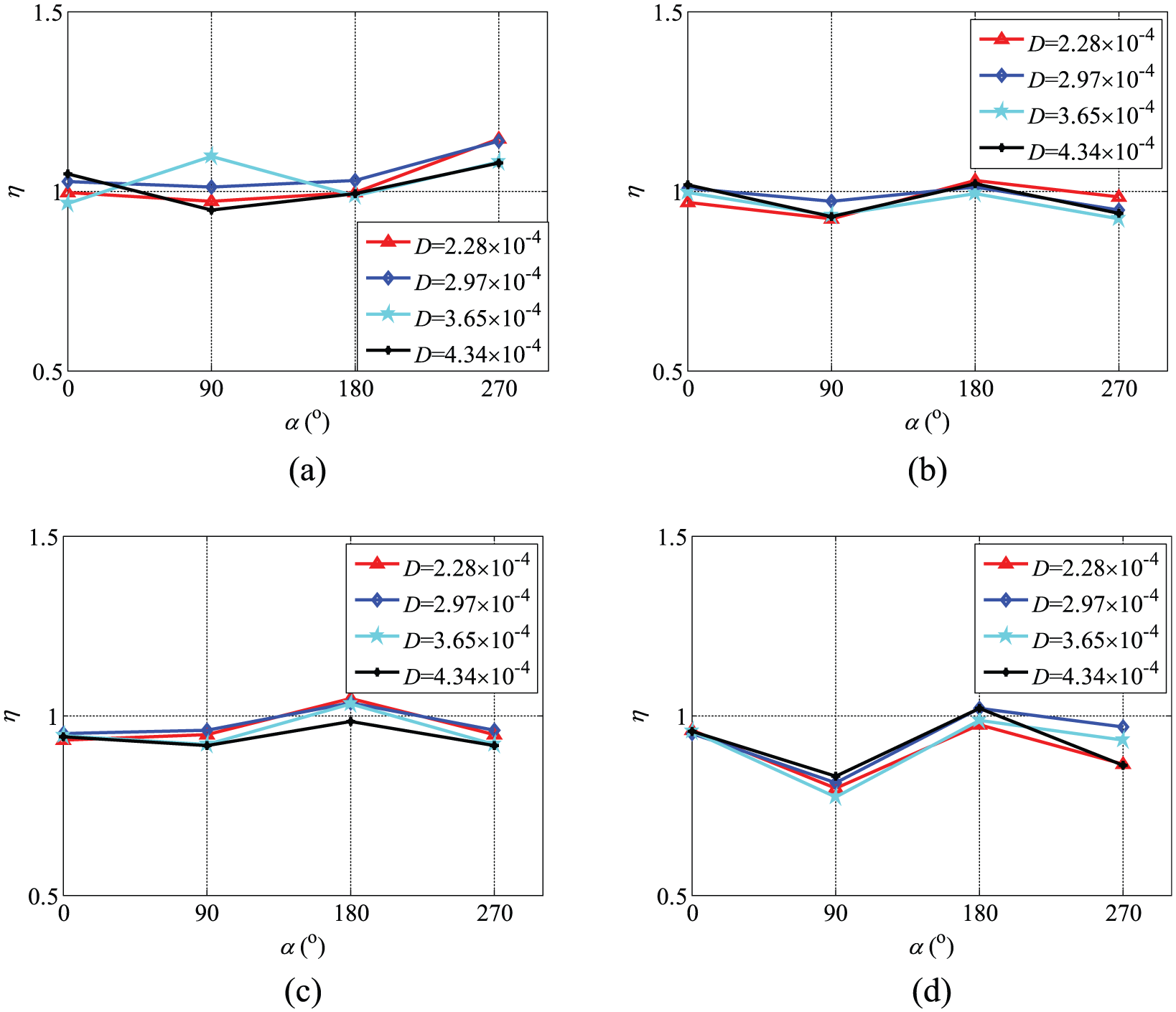
SBMR of the model under different wind incidence angles: (a) K1, (b) K2, (c) K3, and (d) K4.
FBMR (ση) and PSD
The changes of FBMR in weak axis direction are shown in Figure 8.
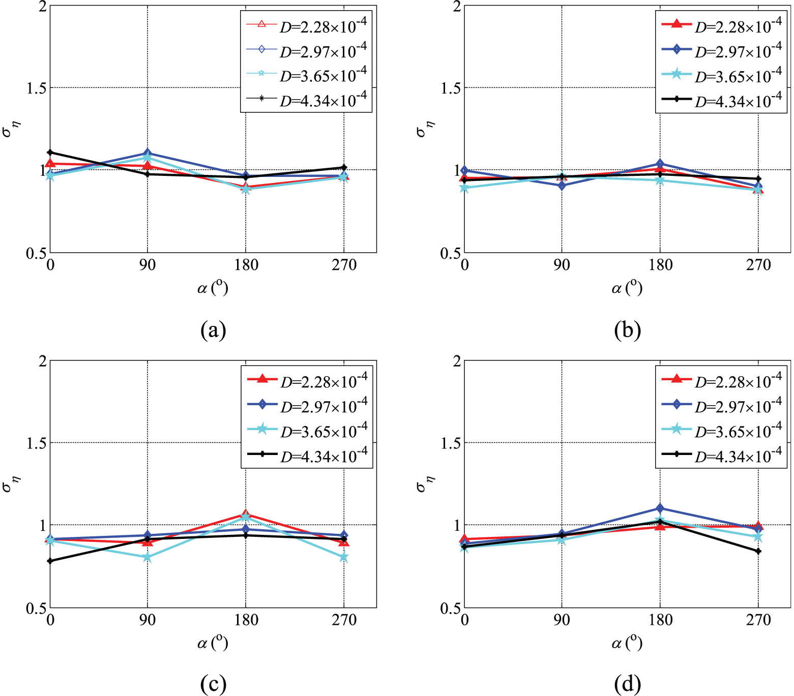
FBMR under different wind incidence angles: (a) K1, (b) K2, (c) K3, and (d) K4.
When the wind incidence angle is 90° or 270°, compared with K1, and K2, the minimum FBMR value reaches 0.8 under K4 and K3. Therefore, steady suction arranged in the middle of the windward surface or the rear surface close to sharp edge of the model effectively reduces the fluctuation of wind loads when wind blows straight on the narrow side. As is known, in this situation, the regular vortex shedding may the main reason inducing the fluctuating wind loads, steady suction arranged at specific place could disturb or destroy the spanwise vortices and hence reduce the fluctuating wind loads.
The PSD of bottom moments of the model in the weak axis direction is shown in Figure 9, and the bottom moments are normalized by 0.5ρv2BH2, where 0.5ρv2 is the velocity pressure at the top of the model, B is the width of the model, and H is the model height. Figure 9(a) shows that as the wind incidence angle is 0°, the peak value of the PSD under K3 and K4 is lower than the values under the others. In addition, when the wind incidence angle is 90°, the sharp peaks observed under K3 are smaller than those under the others in Figure 9(b), which implies that the effect of vortex shedding on the fluctuation of across-wind loads is reduced and confirms the expected reason above.
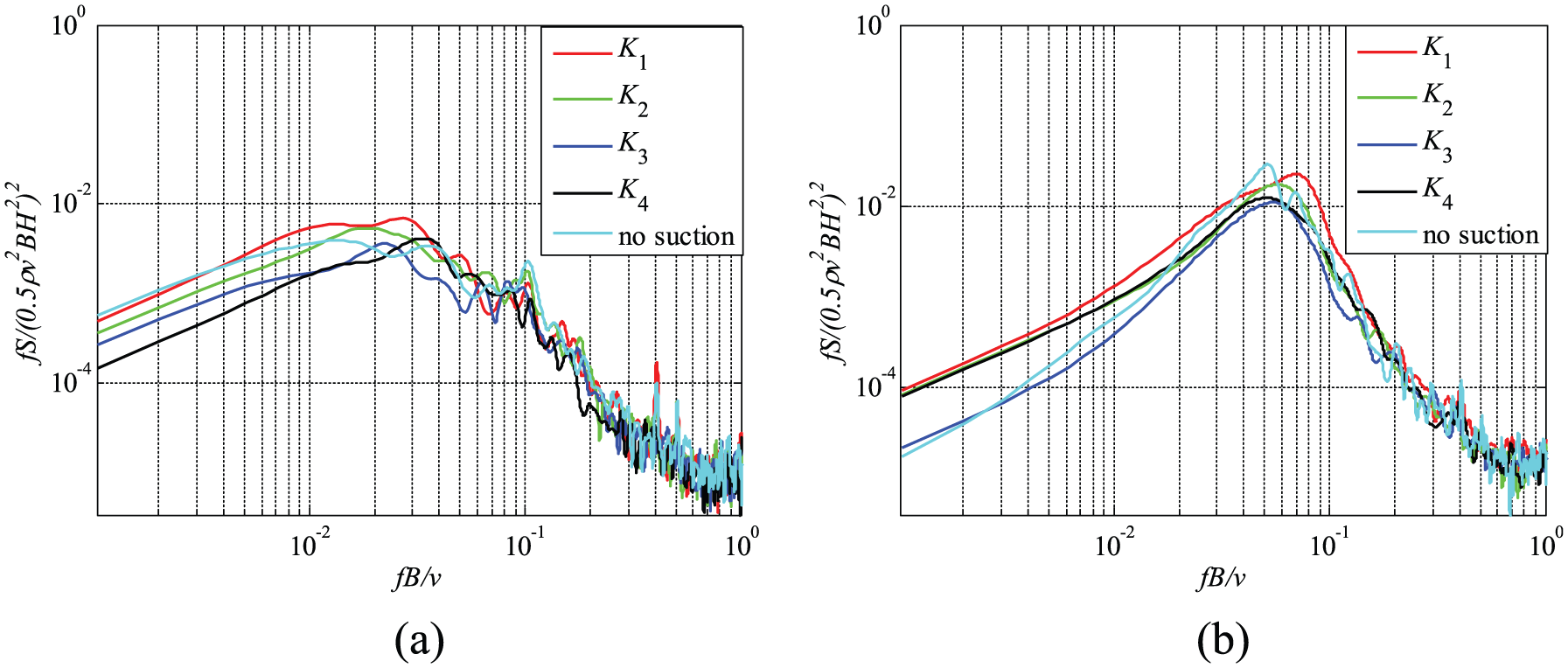
PSD of the building model suction moment in weak axis direction: (a) α = 0°
Vertical distributions of wind forces
The wind forces at different heights on the model in the weak axis direction are shown in Figure 10.
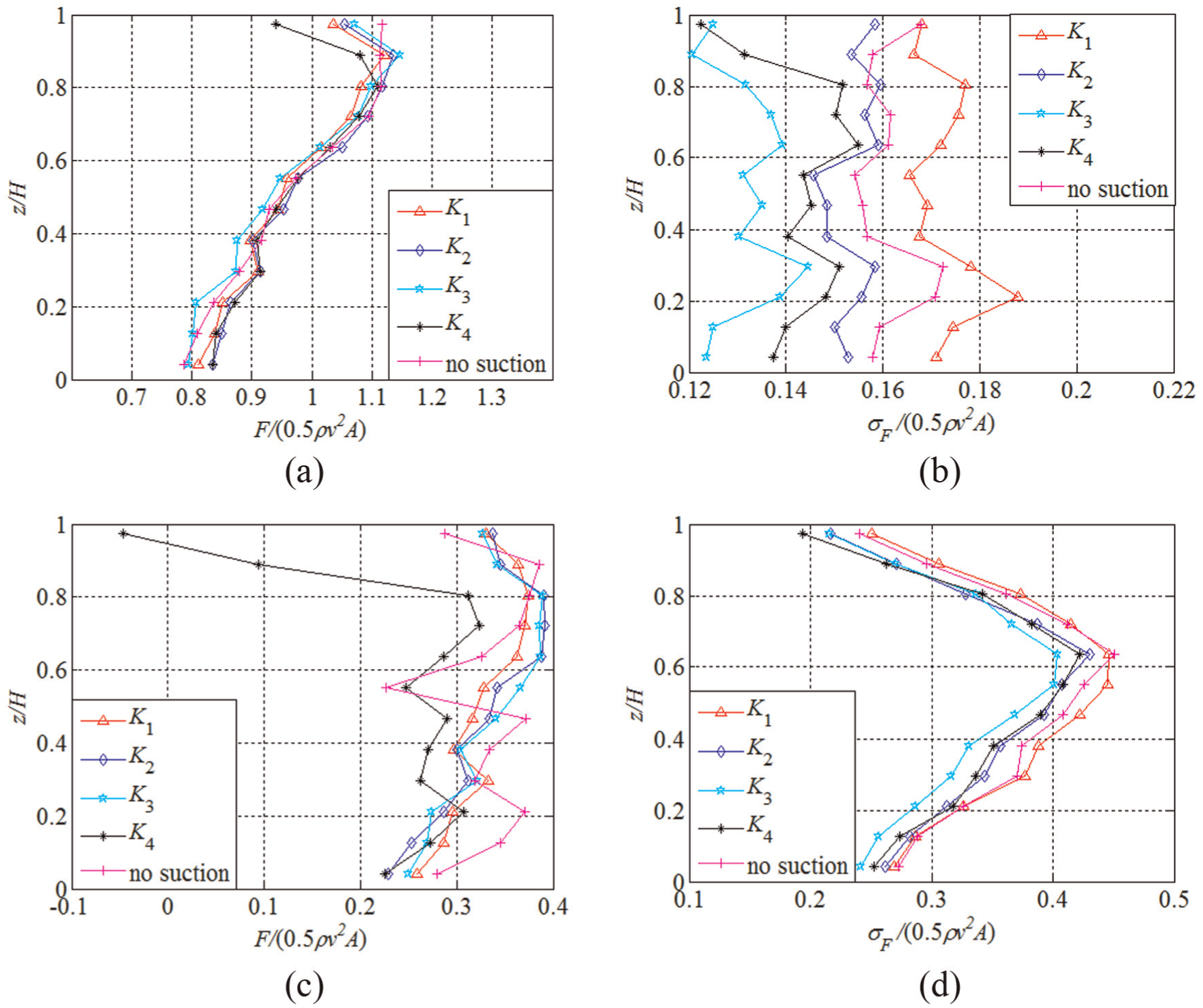
Vertical distributions of wind force
In Figure 10, F is the mean wind force at a certain height, σF represents the RMS of F whose mean value is negligible, and A is the influence area of that height. Figure 10(a) shows that the distributions of the mean wind force have almost no difference between steady suction and no suction when the wind incidence angle is 0°. In Figure 10(b), under K3, the RMS values are smaller than those under the other suction modes along the height of the model when the wind incidence angle is 0°. When the wind incidence angle is 90°, under K4, the wind forces are significantly smaller than those under the other suction modes along the height of the model, especially above 0.8H as shown in Figure 10(c). At the same wind incidence angle, K3 has the smaller RMS values of wind forces compared with the others at most of the levels of the model, as shown in Figure 10(d).
When wind blows straight on the wide side, steady suction in the middle of the windward surface efficiently reduces fluctuation of wind forces in the weak axis direction along the height of the model. When wind blows straight on the narrow side, steady suction at the edge of the leeward surface remarkably reduces the mean wind force in the weak direction at almost every level of the model. When wind blows straight on the narrow side, steady suction in the middle of wide side effectively reduces fluctuation of wind force in the weak direction at most of levels of the model. All the above results indicate that the control effect of steady suction is immune to end effect (tip vortex induced effect) and ground effect.
Distribution of mean and fluctuating pressure coefficients
The distribution of mean and fluctuating pressure coefficients on f1–f4 surface are present in Figure 11.
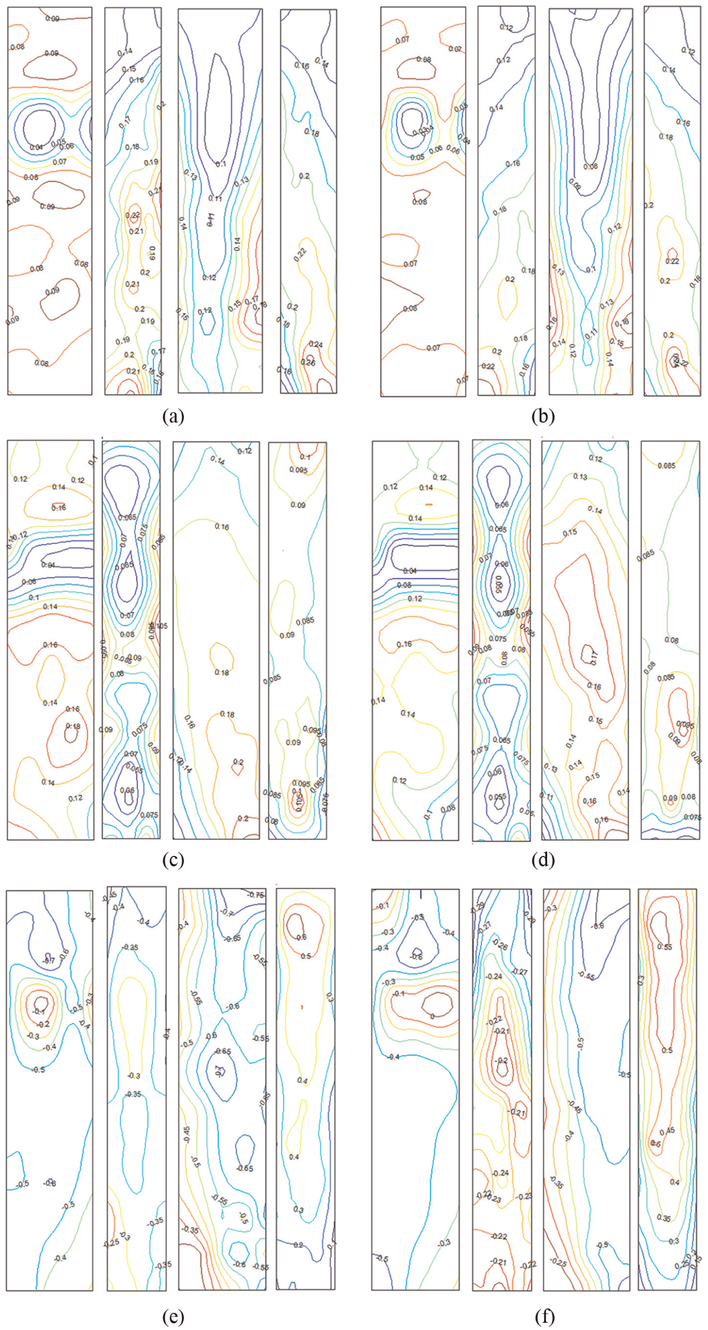
Mean and fluctuating wind pressure coefficients
Figure 11(a) and (b) shows that with a wind incidence angle of 0°, under suction (K3), fluctuating wind pressure coefficients on each surface are smaller than without suction Figure 11(c) and (d) shows that under suction (K3) and with a wind incidence angle of 90°, the fluctuating wind pressure is smaller than that under no suction. This may be because suction flow disturbs vortex shedding. As shown in Figure 11(e) and (f), under suction (K4), the mean wind pressure coefficients on each surface are smaller than without suction. This may be due to flow separation being suppressed by the steady suction. In conclusion, suction arranged in the middle of windward surface efficiently reduces fluctuating wind pressure when wind blows straight on wide side. Furthermore, suction arranged in the middle of wide side efficiently reduces fluctuating wind pressure of the four surfaces, when wind blows straight on the narrow side surface. Finally, suction arranged in the edge of leeward surface efficiently reduces the mean pressure of the four surfaces, when inflow blows straight on the narrow side surface.
Steady suction control on actual super-tall buildings
Because steady suction is an active aerodynamic control, it needs a momentum injection (i.e. suction flow) and the corresponding driven system. Achieving a desired momentum injection for actual tall buildings could be internally driven, either by exhaust air of the heating, cooling, and ventilation system (HVAC) or by compressed air lines located at the corners of the building if the momentum of the suction flow meets the requirements (Menicovich et al., 2014). Otherwise, it could be externally driven by the addition of an auxiliary suction system. Floor space is necessary for the placement of an auxiliary suction system. Because of the high yield potential in both commercial and residential real-estate markets, the floor space occupied by the system should be as small as possible. The mechanical floor, a commonly used story of a high-rise building that is dedicated to mechanical and electronics equipment, could be used to place the auxiliary suction system. In addition, as a rule of thumb, super-tall buildings require a mechanical floor for every 10 tenant floors (10%), and this exactly meets the requirement of the distance between two suction holes, at least in this article.
Conclusion
The synchronization pressure test was conducted in the wind tunnel at Harbin Institute of Technology. A CAARC test model was equipped with suction holes and subjected to a series of tests to determine the efficiency of steady suction for controlling wind loads. Based on our analysis of the results, we have made the following conclusions:
Steady suction has little control effect on reducing the mean wind loads in direction of weak axis.
It is because the suction flow could disturb or destroy the spanwise vortex shedding. When wind blows straight on the narrow side, steady suction arranged in the middle of wide side or close to sharp edge at the rear surface is effective in reducing the fluctuation of the wind loads in weak direction.
Steady suction can reduce fluctuation of wind forces in the weak axis direction along the height of the model, which indicates that the control effect of steady suction is immune to end effect (tip vortex induced effect) and ground effect.
Footnotes
Declaration of Conflicting Interests
The author(s) declared no potential conflicts of interest with respect to the research, authorship, and/or publication of this article.
Funding
The author(s) disclosed receipt of the following financial support for the research, authorship, and/or publication of this article: The support for this work is provided in part by the National Natural Science Foundation of China (Grant No. 51378163), postdoctoral science-research developmental foundation of Heilongjiang Province (Grant No. LBH-Q13077), and the Fundamental Research Funds for the Central Universities (Grant No. HIT. NSRIF. 2015100). In addition, the work was performed in the Joint Laboratory of Wind Tunnel & Wave Flume at the School of Civil Engineering, Harbin Institute of Technology, in China.