
Abstract
High-strength concrete is becoming very popular around the world due to its many advantages over normal-strength concrete. There are significant behavioural differences between high-strength concrete and normal-strength concrete, most notably the brittleness and sudden spalling under elevated temperatures, whereby pieces of hardened concrete explosively dislodge. Although all high-rise and even many medium-rise buildings have high-strength concrete walls, the spalling of high-strength concrete walls in fire has generally been ignored by the designers and the fire resistance of walls has been calculated using the rules specified for normal-strength concrete. Catastrophic failures could occur due to this ignorance of an important issue. Major design codes including the American and Australian Codes do not cover spalling adequately. Even the Eurocode rules are based on limited research. After a brief discussion on the present design practice, this article presents a summary of spalling research. The relevant results from a comprehensive study conducted at the University of Melbourne are briefly discussed. The authors are not aware of any other comprehensive research projects covering the fire behaviour of normal-strength concrete and high-strength concrete walls exposed not only to standard fires but also hydrocarbon fires. The results showed that spalling in high-strength concrete is more significant when subjected to hydrocarbon fire compared to normal-strength concrete. The level of compressive load on the panels was also found to have a significant effect on the fire performance of the high-strength concrete panels. The finite analysis element program, ANSYS, was used to model the concrete walls subjected to load and fire (both ISO834 Standard fire and hydrocarbon fire). The test results were used to validate the computer model.
Introduction
Due to the increased incidence of accidental fires, explosions and the trend to build high-rise structures, the performance of concrete structures in fire has become increasingly significant in the past decade. The types of fires evident have exceeded the scope of standard fire tests and, in many recent events, are those of the hydrocarbon type (Ngo et al., 2013). There is an increasing use of load-bearing reinforced high-strength concrete (HSC) walls in the design of buildings. The increase in HSC (f′c > 50 MPa) use is because it has many advantages and it has also become easier to manufacture, due to the availability of a variety of pozzolanic admixtures such as micro-silica and high-range super-plasticisers (Ta, 2010). The reason for the popularity of using HSC walls is mainly due to the trend towards reinforced concrete core walls and other lateral load resisting walls in medium-rise and high-rise buildings and the increased acceptance of tilt-up and other types of precast structures. In addition to providing a load-bearing function, these walls usually provide a fire separating function between compartments in modern structures, and they must therefore satisfy all three fire safety requirements, namely, integrity, insulation and structural adequacy, at high temperatures (Cement Concrete & Aggregates Australia (CCAA), 2010).
Despite the increasing use of load-bearing HSC walls in buildings, there have been only very few investigations reported on HSC walls subjected to fire conditions, both locally and internationally (Crozier and Sanjayan, 2000; Mendis, 2003; Ngo et al., 2013; Ongah et al., 2003).
Fire resistance of HSC
According to the wide-ranging research studies conducted by the authors and the other researchers, over a number of years, the material properties of HSC vary differently with temperature as compared to those of normal-strength concrete (NSC) (Ali, 2002; Castillo and Durrani, 1990; Kodur, 2008; Phan, 2008; Ting et al., 1992). Meda et al. (2002) have studied the ultimate behaviour of HSC sections at high temperature and after cooling subjected to several fire durations. They concluded that HSC sections are more temperature-sensitive than NSC sections. Results indicated that losses in relative strength due to high-temperature exposure were affected by the test condition and w/c ratio, but there were significant interactions among other main factors that resulted in complex behaviours (Phan, 1996). These complex behaviours were believed to be linked to heat-induced transformations and transport of capillary/physically bond and chemically bond water. The differences are more pronounced in the temperature range of between 25°C and about 400°C, where higher strength concretes have higher rates of strength loss than lower strength concretes. These differences become less significant at temperatures above 400°C. Compressive strengths of HSC at 800°C decrease to about 30% of the original room temperature strengths (Phan, 1996). The difference between the compressive strength versus temperature relationships of normal weight and lightweight aggregate appears to be insignificant, based on the limited amount of existing test data. The tensile strength versus temperature relationships decreases similarly and almost linearly with temperature for HSC and NSC. HSC mixtures with micro-silica have higher strength loss with increasing temperatures than HSC mixtures without micro-silica (Ali, 2002). The failure of HSC is more brittle than NSC at temperatures up to 300°C (Ngo et al., 2013). With further increase in temperature, specimens exhibit a more gradual failure mode.
Adverse effects of HSC elements in fire have been identified by researchers (Mendis, 2003; Sanjayan, 2011). According to the results of laboratory-focused fire tests, there are remarkable differences between the properties of HSC and NSC in terms of the loss of cross-section, the timing of loss of strength, and the degrees of deformation and spalling at elevated temperatures. The most notable finding is that HSC is considered to suffer more seriously from spalling due to fire than NSC. Fire-induced spalling of concrete is a phenomenon whereby pieces of hardened concrete explosively dislodge or fall-off the fire-exposed surface of a concrete member during rapid high-temperature exposure. The risk of concrete spalling at elevated temperature should be considered when designing structural elements especially HSC (f′c > 50 MPa). Disintegration of concrete parts due to spalling can cause serious reduction in the cross-section of structural elements and could lead to early catastrophic failure. The depth of spalled concrete often far exceeds the cover to the main reinforcement. The pieces can be large or small and detachment can either occur explosively or pieces may dislodge and subsequently fall due to moisture clog and the stresses exceeding the tensile strength (Figure 1). The pore pressure generated during fire exposure in typical HSC columns can reach about 4.5 MPa, while the corresponding pore pressure in conventional NSC columns is only about 1 MPa (Kodur et al., 2013). Spalling can take place over the whole surface area of a member or in localised areas. The risk of spalling is higher in HSC due to the following reasons:
Low permeability of HSC retains the moisture inside the concrete resulting in a high moisture content being present for prolonged periods.
Low porosity of HSC creates higher pore pressure.
HSC tends to be subject to higher compressive stresses than lower strength concrete.

Moisture clog model for spalling of concrete (Shorter and Harmanthy, 1961).
Whether or not spalling occurs in a particular situation and the extent of spalling are random in nature. Therefore, although the investigations on HSC started in mid-1990s, still no comprehensive design rules are included in design codes. HSC specimens heated at higher heating rates, such as hydrocarbon fire which occurred in World Trade Center collapse on 11 September, and larger specimens are more prone to spalling than specimens heated at lower rates and of smaller size. Ta (2010) has showed that, for HSC, hydrocarbon fire produces explosive spalling compared to standard fire.
Noguchi et al. (2011) have investigated the spalling properties of concrete in relation to surface moisture content. They found that spalling of HSC was significantly affected by moisture transfer in the surface region of concrete and moisture transfer was found to be closely related to the temperature profiles resulting from the characteristics of pore structures, which are the main passages for moisture. They also found that in HSC (80 MPa), the probability of spalling and scale of damage could be reduced according to dryness in the surface region (0–30 mm depth).
There are some general observations on spalling (CCAA, 2010; Ngo et al., 2013; Sanjayan, 2011), summarised below:
The tendency for spalling is high when
The element is made of HSC rather than NSC;
Cover to reinforcement is increased, especially more than about 40 mm;
Moisture content of the concrete is high;
The temperature rise of the fire is rapid and concrete is subjected to a high thermal gradient;
Concrete is subjected to compressive stress;
The concrete is subjected to a hydrocarbon fire compared to a standard fire.
Many experimental studies (Ngo et al., 2013) have shown that the use of polypropylene (PP) fibres in the concrete mix reduces the tendency for spalling. This is due to the fact that the PP fibres melt during the fire, thus increasing the internal voids of the concrete and decreasing the vapour pressure build-up within the concrete. A dosage rate of 1.2 kg/m3 of 6-mm monofilament PP fibres is recommended in Ali (2002) to reduce the level of spalling, although EN1992-1-2 2004 recommends a higher dosage, as stated below.
Rules for HSC in Eurocode
Although not proven by systematic testing, the rules given in Section 6 of EN1992-1-2 2004 can be used as an initial guide for HSC. Strength properties are given in three classes (f′c, 50–70 MPa, 70–90 MPa and equal to 90 MPa), and recommendations against spalling are given for two ranges of HSC. Where the actual characteristic strength of concrete is likely to be of a higher class than that specified in design, the relative reduction in strength for the higher class should be used for fire design.
The Simplified Calculation Method presented in the following paragraph (500° isotherm method, zone method, curvature method) can be applied for HSC with some modification factors.
The following four methods are suggested for spalling:
For concrete strengths between 55 and 80 MPa, fire design rules provided for NSC apply if the maximum content of silica fume is less than 6% by weight of cement. For higher contents of silica fume, the rules given in (2) apply.
For concrete strengths between 80 and 90 MPa (and can be assumed to extrapolate up to 100 MPa), spalling can occur in any situation for concrete exposed directly to the fire and at least one of the following methods should be provided:
Method A: A reinforcement mesh with a nominal cover of 15 mm. This mesh should have wires with a diameter ≥ 2 mm with a pitch ≤ 50×50 mm. The nominal cover to the main reinforcement should be ≥40 mm.
Method B: A type of concrete for which it has been demonstrated (by local experience or by testing) that no spalling of concrete occurs under fire exposure.
Method C: Protective layers for which it is demonstrated that no spalling of concrete occurs under fire exposure.
Method D: Include in the concrete mix more than 2 kg/m3 of monofilament propylene fibres.
Testing of NSC and HSC walls under standard and hydrocarbon fire
Previous research on concrete walls focused on standard fire testing only. Compared to a standard fire, a hydrocarbon fire creates a significant increase in temperature in the initial period of the fire (i.e. it reaches 1000°C in only 8 min). As a result, hydrocarbon fires could have the potential to create violent explosive spalling in concrete structures, especially in HSC. The results from fire tests on 10 reinforced concrete wall panels subjected to both standard or hydrocarbon fires, conducted in a PhD project at the University of Melbourne, are briefly discussed here. Four walls were of NSC, two of which were axially loaded at an eccentricity of 10 mm and two with no load, and exposed to both types of fires. Four identically dimensioned HSC walls were also tested using these variables. A further two HSC walls with PP fibres (2 kg/m3) added were tested under hydrocarbon fire. The water/binder ratio was maintained to be 0.59 for NSC mixes and 0.24 for HSC mixes. Specimens of NSC group or HSC group were cast in the same day to ensure the consistency of the water/binder ratio within each group. General-purpose Portland cement was used for both NSC and HSC mixes; 10% amorphous micro-silica was used for HSC specimens. Emphasis was given to observing the failure mode, spalling characteristics, thermal transfer and wall displacements. Initial moisture content of aggregates and slump was also measured.
Five specimens of 2400 mm×1000 mm×150 mm (height×width×thickness) were prepared. The composition of each specimen is presented in Table 1. Cylindrical specimens were also cast for the 28-day compressive strength test. Reinforcement was placed in two layers in both vertical and horizontal (N16@300 mm) directions, with clear cover of 25 mm. All walls were tested in a vertical position in a large furnace, and supported top and bottom only. Full-scale fire tests were done with a constant eccentric load of approximately 15%–20% of axial load capacity. The loading device consisted of 1000 kN (224.81 kips) hydraulic jacks mounted on top of the chamber and transferring the load through a steel beam to the top of the wall. Temperatures inside the specimens were measured every minute. Crack propagation, deflections and the occurrence of spalling were monitored during fire testing via four small portal openings on the furnace. Thermocouples were secured into specimen at designed locations as illustrated in Figure 2. Two different test conditions of standard fire (ISO834) and hydrocarbon fire were applied to the relevant specimen as given in Figure 3.
Moisture content, compressive test and loading details of specimens.
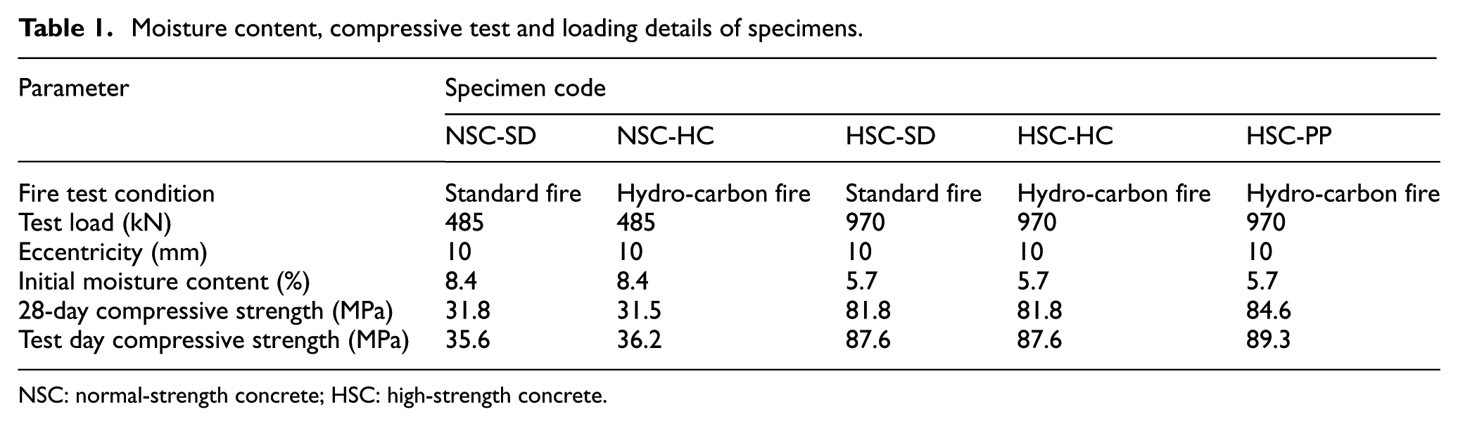
NSC: normal-strength concrete; HSC: high-strength concrete.
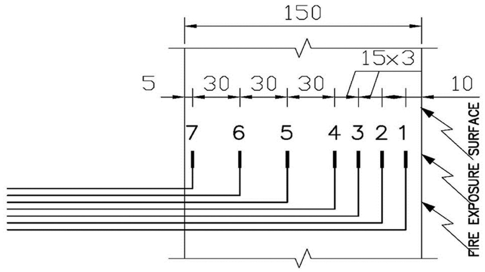
Positions of thermocouples through the specimen thickness (dimensions in mm).
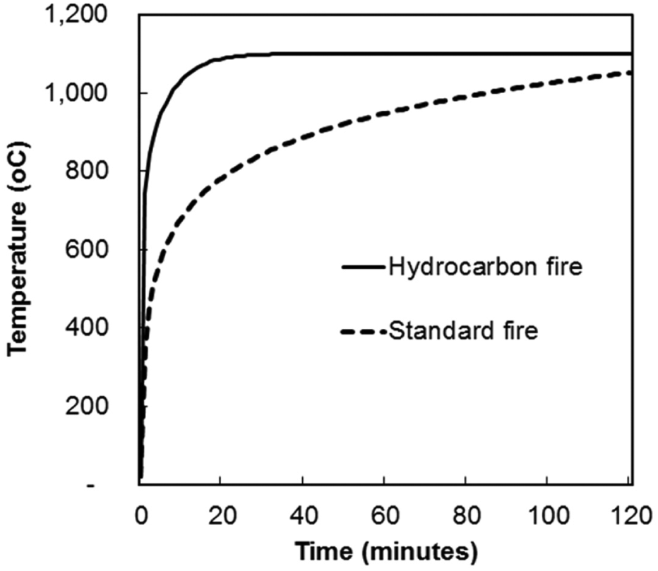
Standard and hydrocarbon fire curves.
The temperature profiles were more significantly different when identical HSC and NSC walls were subjected to a hydrocarbon fire. Figures 4 and 5 show a comparison of heat transfer within NSC and HSC walls subjected to standard and hydrocarbon fire. Temperatures were taken throughout the thickness of the specimen as indicated in Figure 2. Figure 4(a) shows the temperature curves recorded at thickness respective to points 1, 2 and 3 in Figure 2. Figure 4(b) shows the temperature curves recorded at thickness respective to points 4, 5, 6 and 7 in Figure 2. Temperatures were measured throughout the thickness of the specimen as indicated in Figure 2. Figure (5a) shows the temperature curves inside the furnace and temperature recorded at thickness respective to point 1 in Figure 2; Figure (5b) shows the temperature curves recorded at thickness respective to points 2 and 3 in Figure 2; Figure (5c) shows the temperature curves recorded at thickness respective to points 4 and 5 in Figure 2; Figure (5d) shows the temperature curves recorded at thickness with respective to points 6 and 7 in Figure 2. In the HSC3 panel, serious spalling occurred in the first period of the fire test, resulting in the temperatures of layers 1, 2, 3 and 4 increasing very quickly. After observation, it was deduced these differences were primarily the result of the HSC panel suffering early severe spalling compared to the NSC in a hydrocarbon fire which has rapid temperature increases in early stages.
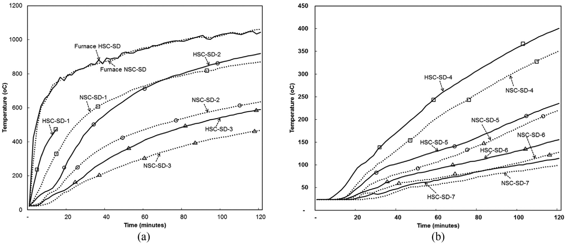
Comparison of heat transfer within NSC wall (NSC-SD) and HSC wall (HSC-SD) when subjected to standard fire.
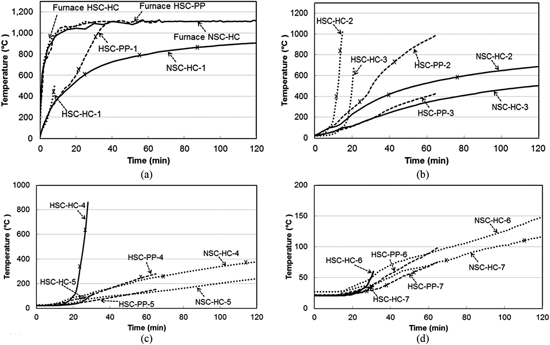
Comparison of heat transfer within NSC wall (NSC-HC), HSC wall (HSC-HC) and HSC wall with polypropylene fibre (PPF) (HSC-PP) when subjected to hydrocarbon fire.
After being subjected to 30 min of hydrocarbon fire, the HSC3 wall indicated severe spalling to a depth of more than 50 mm (Figure 6). In general, the temperatures at thermocouples 1, 2, 3, 4, 5, 6 and 7 of point T2 in specimen HSC were higher than in specimen NSC. The probable reasons for these differences are as follows: HSC suffers more from concrete spalling than NSC, HSC spalled earlier than NSC when the walls were subjected to fire, and the thermal conductivity of HSC is usually higher than that for NSC.

Depth of spalling of (a) NSC-HC (in mm) and (b) HSC-HC (in mm).
The results show that the spalling in specimen HSC 3 was significantly deeper than in specimen HSC 1 due to the hydrocarbon fire producing far more intense and greater spalling than a standard fire.
The results indicate that all concrete wall panels exposed to the standard fire tests survived the 120-min fire period, with low to moderate spalling evident. The NSC walls exposed to hydrocarbon fires also survived the 120-min test, whereas the HSC walls experienced severe spalling under these fire conditions (Figure 6(b)) with failure at 31 min. The addition of PP fibres in the concrete improved the fire resistance of HSC walls in hydrocarbon fire to 65 min.
This result was typical when comparing identical HSC and NSC test panels subjected to a standard fire test. The possible reason for the significant differences is that the HSC wall suffered more from early concrete spalling than its NSC counterpart and therefore was exposed to increased temperatures within its section at a much earlier time. Some form of spalling was found to occur within 3–25 min of the wall being exposed to fire and when the temperature at the spalling point was in the range of 200°C–400°C:
The experimentally observed time-temperature curves show that there is a reduction in the rate of temperature increase once the temperature reaches around 100°C up to approximately 130°C. This can be explained by the production of water vapour at 100°C, which requires energy to transform from liquid to gas. In addition, at this point, the water from the cooler inner layers travels to the outside layer, thereby reducing the heat energy at the outer layer.
The results show that specimen HSC walls (such as HSC 3) failed due to a loss in axial load capacity. There was a significant loss of cross-section at the point of fracture because of spalling. Therefore, the spalling of HSC (Figure 7) under extreme thermal loading (hydrocarbon fire) is the main factor in structural failure.

Spalling observed in the HSC specimens.
Observations on spalling are also applicable to HSC columns. Although not covered in this test program, it has been found that the combination of PP fibre and steel fibre (hybrid) exhibited the best performance for spalling reduction. The hybrid fibre reduced the spalling activity to minor non-explosive occurrence with the degree of spalling between 8.6% and 12.4% of the initial column weight. It is believed that this reduction can be attributed to the steel fibre resisting the initiation and expansion of cracks in the concrete matrix while the melting action of the PP fibre created micro channels in the concrete mass which alleviated vapour tension. Kodur et al. (2013) have concluded that spalling occurs only outside the reinforcement cage when the ties are bent at 135° into the concrete core. They also revealed that the extent of spalling is dependent on the type of aggregate, and spacing of ties. The degree of spalling is higher (100%) in the siliceous aggregate HSC than that for carbonate aggregate HSC (40%).
Modelling of concrete walls subjected to fire
The finite element analysis program, ANSYS, was used to model the concrete walls subjected to load and fire (both ISO834 Standard fire and hydrocarbon fire). The test results described in the previous section were used to validate the computer model. The results from the full spalling model and a comparison with the experimental results are given in this section. Spalling is considered by selectively deleting the spalled off elements. A simplified spalling model is adopted in the analysis. It is assumed that once the spalling occurred, the contribution from that element to the overall stiffness is insignificant.
The analytical models of concrete subjected to fire were developed and formulated in the following two steps to solve the coupled thermal-structural analysis:
Thermal analysis: heat transfer by conduction analysis, which models the heat transfer inside concrete structures for the surface thermal loading taken from an appropriate temperature versus time fire curve. In this analysis, surface temperatures were evaluated from the furnace temperature versus time curve through a proper heat-transfer model.
Structural analysis: This step models the structural response subjected to loads and heat fluxes taken from step (A).
The element Solid65 in ANSYS was used for the 3D modelling of reinforced concrete solids with reinforcing bars. The solid is capable of cracking in tension and crushing in compression. The element is defined by eight nodes having three degrees of freedom at each node. Translations are in the nodal x, y and z directions. Up to three different rebar specifications can be defined. The concrete is capable of cracking (in three orthogonal directions), crushing and exhibiting plastic deformation, and creep. For the selected type of elements, the rebars are capable of acting in tension and compression, but not in shear. They are also capable of plastic deformation and creep.
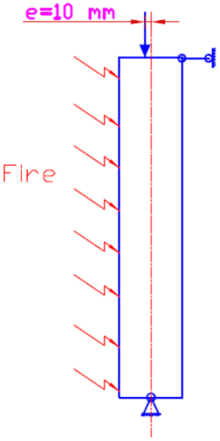
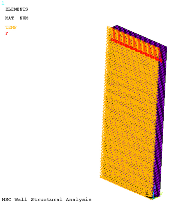
Three-dimensional models were constructed to represent the three-dimensional thermal transfer by conduction for the solid model. These models closely reflected the exact geometry and test conditions of the experimental thermal tests and were constructed to account for local effects in the thermal transducers. The models were used to predict the thermal transfer inside the concrete walls and the structural behaviour for standard fire and hydrocarbon fire curves given in the previous section. The wall was modelled with an eccentricity of 10 mm (Figure 8). Geometry of the concrete model is illustrated in Figure 9, which is a fine mesh of more than 24,000 elements.
Calculated structural model of concrete walls subjected to fire.
Model of concrete geometry, fire and eccentric load in ANSYS.
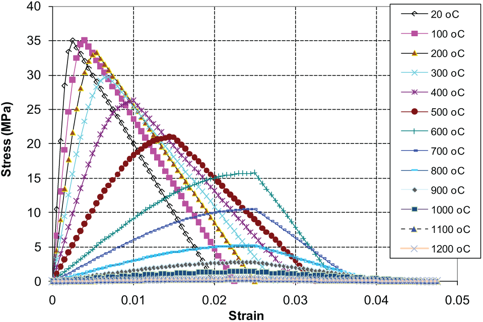
Eurocode 2 (2004) was used to model the stress–strain behaviour of concrete. Eurocode 3 (2005) was applied to the reinforcement steel. Typical curves for NSC and HSC are given in Figures 10 and 11.
Stress–strain curves for model NSC (35 MPa) walls at elevated temperature.

Stress–strain curves for model HSC (88 MPa) walls at elevated temperature.
Spalling was modelled by systematically deleting elements and following rules based on experimental observations as follows:
In the first period of time, from 2 to 35 min;
When the temperature exceeds 340°C;
Regions associated with the highest stress concentration, including a combination of thermal stress and axial load stress (60%–100% of total highest stress).
Only the high-strength concrete spalling model results and comparison with the experimental results are given here. All the comparisons are given in Shorter and Harmanthy (1961).
For the comparison given in the article, a finite element model of a HSC wall was subjected to a hydrocarbon fire and an axial load of 970 kN (eccentricity = 10 mm). In the first state, from 0 to 18 min, the model was run with all elements intact. At minute 18, layer 1 (25 mm thick) near the fire exposure surface reached 340°C. The model is then changed to state 2, in which all the elements in layer 1 were then eliminated. At 20 min, some of the elements at the middle part of the wall were observed to have a high total stress, and were eliminated. The stress results for the model at 20 min are shown in Figure 12.

Contour of 3D – stress of HSC wall subjected to hydrocarbon fire at 20 min.
At 24 min, some of the elements in the middle region of the wall exhibited a high total stress, and at the middle of the top and bottom parts of the wall, a high pore pressure was observed in the real tests. These elements were then eliminated. The results for the model at 24 min are shown in Figure 13.
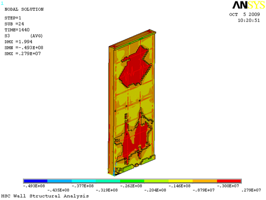
Contour of 3D – stress of HSC wall subjected to hydrocarbon fire at 24 min.
At 30 min, more of the elements in the middle region of the wall exhibited a high total stress and exceeded a temperature of 340°C. At the middle of the top and bottom parts of the wall, there was a high pore pressure observed and a temperature in excess of 340°C. They were gradually eliminated. The results of the model at 30 min are shown in Figure 14.

Contour of 3D – stress of HSC wall subjected to hydrocarbon fire at 24 min.
Figure 15 shows a comparison of the displacements between the model results and the test results of HSC3. The displacements of the concrete walls were measured at three points for each wall panel: D1, D2 and D3 (distance from the top of wall: 500, 1200 and 1900 mm, respectively). The model results almost match the test results, with difference values ranging from about 5% to 20%. Consequently, the spalling model can be assumed to predict the behaviour of an HSC wall subjected to hydrocarbon fire and axial load to a reasonably acceptable accuracy.

Comparison of displacements of model results and HSC3 test results.
Conclusion
Designers have to be aware of the fact that the HSC sections are more temperature-sensitive than NSC sections. A PhD project conducted at the University of Melbourne and other research reviewed in this article show that the behaviour of HSC walls subjected to ISO standard fire showed reasonably different thermal and structural characteristics when compared to NSC walls. Disintegration of concrete parts due to spalling can cause serious reduction in the cross-section of structural elements and could lead to early catastrophic failure. Whether or not spalling occurs in a particular situation and the extent of spalling have a random element in them. Therefore, major concrete standards do not cover specific design rules for spalling. Specifications in EN1992-1-2 2004 were summarised. Although not based on systematic research, these rules provide designers with some guidance. The increased use of HSC with concrete strengths more than 50 MPa has necessitated more dedicated research in this area. The spalling model results provide a good match with the experimental results, so the model can be used to predict the behaviour of HSC walls subjected to standard and hydrocarbon fire and axial load with some degree of confidence.
Footnotes
Declaration of Conflicting Interests
The author(s) declared no potential conflicts of interest with respect to the research, authorship and/or publication of this article.
Funding
The author(s) disclosed receipt of the following financial support for the research, authorship and/or publication of this article: The experimental work presented in the article was partially funded by the Vietnamese government and IBST and conducted as part of the PhD project of Dr Binh Ta. Their help is acknowledged.