
Abstract
To improve the mechanical performance of specially shaped reinforced concrete columns, which are widely applied in China, an innovative specially shaped composite column with high-strength concrete-filled steel tubular core was developed. To investigate the fire performance of this specially shaped composite column, two series of fire tests, including the fire resistance test series and the post-fire test series, were conducted on five full-scale specimens. The test parameters include the axial load level, the spacing of stirrups, and the fire exposure time. Compared to the test result of a controlled specimen that was axially compressed to fail without exposure to any fire, both the fire resistance under fire and the residual capacity after fire of this specially shaped composite column were analyzed and studied. The results indicated that the inner concrete-filled steel tubular core plays an important role in both the fire resistance and the post-fire performance, and that the post-fire residual capacities of three post-fire testing specimens were also largely increased.
Keywords
Introduction
In recent years, reinforced concrete (RC) columns with cross sections of special shape (L-, T-, and cross shapes) have been widely used in existing buildings in China. Compared with columns with rectangular cross sections, columns with specially shaped cross sections have the advantage of enlarging the useful indoor area in architectural design. Generally, columns with specially shaped cross sections have a larger surface area and have a thinner concrete cover than the normal RC column; hence, the damage of specially shaped columns under fire is more serious than that of the normal ones.
In the past decade, research has been concentrated on the fire performance of normal RC columns (Al-Salloum et al., 2016; Hwang et al., 2016; Raut and Kodur, 2011; Wu et al., 2010) or steel and composite columns (Abbas et al., 2017; Espinos et al., 2014; Won et al., 2016). In contrast, the research studies on the fire performance of specially shaped columns are limited. Wu et al. (2010) reported a study of 12 axially restrained RC columns with specially shaped cross section under fire conditions, as shown in Figure 1. Balaji et al. (2016) focused on the effect of the cross-sectional shape of the column on the fire resistance design and the predicted fire resistance capability of compression members using the finite element method and the temperature profiles, showing that the geometric shape and size of the column have significant effects on the fire resistance. Hence, a detailed study is necessary to determine the fire rating of columns of complex geometric shape.

Representative cross sections: (a) cruciform RC column and (b) internally confined hollow RC column.
In particular, despite the research studies on the fire performance of concrete-filled steel columns (Choi et al., 2012; Han et al., 2015; Ibañez et al., 2015), few studies (especially experimental studies) concentrated on the performance of an inner steel core filled RC column. Considering the poor ductility caused by the brittle failure of the inner face of the column, Kang et al. (2008) used an inner tube to reinforce the inner face of a hollow RC column. Won et al. (2014) conducted a study of the fire resistance performance of a steel composite hollow RC column with an inner tube under ISO 834 standard fire and found that the fire resistance performance of an internally confined hollow RC column decreased as the thickness of the inner tube decreased, that is, the inner tube has a significant influence on the fire resistance of the hollow RC column; the typical cross section of an internally confined hollow RC column is plotted in Figure 1.
To increase the fire performance of specially shaped RC columns, a type of concrete-filled steel tubular (CFST) core was introduced; thus, a specially shaped composite column with CFST core was formed (Xu et al., 2007). Compared to normal specially shaped RC columns, this new type of specially shaped composite column has much higher axial bearing capacity and deformation capacity because of the high-strength concrete in the CFST core. Because the steel tube core is encased inside concrete, the corrosion issues can be effectively solved, and the fire performance can be largely improved. Additionally, local buckling of the steel tube can be effectively avoided. Hence, compared to the specially shaped RC columns and the CFST columns, this type of specially shaped composite columns substantially improves both the fire resistance and the post-fire performance.
Therefore, it is essential to investigate the performance of this type of specially shaped composite column both under fire and after fire. This article outlines the experimental program and presents the experimental results of six full-scale cross-shaped composite columns with high-strength concrete CFST cores conducted recently; the performances were sorted according to the results of the fire resistance test series and post-fire test series and were compared to a control specimen tested under ambient temperature. The temperature of fire test furnace was strictly controlled according to ISO-834 standard curve to simulate a real fire.
Test specimens
Parameters and specifics of the six specimens studied are listed in Table 1. In the definition of the specimen labels, the first two letters denote the name of the series: FR denotes fire resistance test series, and PF denotes post-fire test series. For the fire resistance series, the last three digits in the label indicate the spacing of the stirrups of the specimens. For the post-fire test series, the last three digits indicate the time of exposure to fire. The controlled specimen was named NF-000. All specimens were designed to be axially loaded and burned in all four faces.
Summary of the specimen parameters and the test results.
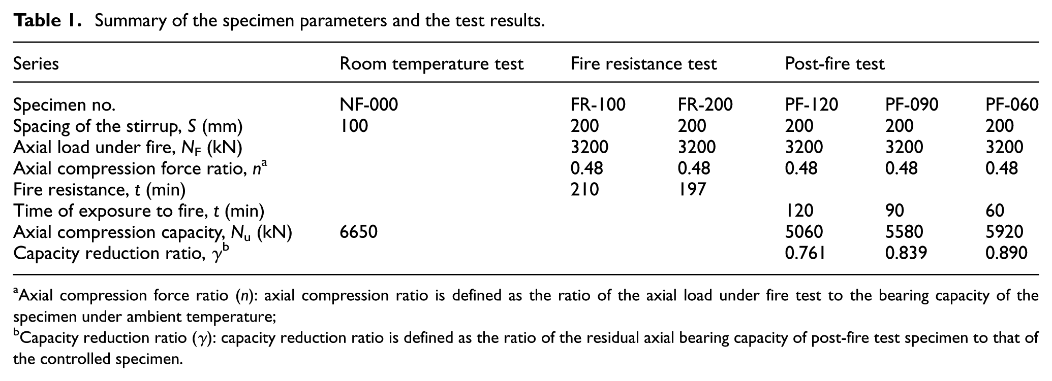
Axial compression force ratio (n): axial compression ratio is defined as the ratio of the axial load under fire test to the bearing capacity of the specimen under ambient temperature;
Capacity reduction ratio (γ): capacity reduction ratio is defined as the ratio of the residual axial bearing capacity of post-fire test specimen to that of the controlled specimen.
All six specimens were composed of three parts, that is, one middle part and two enlarged ends and were the same in the cross-sectional shape and dimensions; Figure 2 shows the elevation and cross sections of the specimens. All six specimens were 3770 mm in length, and the middle part was crisscross in shape, composed of one inner center and four outer limbs. Two enlarged ends of the specimens were square in shape, with dimensions of 500 × 500 mm2 in cross section and 300 mm in height and were connected to the base of the fire test furnace and the load cell by bolts and steel connection plates, respectively.

Details of the test specimens: (a) elevation of specimens, (b) 1-1 section, (c) 2-2 section, and (d) 3-3 section.
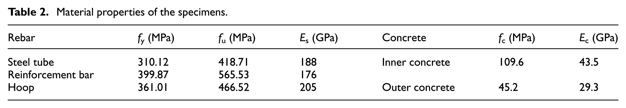
All columns were reinforced with 12 longitudinal bars, each with a diameter of 16 mm; the percentage of longitudinal bars to the total cross-sectional area of the specimens was 1.51%. These bars were tied using stirrups, each with a diameter of 8 mm, and the spacing of the stirrups in the middle part of the specimen FR-100 was 100 mm, and that of other specimens was 200 mm. The steel tube of the CFST core was made of common Q235 grade steel, and the percentage of the area of the steel tube to the total cross-sectional area of the specimens was 0.86%. A schematic diagram of the reinforcement and some key parameters of the specimens are shown in Figure 3 and Table 1, respectively. The mechanical properties of the materials measured experimentally during the test day are summarized in Table 2.

Schematic diagram of reinforcement of the specimens.
Material properties of the specimens.
Type-K (nickel chromium–nickel silicon) thermocouples labeled WRNK-101K thermocouples were installed at the mid-height of the middle part of each specimen to measure the internal temperature, thermocouples no.1 to no.5 were installed in concrete, and thermocouple no.6 was placed on the outer surface of the steel tube; Figure 4 shows the locations of the thermocouples within the cross section.
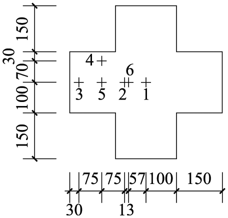
Locations of thermocouples at the mid-height of the columns.
Test apparatus
Fire test furnace
Figure 5(a) shows the fire test apparatus, which was a multi-functional fire test furnace at the Jiangsu Key Laboratory of Structural Engineering in Suzhou University of Science and Technology. The furnace is composed of a heating chamber and an automatic fire control system, of which the interior faces’ area is 3000 mm × 2000 mm and the height is 3300 mm. The temperature inside was measured by five thermocouples distributed uniformly in the furnace room.
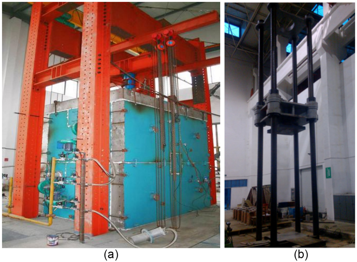
General view of the test apparatus: (a) fire furnace and (b) compression test machine.
The apparatus also included a high-temperature camera device, displacement acquisition equipment, and an automatic data collection system. During the fire testing process, displacement sensors were installed symmetrically at the top end of the specimens to record the axial deformation of specimens. The axial loading capacity of the furnace is 5000 kN.
Compression test machine
The axial compression tests of three post-fire test series specimens and the control specimen were conducted at the Key Laboratory of Concrete and Prestressed Concrete Structure of the Ministry of Education, Southeast University. A four-column compression test machine whose maximum vertical loading capacity is 10,000 kN was used in the axial compression tests.
Test procedures
The specimens of fire test were first installed in the furnace, and then a hydraulic jack was used to apply a concentric load to the specimens under fire. For all five fire test specimens, the hinged–hinged end conditions were simulated using a specially designed pin rocker bearing system, as shown in Figure 6(a).
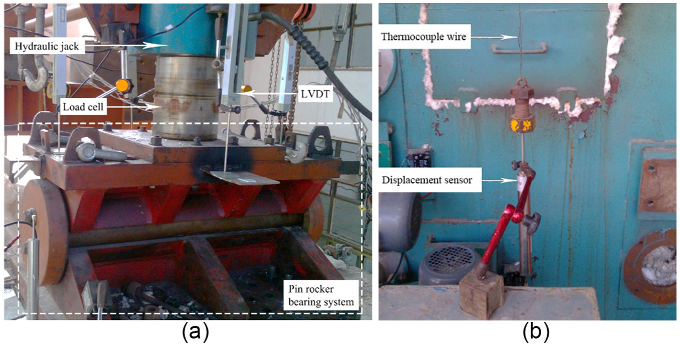
Deformation measurement: (a) measurement of axial deformation and (b) measurement of lateral deformation.
In the fire resistance tests, after the two specimens were loaded into the designed axial load under fire, as listed in Table 1, and the load was maintained for 30 min until no further increment in axial deformation and horizontal deflection occurred, the fire was started under the constant load. During the tests, the heating regime was computer-controlled to ensure that the average temperature of the thermocouples at different positions of the furnace followed the ISO-834 standard temperature–time curve as closely as possible. The cracking and the spalling of the concrete were monitored and recorded by the high-temperature television system. The axial deformations of the specimens were measured during the whole test process by LVDTs (linear variable displacement transducer) installed outside the furnace. Because the displacement sensors cannot touch the specimens directly, two thermocouple wires were used to connect the opposite surfaces of two limbs at mid-height of specimens with the displacement sensors out of the furnace. The measurement of the deformation is shown in Figure 6.
According to the specifications in Fire-Resistance Tests-Elements of Building Construction (GB/T 9978.1-2008), when the vertical load applied by the hydraulic jack could not be maintained and decreased quickly, the rate of axial deformation reached 9 mm/min, or the total deformation reached 30 mm, the specimens were considered to have failed, and the test was terminated. Thus, the duration from starting fire to this failure point is viewed as the fire resistance of the specimens. Here, both the rate of 9 mm/min and the limitation of 30 mm were calculated from the effective length of the specimens exposed to fire of 3000 mm in this experimental program.
The post-fire performance tests included two stages: the under-fire test stage and the axial compression test stage. The processes of the under-fire test stage were very similar to those of the fire resistance test of FR-100 and FR-200. During this under-fire stage, the specimens were also first axially loaded to a constant value load and then burned to a specific time instead of being burned up to failure. After being cooled down and removed from the furnace, the specimens were axially compressed to failure on the compression test machine; the maximum load achieved for each specimen during this axial compression test stage was taken as the post-fire residual bearing capacity. The axial compression tests of the controlled specimen NF-000 and the post-fire tests specimens were the same.
Experimental results
Axial compression test of specimen NF-000
The controlled specimen NF-000 was directly axially compressed to fail on the test machine under ambient temperature, and all the operations strictly followed the Chinese Specification for Test Method of Concrete Structures (GB/T50512-2012). Very small deformation and no cracks could be observed before the load reached 70% Pu, where Pu is the ultimate load of the specimen tested. When the load reached 70% Pu, some vertical tiny cracks appeared on the concrete surface of the specimen, and during the period the load increased from 80% to 90% Pu, cracks propagated quickly. Finally, when the load reached Pu, the concrete was seriously crushed at the area close to the top end or load end of the specimen, and the longitudinal bars buckled and exposed, as illustrated in Figure 7. The tested ultimate load Pu was 6650 kN, as listed in Table 1.

Failure modes of specimens.
Fire resistance tests
For specimen FR-100, during the fire resistance test, the color of the column surfaces became darker and quickly became slight red in approximately 10 min, with a large amount of water vapor observed rising from the top of the furnace; the color of the concrete turned to dark red in the next 30 min. At 40 min, the color of the concrete surface turned to slight red and the surface remained in that color until the test was completed. Once the axial deformation of the specimens increased suddenly, the test was terminated. As shown in Figure 7, after the furnace cooled down and was opened, it was found that the specimen was bent slightly, and the concrete at the corner of each limbs was spalled severely because of the accumulation of hot gas around the upper part of the furnace chamber; the damage was more serious at the area close to the top end of the specimen, resulting in the buckling of the longitudinal reinforcements exposed at that area. Many longitudinal cracks were observed on the concrete surface without spallation, and the width of some large cracks exceeded 1 mm.
Compared with specimen FR-100, the failure of specimen FR-200 was more serious. After the test, large lateral deformation was found on specimen FR-200, and the spalling area, where many large blocks of concrete dropped off and the reinforcement bars were exposed, which was much larger than that of specimen FR-100, as illustrated in Figure 7. The cracks on the surface of the unspalled concrete were observed to reach 3 mm in width.
Figure 8(a) shows that the axial deformations of two specimens were very small during the first heating hour; subsequently, the axial deformation increased at a steady rate for almost 2 h. The axial deformations increased abruptly and developed very quickly near the failure point, indicating the fire failure of specimens and providing the heating time of fire resistance. Figure 8(b) shows the lateral deflection of the two specimens. The lateral deformation attributed to the fire-induced decrease in lateral rigidity and the additional moment applied on the cross section at the mid-height of specimens developed slower than the axial deformation in the later stage of the test. Hence, it could be concluded that the sudden increase in the lateral deflection at the end of the tests was caused by the axial compression. The fire-induced decreases in the elastic modulus and the strength of the material eventually led to the reductions in axial compression capacity and stiffness of the specimens; these reductions caused large axial deformation and lateral deformation, which in turn caused additional moments and accelerated the failure of the specimens.
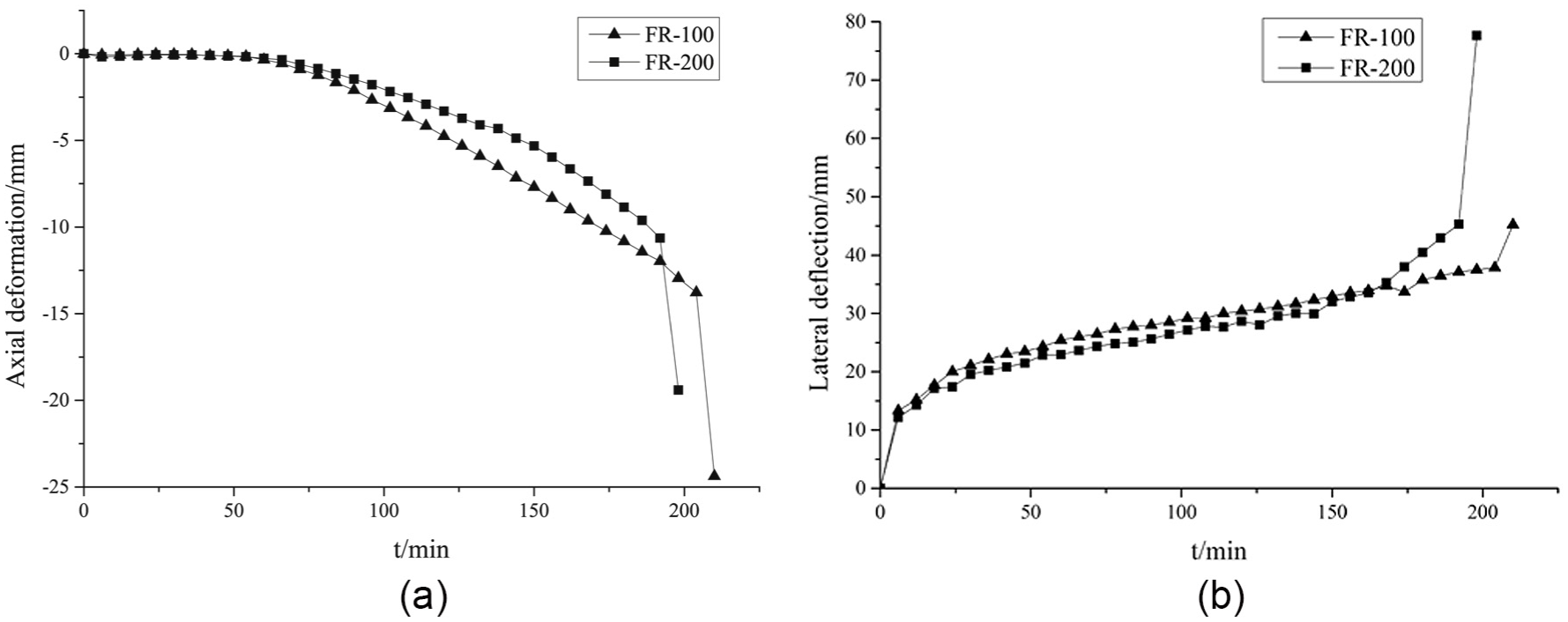
Measured deformation versus time curves of fire resistance test series specimens: (a) axial deformation versus time curves and (b) lateral deflection versus time curves.
Axial compression tests on specimens after fire
Figure 9 shows a representative view of the columns following the fire test, neither explosive spalling on the column surface nor column bucking was observed in any of the specimens. During the fire test, for specimens PF-060, PF-090, and PF-120, the phenomena were the same as those of specimen FR-100 at the 1-, 1.5-, and 2-h points, respectively. The maximum width of the cracks observed after the fire test of specimen PF-120 was over 2 mm, that of specimen PF-090 was slightly less than 2 mm, and that of specimen PF-060 was 1 mm.
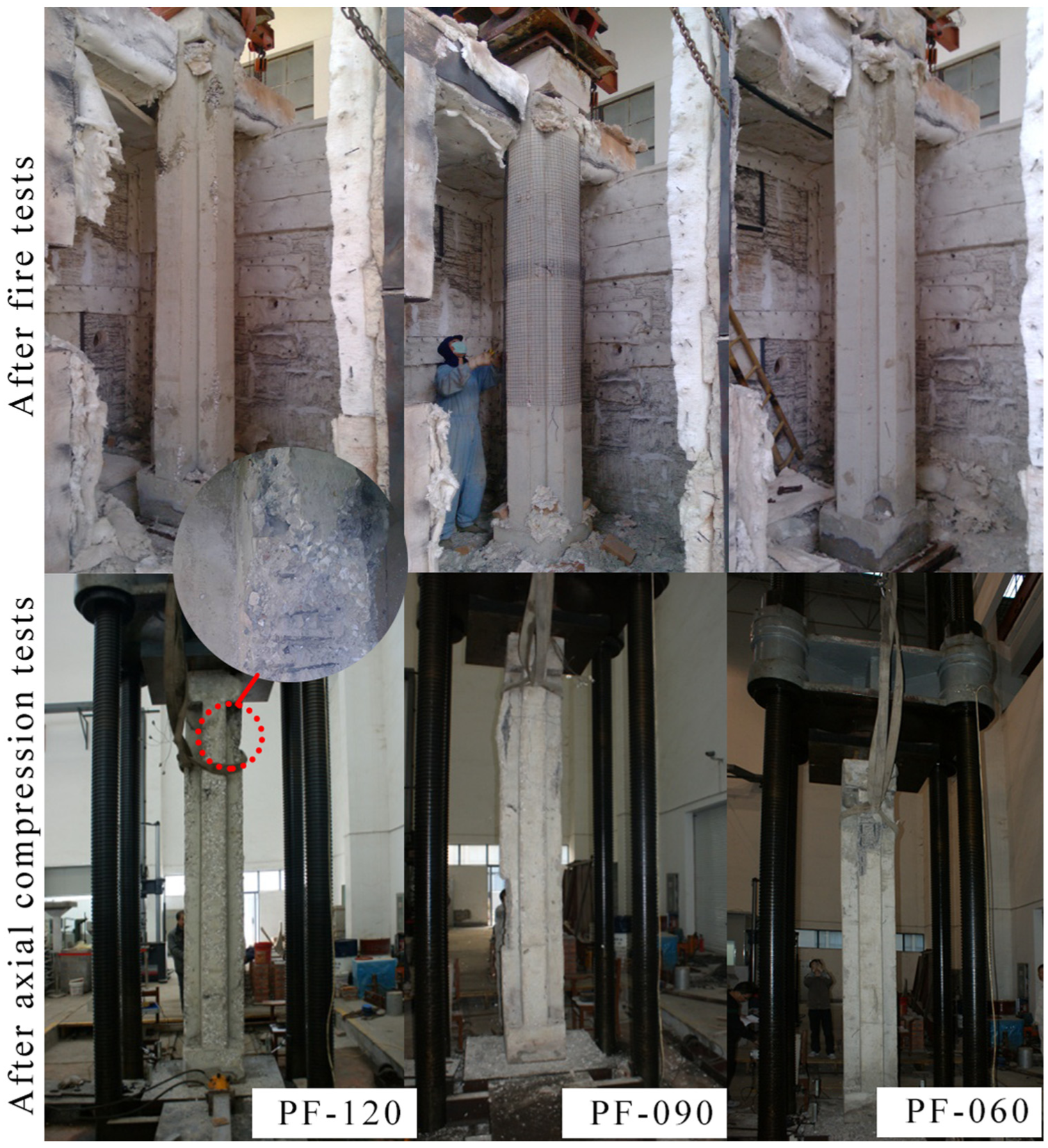
Failure pattern of post-fire test specimens.
Figure 10 reveals that the axial deformations of the three specimens were very small, with the maximum axial deformation of 3.25 mm during the heating period. Comparatively speaking, the lateral deflections of the three specimens were smaller than that of specimens of fire resistance series test, with the maximum lateral deflection of specimen PF-120 exceeding 32 mm. It can be found that the lateral deflection could gain full development after the specimens have been exposed to fire for more than 120 min, and the function of additional moment caused by upper load and fire-induced damage to the cross section of specimens appears more obvious at that period.
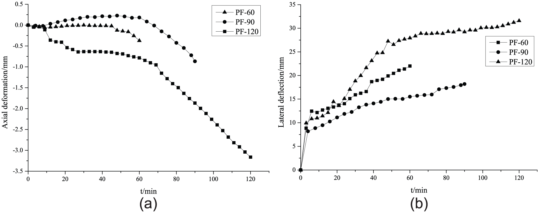
Measured deformation versus time curves during fore test of post-fire test series specimens: (a) axial deformation versus time curves and (b) lateral deflection versus time curves.
Three post-fire test specimens were moved to the axial compression test machine and then were axially compressed to fail after cooling down, from which the residual capacities of the specimens after fire were obtained. The test procedure and process were the same as those for the axial compression test of control specimen NF-000; even the failure process and failure pattern were the same as that of specimen NF-000. The failure patterns of the three specimens are shown in Figure 9.
Discussion
Cross-section temperature
The variation of temperature in the internal cross section of the specimens was measured in real time by the six thermocouples placed at the mid-height of the column under test; the results are plotted in Figures 11 and 12.
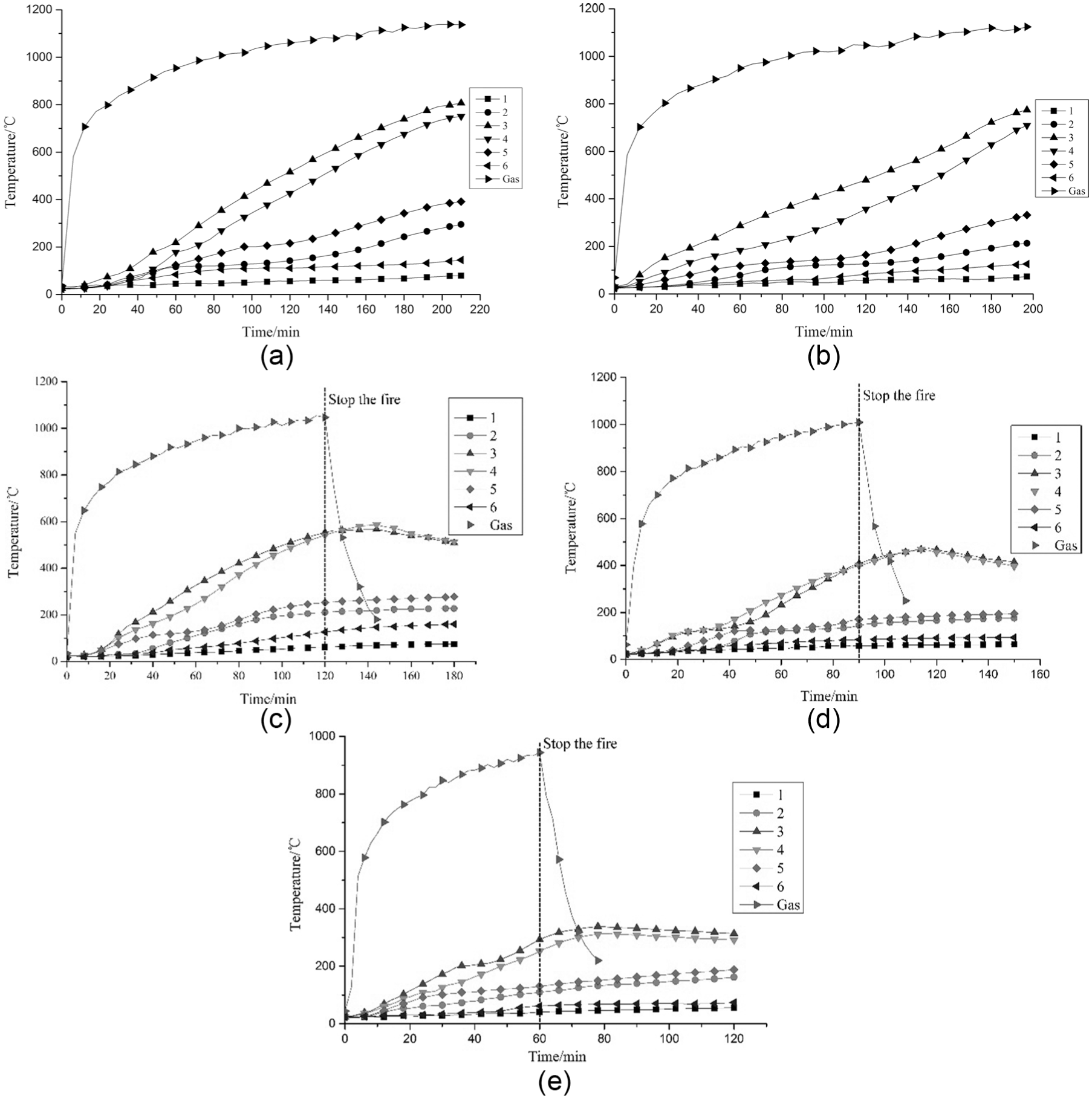
Measured temperature–time curves of thermocouples and temperature distribution of specimens: (a) specimen FR-100, (b) specimen FR-200, (c) specimen PF-120, (d) specimen PF-090, and (e) specimen PF-060.
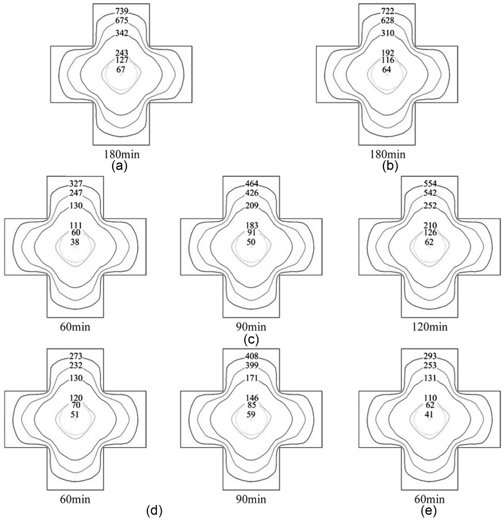
Measured temperature distribution of specimens: (a) specimen FR-100, (b) specimen FR-200, (c) specimen PF-120, (d) specimen PF-090, and (e) specimen PF-060.
The trends in Figure 11 show that the rate of temperature rise in concrete slows down at approximately 100°C, indicating a temperature plateau, which is more obvious at the points far away from the column surface; this plateau is mainly attributed to the consumption of a significant amount of energy via the evaporation of water in concrete. Compared with FR-100, the growth rates of temperature at points 3 and 4 in FR-200 have the trend of being accelerated in the later stages of the test. This phenomenon can be attributed to the occurrence of fire-induced spalling or cracking in concrete, followed by the penetration of heat flux via the damaged concrete, resulting in the accelerated rise rate of the temperature in the internal concrete and steel profile (Kodur et al., 2003).
Figure 12 shows that the temperature at the inner layers of concrete rises slowly compared to the outer layers, and these measured temperatures decrease with increase in depth from the surface. This result is caused by the low thermal conductivity and high thermal capacity of concrete, which slows down the heat penetration to the inner layer of concrete. A review of the measured temperatures plotted in Figure 12 indicates that the whole cross section has not been fully cooled down at 60 min after termination of heating. with only the measurement points 3 and 4 close to the outer concrete in the cooling phase, whereas points 1, 2, 5, and 6 were being heated at a low rate; this heating can be attributed to the thermal hysteresis or insulation effect of concrete.
Considering the geometric similarity and symmetrical reinforcement, as well as the same fire condition, it can be assumed that the four-column limbs of the tested columns have the same temperature distribution and gradient. With that assumption, the isotherm on the sectional temperature field at different times can be described in Figure 12 based on the tested results of the temperature at each point.
Because of the insulation effect of concrete, the temperature in the core remains low throughout the fire duration (the maximum temperature of the core concrete of just 67°C occurred at point 1 of specimen FR-100, whereas the maximum temperature of the steel cylinder surface of 127°C occurred at point 6 of specimen FR-100), which effectively avoids the explosive spalling of high-strength concrete. As a result, the insulation effect of concrete plays a significant role in exploiting the advantages of high-strength concrete (Chiang and Tsai, 2003).
From a comparison of the temperature distributions of the five specimens, no substantial difference was observed in the temperature distribution regularity, highlighting the good consistency of this experimental program.
Fire resistance
The deformation process of the fire resistance test specimens can be divided into three stages: stable stage, gradually increase stage, and abrupt failure stage. Under the combined effect of axial load and high temperature, spalling of the concrete in the column occurred, and loss of the crisscross section accelerated the rise in temperature in the reinforcing steel and the inner concrete, thereby hastening the failure of the columns.
The maximum axial deformations of specimens FR-100 and FR-200 were 14.99 and 11.70 mm, respectively, demonstrating that the time of exposure to fire has a significant influence on the axial deformation. The fire resistances of specimens FR-100 and FR-200 with the high axial compression ratio of 0.48 were 210 and 197 min, respectively, which can fully meet the level-1 fire resistance requirement of the specifications in the Code for Fire Protection Design of Tall Buildings (GB50016-2014) in 3 h.
Existing research results (Wu and Hong, 2005) show that the axial compression ratio plays a significant role in the fire resistance of the crisscross-shaped composite column. The experiments at columns with similar section types, size, and reinforcement, but without the CFST core, were conducted by Xu (2006). In those experiments, the fire resistance of the crisscross-shaped RC column without CFST core was 165 min under 0.45 axial compression ratio, and the fire resistance of the specimen FR-200 was 197 min under 0.48 axial compression ratio, representing an increase of more than 19.4% in fire resistance. This result demonstrates that the inner high-strength CFST core has a significant influence on the fire resistance of the columns.
The spacing of the stirrups in specimen FR-100 was only half of that of specimen FR-200, and the measured fire resistance of FR-100 was found to be higher compared with that of the specimen FR-200, in agreement with the qualitative studies performed in the reference of Kodur et al. (2003). However, the fire resistance of specimen FR-100 only improved approximately 6.5% compared with that of specimen FR-200, showing that the spacing of the stirrups had little effect on the fire resistance in this type of column with CFST core.
Residual axial bearing capacity of specimensafter fire
Figure 13 shows the load–deformation curves obtained from axial load performance test on specimens PF-120, PF-090, and PF-060 after exposure to fire and on specimen NF-000 without exposure to fire. The axial compression capacities of each specimen are listed in Table 1. Several conclusions can be drawn from the test results:
The tangent of the load–deformation curve remains relatively constant, that is, the stiffness of this type of specially shaped composite column was stable during the test and no significant reduction in stiffness occurred.
The ultimate capacity of this specially shaped composite column with high-strength CFST core is 6650 kN under ambient temperature, representing an improvement of approximately 5.6% compared with the result of the theoretical calculation that did not consider the effect of slenderness ratio of 6300 kN. However, normal cross-shaped RC columns with the same cross section and material only have a capacity of 5496 kN (Xu et al., 2007). It can be concluded that the measured bearing capacity provided by the CFST cores in combination with the cross-shaped columns is approximately 1150 kN. This value is close to the theoretical axial compressive bearing capacity of the high-strength CFST cores, showing that the cores have played their parts completely. This result was obtained because the core bears the axial load directly and the outer concrete prevents the steel tube from undergoing general bucking and local bucking, enabling the advantages of the steel tube and the high-strength concrete to be fully exploited, and resulting in the improvement of the overall axial capacity of specimens.
Because of the effect of the inner CFST core, cracking in the concrete of the column develops more slowly under ambient temperature. Xu et al. (2007) found that the cracking load of normal cross-shaped RC column is 36% of its ultimate load. In this experimental program, the cracking load of specimen NF-000 is approximately 70% of the ultimate load, which indicates that the inner CFST core effectively delayed the occurrence of cracking and inhibited the column from entering into the cracking state prematurely.
The capacity reduction ratios of specimens PF-120, PF-090, and PF-060 were 0.761, 0.839, and 0.890, respectively, which indicates that the residual axial bearing capacity of post-fire test specimens decreased with an increase in the fire exposure time.
The slope of the load–deformation curve of the specimens decreased with increasing fire exposure time, that is, the reduction in stiffness of columns occurred with increasing fire exposure time. With the degradation of the stiffness, the axial stiffness reduces, resulting in larger compressive deformations.
The inner CFST core provided significant improvement in the residual axial bearing capacity of post-fire test specimens. According to the experiments conducted by Wu and Li (2010), with exposure to fire for 90 and 110 min, the capacity reduction ratios of the cross-shaped column without this core were 0.45 and 0.51 respectively, and those of the columns with CFST core were 0.761 and 0.839 after 90 and 120 min, respectively, of exposure to fire. The protection provided from the outer concrete effectively avoids the fire-induced spalling of the high-strength concrete in the core tube, indicating that the contribution of the high-strength CFST core to the axial bearing capacity of specimens mostly survives the fire test and accounts for a large proportion of the residual axial bearing capacity.
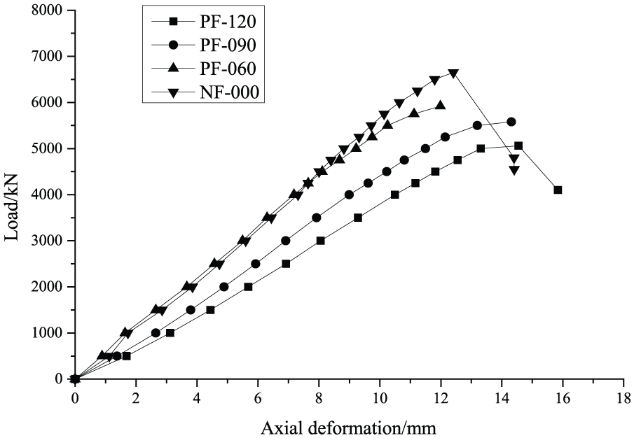
Curves of axial load versus deformation.
From the analysis above, overall, it can be concluded that a specially shaped composite column with high-strength CFST core exhibits good post-fire and mechanical performance.
Conclusion
The following conclusions can be drawn:
Specially shaped composite column with high-strength CFST core exhibits higher ultimate bearing capacity under ambient temperature compared to normal RC specially shaped columns; the CFST core can be brought into full play in the axial bearing capacity and delay the occurrence of cracking in the concrete effectively.
The failure modes of the specially shaped column with CFST core in the post-fire test series under axial compression were similar to those of a similar column at ambient temperature.
The spacing of the stirrups did not affect the fire resistance or the post-fire performance of the specially shaped column with CFST core under axial compression.
The inner CFST core played an important role in both the fire resistance and the post-fire performance, with the fire resistances of specially shaped composite columns being more than 3 h, even under a high axial compression ratio of 0.48.
The residual bearing capacity and residual stiffness of the specially shaped column with CFST core decreased with increasing fire exposure time. After exposure to fire for 60, 90, and 120 min, the capacity reduction ratios were 0.890, 0.839, and 0.761, respectively.
Because of the contribution of the inner CFST core, the specially shaped column with the CFST core has greater capacity ratio and exhibits better fire performance compared with the normal specially shaped columns without this core. The inner CFST core played a significant role in the residual bearing capacity and mechanical behavior in post-fire test series.
Footnotes
Declaration of Conflicting Interests
The author(s) declared no potential conflicts of interest with respect to the research, authorship, and/or publication of this article.
Funding
The author(s) disclosed receipt of the following financial support for the research, authorship, and/or publication of this article: Natural Science Foundation of China(Grant No:51578443);State Key Laboratory of Subtropical Building Science Autonomous Research Subject(X2JZ-C710071Z).