
Abstract
Many existing deep reinforced concrete coupling beams that have low span-to-depth ratios are not desirable for seismic design due to their potential brittle failure with limited ductility and deformability. Previous experimental and numerical studies have demonstrated that the laterally restrained steel plate retrofitting method could effectively enhance the seismic performance of deep coupling beams. This article aims to develop a nonlinear finite element model based on the OpenSees software to accurately predict the behavior of coupled shear walls with or without laterally restrained steel plate coupling beams. The numerical results reveal that the seismic performance of the laterally restrained steel plate retrofitted coupled shear walls can be significantly enhanced. Furthermore, a genetic algorithm is adopted to determine the optimal positions of laterally restrained steel plate coupling beams. It is found that desirable seismic performance can be achieved by retrofitting coupling beams in the middle and higher floors of a building with coupled shear walls. However, only retrofitting coupling beams on the lower floors should be avoided because this could result in the serious degradation of the lateral load-carrying capacity and stiffness of the coupled shear walls.
Keywords
Introduction
Reinforced concrete (RC) coupled shear walls are typically used in lateral load resisting systems in the design of high-rise buildings. Coupling beams, which connect individual wall piers, are a critical component that provides lateral strength, stiffness, and deformation capacity to an entire building. In the past decades, the design of many concrete buildings in moderate seismicity regions, like the South China region including Hong Kong, did not take earthquake actions into account. Following the new seismic design codes, many existing coupling beams, especially those with a low span-to-depth ratio (less than 1.5), are presumed to have inadequate earthquake resistance which could fail in brittle shear modes and are not acceptable in seismic assessments of coupled shear wall systems (Kwan and Zhao, 2002; Paulay, 1971). The local failure of coupling beams could lead to global failure of coupled shear walls (Smith et al., 1991). To improve the seismic resistance of existing buildings, coupling beams that are deficient in shear or lack deformability will need to be retrofitted.
Harries et al. (1996) investigated the different ways to fix a thin steel plate to one side of coupling beams with a span-to-depth ratio of 3. Their study revealed that a hybrid method of bolting and epoxy bonding to attach steel plates both in the span of the beams and at the ends is more desirable. Su and Zhu (2005) conducted experimental and numerical studies on coupling beams with a span-to-depth ratio of 2.5 reinforced with bolted steel plates without adhesive bonding. In their study, minor buckling of the steel plates was observed but the effects of local buckling on the behavior of the composite coupling beams were not investigated.
Cheng and Su (2011) proposed the use of bolted steel plate with lateral restraints (without stiffeners) to retrofit deep RC coupling beams with a span-to-depth ratio of 1.1. Steel angles were used to suppress plate buckling mode and enhance stable shear yielding mechanism of steel plate. Their test results revealed that this method, namely laterally restrained steel plate (LRSP) method, could substantially enhance the post-peak behavior, deformability, and energy dissipation ability of deep RC coupling beams. However, the shear buckling of the steel plates in the early stages usually results in reduced strength, stiffness, and energy dissipation capacity and shows significant pinching. To mitigate these problems, Cheng et al. (2016) added stiffeners to LRSP to further suppress the premature plate buckling and expand the yield zone for better energy dissipation. Cheng et al. (2017) used nonlinear finite element analysis to investigate the effect of stiffener arrangements on the performance of the LRSP retrofitted coupling beams. Their numerical studies showed that when the stiffeners diagonally pass through the center of the steel plate, there is better control of the concrete cracks and a more ductile failure mode is achieved.
However, analyses on the seismic response of coupled shear wall systems with retrofitted coupling beams have been rarely reported. Meftah et al. (2013) investigated the seismic behavior of RC coupled shear walls with coupling beams reinforced through bonding with thin composite plates. A finite element model was established for both three layered sandwich coupling beam and wall elements. Their study revealed that the use of carbon fiber–reinforced polymer (CFRP) composite plates to reinforce coupling beams reduces the lateral deflection of the structure. The effectiveness of the proposed reinforcing method depends on the geometrical characteristics of the shear wall structures and the dominant range of frequencies of the input earthquake records. Chaallal and Nollet (1997) proposed the use of a few deep coupling beams with optimal number and locations to improve the coupling ratio (
Currently, the seismic behavior of RC coupled shear wall systems with LRSP retrofitted coupling beams and the optimal retrofitting arrangement have yet to be investigated. Therefore, in this article, a nonlinear finite element model based on the Open System for Earthquake Engineering Simulation (OpenSees) software (McKenna, 2011) is developed to simulate the behavior of coupled shear walls with or without LRSP coupling beams. Then the effect of LRSP retrofitting method on the behavior of the coupled shear wall systems is investigated. Finally, recommendations for optimal retrofitting arrangements obtained from a genetic algorithm (GA) are provided.
LRSP retrofitting method
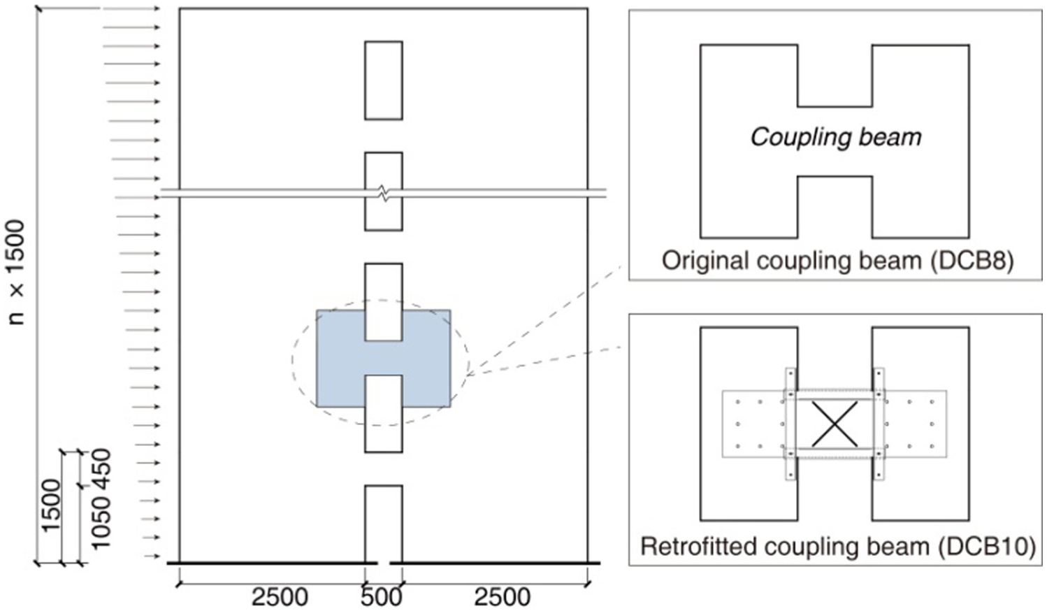
The main characteristic of LRSP retrofitting method is the use of a device that controls plate buckling, which is composed of steel angles (Figure 1(a)). To avoid adding extra strength and stiffness to the retrofitted coupling beam, the lateral steel angles are connected to a steel plate through bolt connections in slotted holes, which allow two lateral stiffeners to freely rotate and move in the longitudinal direction. The advantage to using a device that prevents plate buckling as opposed to adding stiffeners to the steel plates is that the coupling beams would not increase in flexural stiffness. This is important because an increase in flexural stiffness would stiffen the lateral load resisting system and cause the structure to attract more seismic loads, which might lead to brittle compressive or shear failure of the coupled shear walls under strong seismic loads. Moreover, previous experimental and numerical studies by Su and Cheng (2011) and Cheng et al. (2016) have demonstrated that diagonal stiffeners used on LRSP to retrofit coupling beams such as the DCB10 specimen (as shown in Figure 1(b)) provide better deformability and energy dissipation ability. To validate the effectiveness of the retrofitting method on the seismic resistant performance of the entire structure, nonlinear finite element analysis is conducted. In the following numerical studies, a macro model for retrofitting coupling beams is built based on the test results with DCB10.
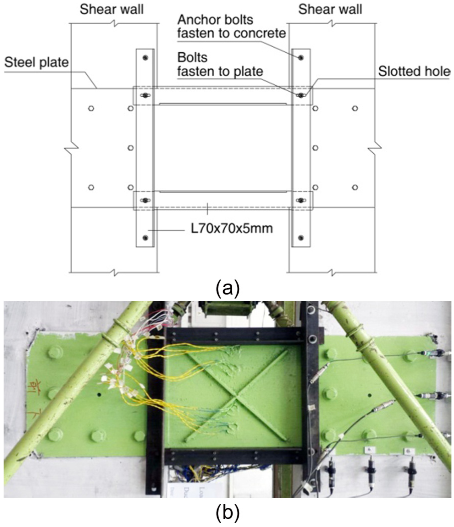
LRSP retrofitting method: (a) plate buckling control device and (b) diagonal stiffeners used on steel plates to retrofit coupling beams (DCB10).
Numerical modeling
A nonlinear finite element model was created to simulate coupled shear walls with OpenSees. The coupling beams were simulated using the concentrated shear hinge model (Wallace, 2012) and the RC shear walls were simulated using fiber beam elements (Taucer et al., 1991). To obtain more accurate results, the nonlinearity of the materials was properly simulated in the finite element model.
Macro model of coupling beams
In this study, both the RC coupling beams and LRSP retrofitted coupling beams are simulated using the concentrated shear hinge model (Vn-hinge model). In this Vn-hinge model, a nonlinear shear-displacement spring at beam mid-span is utilized to account for both shear and flexural deformations. To implement the Vn-hinge model in OpenSees, a two-node link element (Figure 2), which consists of linear or nonlinear axial, shear and flexural springs, is adopted.
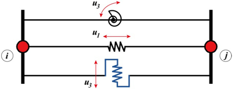
Two-node link element.
The axial-displacement spring was defined with a constant stiffness EA/l, where E is the elastic modulus of the RC, A is the section area of the coupling beam, and l is the length of the coupling beam.
A hysteresis model was defined for the shear-displacement spring, which contains three parts: the backbone curves of the hysteresis loops, hysteresis criteria (characteristics of the hysteretic behavior), and degradation criteria (Applied Technology Council (ATC), 2010). The trilinear backbone curve in one loading direction can be obtained using three key points (yield, peak, and residual points) as shown in Figure 3, which can all be obtained based on the test results (Cheng et al., 2016). The yield points were determined using the equivalent energy method and the residual strength point was set as 20% of the peak strength.
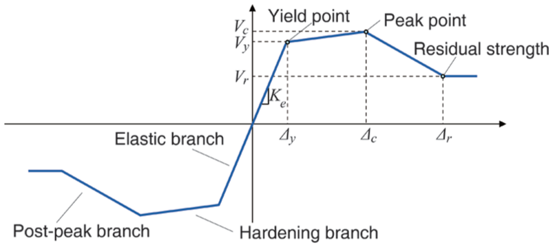
Trilinear backbone curve.
This macro model of the coupling beams was then validated with the experimental results (Cheng and Su, 2016). Figure 4 shows a comparison between the experimental and analytical results for DCB8 (an RC coupling beam) and DCB10 (LRSP coupling beam). It can be observed that the proposed macro Vn-hinge model developed using OpenSees accurately simulates the cyclic behavior of deep coupling beams.
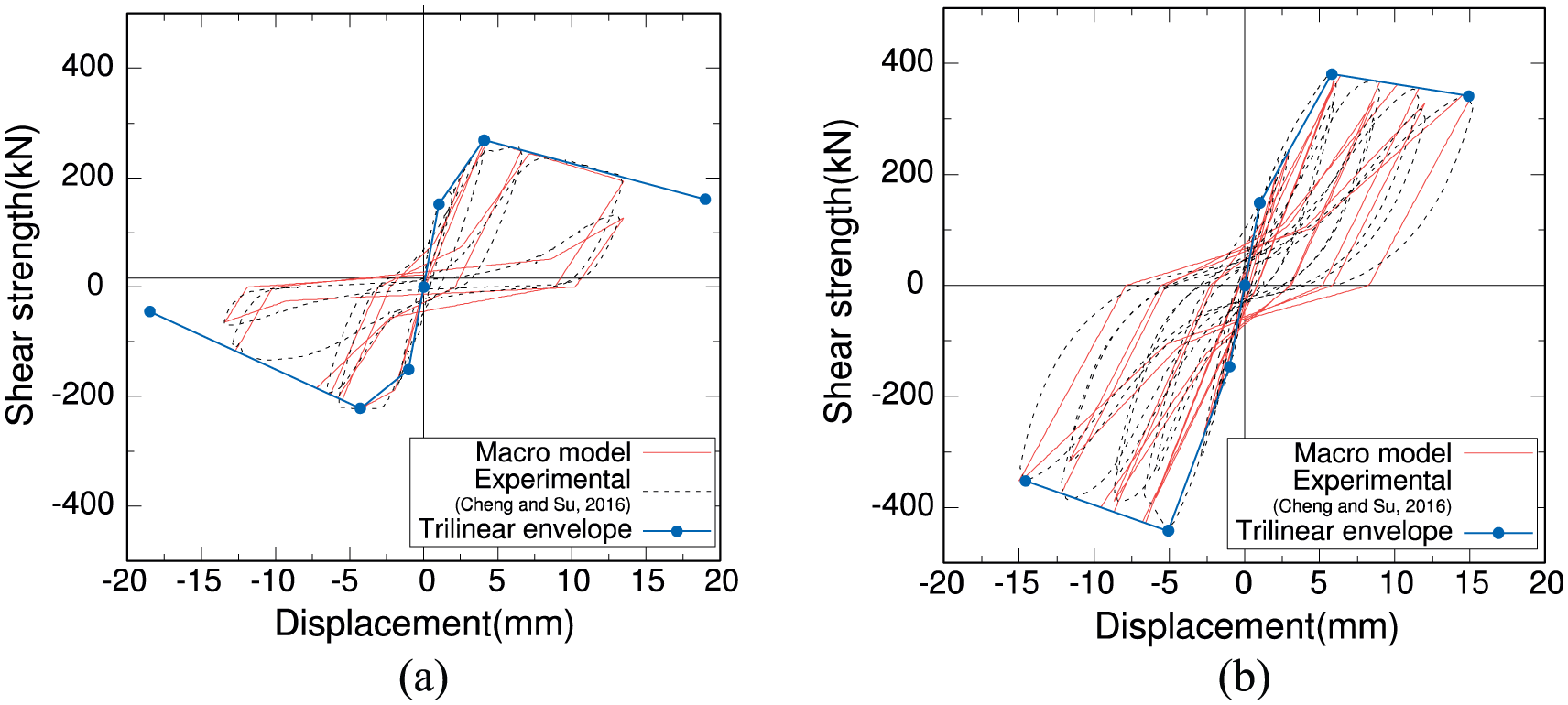
Experimental and numerical load displacement curves: (a) DCB8 and (b) DCB10.
Refined model of shear walls
The shear walls were modeled using a fiber beam–column model with distributed plasticity due to its good accuracy, numerical stability, and efficiency (Lu et al., 2015; Taucer et al., 1991). To implement this model on the OpenSees platform, a displacement-based beam–column element with an assigned fiber cross section was selected to simulate the RC shear wall.
The fiber section of RC wall was divided into four parts: unconfined concrete cover, unconfined concrete in wall web, confined concrete in the boundary element, and reinforcing steel. Using the material model Concrete01 in OpenSees, the constitutive model of concrete fibers was assumed to follow the Kent–Park stress–strain model of concrete (Kent and Park, 1971) and the corresponding hysteretic rules which considered nonlinear elasticity behavior and softening in compression. The confinement model proposed by Mander et al. (1988) was adopted to calculate the characteristic parameters of the unconfined and confined concrete. Using the material model Steel02 in OpenSees, the reinforcing steel fibers were modeled as an elastic–plastic isotropic material with a similar response in compression and tension (Filippou et al., 1983).
The fiber section of the RC shear wall was divided into four parts: unconfined concrete cover, unconfined concrete in wall web, confined concrete in the boundary element, and reinforcing steel. A uniaxial material, Concrete01 (Kent and Park, 1971), was used to simulate concrete fibers and a uniaxial material, Steel02 (Filippou et al., 1983), was used to simulate the reinforcing steel fibers.
Combined model of coupled shear walls
The model for simulating coupled shear walls is composed of a macro element of coupling beams and a fiber beam–column element of shear walls, as shown in Figure 5. In the combined model, rigid beams are introduced between the nodes of the shear wall beam–column elements and the corresponding nodes of the coupling beam element to represent the physical size of the wall. Hence, the degrees of freedom between the wall piers and the coupling beams can be precisely coupled.
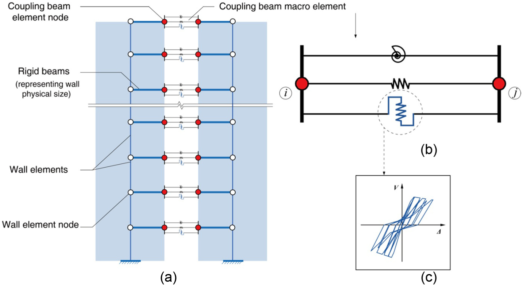
Combined model for coupled shear wall: (a) coupled shear wall model, (b) two-node link element, and (b) hysteresis model of coupling beam.
Verification of the combined models
The refined model of shear wall and combined model of coupled shear wall have been validated with the experimental results. Figure 6 shows the comparison of the experimental and analytical results of S5 (conventional RC shear wall specimen) and S1 (slotted shear wall specimen) (Deng et al., 2017). As shown in Figure 6(b), the slotted shear wall S1 consists of three parallel shear walls connected by six steel shear links. The shear links are modeled with the macro model of coupling beam and its hysteresis model is determined from the test results of shear links (Deng et al., 2017). It can be found that the proposed refined model of shear wall and the combined model of coupled shear wall developed from OpenSees can accurately simulate the load–deflection curves of both specimens.
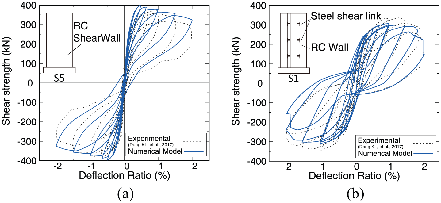
Verification of the numerical models (a) refined model of shear wall and (b) combined model of coupled shear walls.
Seismic analysis of coupled shear wall with LRSP retrofitted coupling beams
To investigate the seismic performance of coupled shear walls with and without LRSP retrofitted coupling beams, a nonlinear static analysis (pushover analysis) is conducted based on the combined model for coupled shear walls. Some of the coupled shear walls in buildings with a different number of stories (from 12 to 16 stories) were numerically studied. Figure 7 shows the layout and dimensions of two retrofitted coupled shear walls. RCSW and CSW denote retrofitted coupled shear walls and coupled shear walls, respectively. In these models, the concrete compressive strength is taken as 38.5 MPa and steel reinforcement ratio of 2.0% is adopted.
Geometric characteristics of original coupled shear wall.
The inter-story drift ratio (IDR) has been widely used in earthquake engineering design and various design codes as an important index to evaluate the damage of structures (Lu et al., 2016; Su et al., 2016). Hence, controlling the IDR is important to ensure a better performance of the coupled walls. The IDR is the difference in the displacement response between two adjacent floors divided by the height of the story. According to the Chinese Code for Seismic Design of Buildings (GB 50011-2010) (China Ministry of Construction (CMC), 2016), the maximum IDR of coupled shear walls should not exceed 1%. To compare the performances of buildings with CSW and RCSW, they are displaced to the same roof drift ratio (called target displacement), which is determined as the roof drift ratio of the CSW when the maximum IDR just reaches 1%. For coupled shear walls in buildings with 12 and 16 stories, the target displacement is 0.75% and 0.73%, respectively.
The mechanical behaviors of the coupled shear walls that are retrofitted such as the yield sequence of the coupling beams, base shear versus roof drift, degree of coupling, deformation distribution, and energy dissipation ability of the buildings with CSW and RCSW are compared and discussed.
Yielding sequences of coupling beams
Figure 8 shows the first yielding of a coupling beam at a particular story and the corresponding roof drift ratio in 12-story and 16-story buildings with CSW and RCSW, respectively. This figure also shows the yielding sequences of the coupling beams. It can be observed that the yielding sequences of the coupling beams in the buildings with CSW and RCSW are almost the same as the roof drift ratio increases. The first yielding of the coupling beams with or without retrofitting all takes place in the middle floors of the buildings and then spreads toward the higher and lower floors. After the coupling beams are retrofitted with LRSP method, the yielding sequences do not change. This is because with the use of this method, the initial stiffness of the coupling beams is only slightly increased (Su and Cheng, 2011).
Yielding sequences of coupling beams.
Base shear versus roof drift of buildings with CSW and RCSW
The pushover base shear–deflection curves of CSW and RCSW with 12 and 16 stories respectively are shown in Figure 9. Due to the better shear retention capacity and ductility of the retrofitted coupling beams, the shear capacity, stiffness, and deformation capacity of all the coupled shear walls are considerably enhanced after the coupling beams are retrofitted with LRSP.
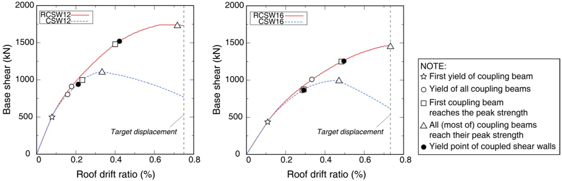
Base shear–roof drift curves of buildings with CSW and RCSW.
It can be clearly observed that in the initial phase of the pushover analysis when the roof drift ratio is less than 0.1%, the initial stiffness and shear capacity of the CSW and RCSW are almost the same because the proposed retrofitting method does not change the initial stiffness of the original coupling beams. The first yielding of the coupling beams occurs when the roof drift ratio is about 0.1% (denoted with ☆). With increasing deformation, all of the coupling beams continuously yielded when the roof drift ratio is more than 0.2% (denoted with ○), and then the stiffness of the coupled shear walls began to significantly decrease. The retrofitted coupling beams can undergo larger inelastic deformations before they reach their peak shear capacity; therefore, the first retrofitted coupling beam reaches its peak capacity (denoted with □) much later than in the CSW. It can be observed that the coupled shear walls also reach their yielding points (denoted with •) when the first failure of the coupling beams occurs. Then, with increasing deformation, all or most of the coupling beams reach their peak strength, and the shear capacity of the coupled shear walls also reaches its peak (denoted with Δ). Therefore, the behavior of the retrofitted coupling beams has a substantial effect on the performance of all the coupled shear walls.
Coupling ratio
An efficient way to improve coupled wall systems is to improve their
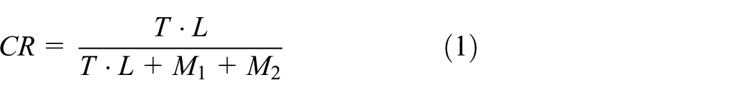
where
The 1994 CSA Standard (Canadian concrete standard) and NZS 3101 (New Zealand concrete code) stipulate that the
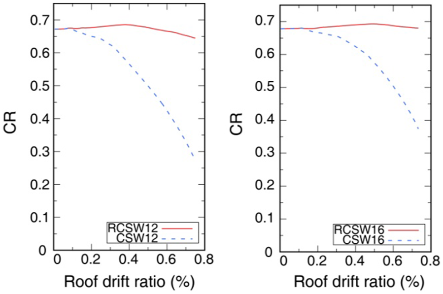
Variations in coupling ratio of buildings with RCSW and CSW with pushover analysis.
The overturning moment resisted by the wall piers and the coupling action of the beams are shown in Figure 11 for buildings with CSW and RCSW, respectively. It can be seen that for the building with RCSW, the overturning moment that is resisted by the coupling action of the beams (
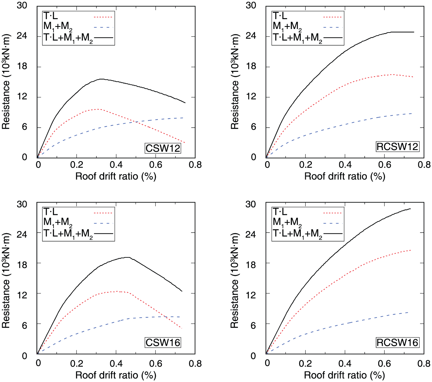
Overturning moment resisted by wall piers and coupling beams of CSW and RCSW.
Deformation curves
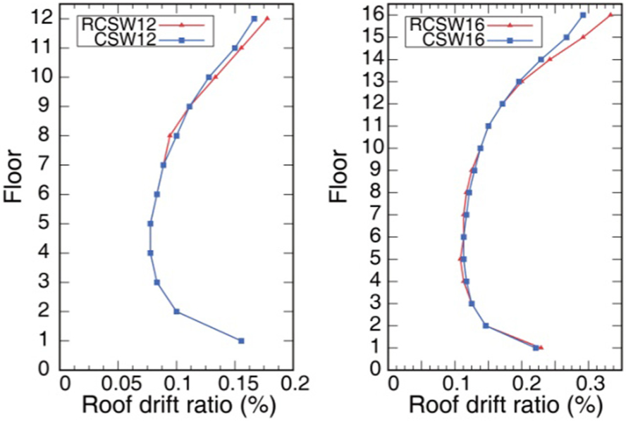
The distribution curves of the IDR for the target displacement of the buildings with CSW and RCSW are shown in Figure 12. In this study, the maximum IDR
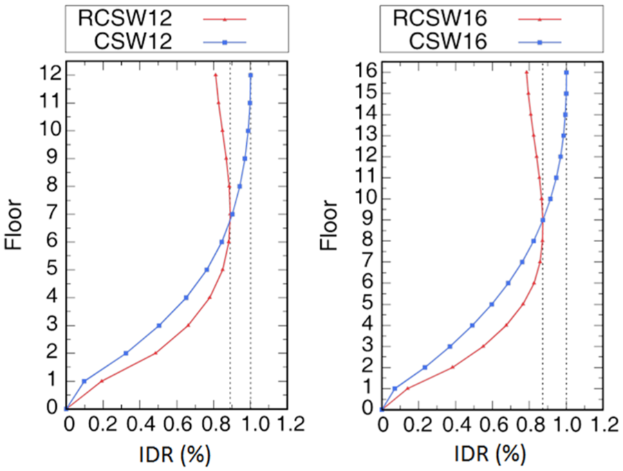
Distribution of IDR for target displacement of CSW and RCSW.
The drift concentration factor at the target displacement
Energy dissipation
To investigate the influence of LRSP method on the energy dissipation ability of coupled shear walls, cyclic pushover analysis is conducted for CSW and RCSW buildings. The energy dissipated in each cycle is evaluated. Figure 13 compared the variations of energy dissipation with the roof drift ratio for CSW and RCSW buildings with 12 and 16 stories, respectively. It can be seen that LRSP retrofitting method for coupling beams has a great effect on the energy dissipation ability of coupled shear wall buildings. The use of LRSP method to coupling beams can significantly enhance the energy dissipation ability of RCSW buildings especially in the large deformation range. In the early deformation range, both CSW and RCSW buildings are able to dissipate an increasing amount of energy as the increase of roof drift ratio. However, energy dissipation of CSW12 and CSW16 all suddenly decreases when the roof drift ratio reaching 0.4%–0.5%. This is because most of the coupling beams without LRSP retrofitted began to failure at such a roof drift ratio which leads to the decrease of lateral load capacity of coupled shear walls. While for RCSW12 and RCSW16, the dissipated energy could still increase because LRSP retrofitting method could increase the strength and deformability of coupling beams in the large deformation range.

Comparison of energy dissipation of CSW and RCSW.
Analysis for optimal retrofitting of coupled shear walls
As demonstrated in the previous sections, the proposed retrofitting method can effectively improve the seismic behavior of coupled shear walls; however, retrofitting all coupling beams of a structure could be financially costly and unnecessary, and the desirable seismic behavior could be actually realized by retrofitting fewer coupling beams but on certain floors of a building. Hence, an analysis for the optimal retrofitting of coupled shear walls is needed.
Algorithm for optimal retrofitting
For a coupled shear wall in a building with n stories, there are
The GA is implemented based on a system that integrates the Python 2.7 and OpenSees programs. Python performs the operations of GAs, generates a finite element model, controls the OpenSees program to produce the corresponding models, and collects the output data of the modeled calculations. The flowchart for the calculations is provided in Figure 14. The reduction in the
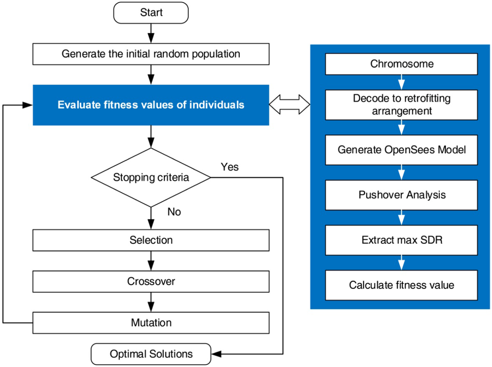
Genetic algorithm.
In this study, each retrofitting arrangement is represented with an n-bit binary number (n = the number of stories in the building with coupled shear walls). The number “1” denotes that the corresponding coupling beam is retrofitted and “0” otherwise. For example, “000000111111” denotes that the coupling beams on the 1st to 6th floors of a building are not reinforced and those on the 7th to 12th floors are reinforced.
To verify the accuracy and efficiency of the GA, an optimization problem of a coupled shear structure in a 12-story building is solved with the proposed GA and traversal method (by calculating all 4096 models), respectively. The optimal solution obtained with the GA is exactly the same as that obtained using the traversal method (by calculating all 4096 models). However, the GA greatly reduces the time required to obtain the optimal solution, from 4.5 to 0.5 h.
Optimization analysis
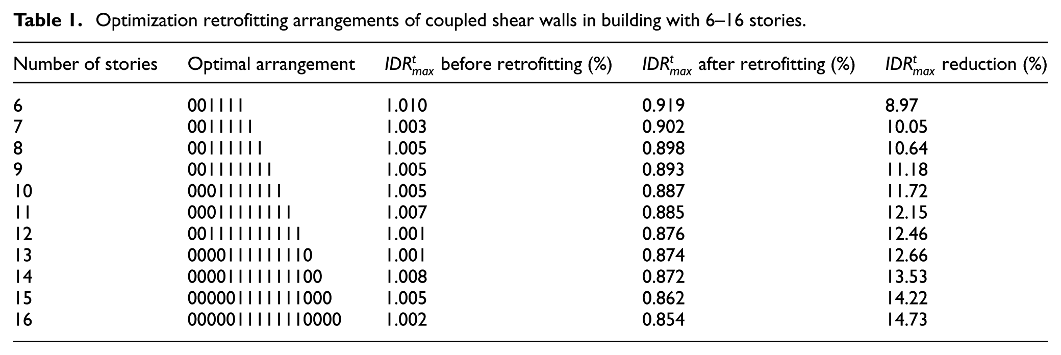
The proposed modeling techniques and the GA were utilized to investigate the optimal retrofitting arrangement for coupled shear walls in buildings with 6–16 stories. The optimization analysis of the coupled shear walls was carried out using the proposed GA and the optimal arrangements of each structure are shown in Table 1. It can be seen that the optimal arrangements are to retrofit the coupling beams on the middle and higher floors of the building. The
Optimization retrofitting arrangements of coupled shear walls in building with 6–16 stories.
Optimal retrofitting arrangements
The optimal arrangements with the use of retrofitted coupling beams for coupled shear walls in a 12-story building are presented in Table 2. It is evident that many of the mechanical properties of the building with RCSW such as the shear capacity and
Optimal arrangements with retrofitted coupling beams.
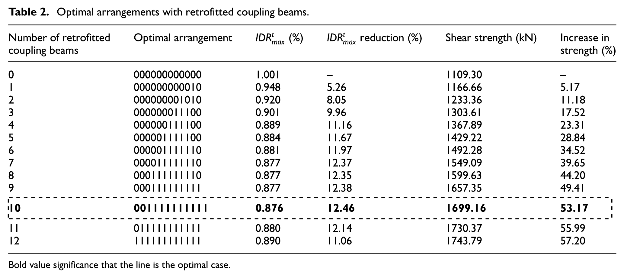
Bold value significance that the line is the optimal case.
The least ideal arrangements with the use of retrofitted coupling beams for coupled shear walls in a 12-story building are presented in Table 3. It can be found that retrofitting the coupling beams only on the lower floors (1st to 7th floors) may result in increased
Least ideal arrangements with retrofitted coupling beams.
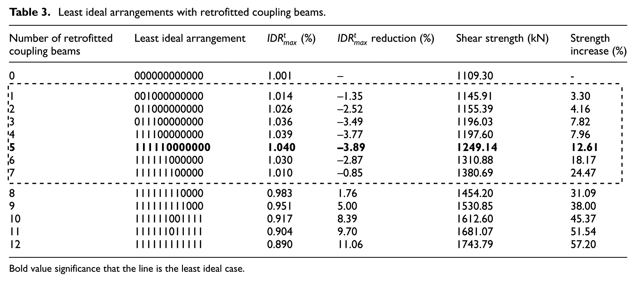
Bold value significance that the line is the least ideal case.
The end shear forces of the coupling beams and the base shear–deflection curves of the three cases (original CSW12, least ideal case 111110000000 and optimal case 001111111111) are depicted in Figures 15 and 16. Figure 15 shows the distribution of the end shear forces of the coupling beams over the entire building when the roof drift ratio reaches 0.23% and 0.4%, respectively. It can be found that for the optimal case of 001111111111 in which the coupling beams in the middle and higher floors are retrofitted (3rd to 12th floors), the shear capacity of all the retrofitted coupling beams can be maintained before reaching peak strength and no failure occurs even when the roof drift ratio reaches 0.4%. Therefore, the base shear strength and stiffness of all the coupled shear walls gradually increase until the roof drift ratio reaches 0.6%. However, when there is no retrofitting, most of the coupling beams in the middle and higher floors of the building reach their peak strength as the roof drift ratio reaches 0.23% (as shwon in Figure 15), and their failure result in the degradation of the base shear and stiffness of all the coupled shear walls as shown in Figure 16. It can also be found that although the coupling beams on the lower floors are retrofitted in the least ideal case of 111110000000, they tend to reach their peak strength earlier than those on the other floors. Failure of the coupling beams on the lower floors would also result in serious degradation of the base shear and the stiffness of all the coupled shear walls. This explains why only retrofitting the coupling beams on the lower floors may result in increases in the
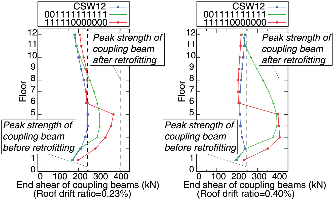
End shear forces of coupling beams.
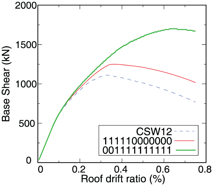
Base shear–roof drift ratio curves of selected cases.
Conclusion
A finite element analysis is conducted for an optimization analysis of the seismic retrofitting of concrete coupled shear walls using LRSP to coupling beams. The main findings of this study are summarized as follows:
This study validates the effectiveness of a combined model formulated with the Python and OpenSees programs, which consists of a macro Vn-hinge model of coupling beams and refined model of shear walls. The model can accurately predict the overall behavior of coupled shear walls that have been retrofitted.
The behaviors of the retrofitted coupling beams have a significant effect on the seismic performance of coupled shear wall systems. The strength capacity, stiffness, deformability, and CR value of coupled shear wall systems are considerably enhanced after retrofitting the coupling beams with LRSP method. Moreover, the maximum IDR at the target displacement can be reduced and the uneven distribution of the IDR can be rectified after retrofitting.
The GA which is based on Python and OpenSees is accurate and efficient in searching for the optimal retrofitting arrangement, which is to retrofit the coupling beams in the middle and higher floors of a building. The maximum IDR at the target displacement can be reduced by about 10%–15% and the shear capacity can be increased by more than 50% after LRSP retrofitting.
Only retrofitting the coupling beams on the lower floors should be avoided, as they tend to reach their peak strength earlier than those on higher floors which would result in the serious degradation of the lateral strength and stiffness of the coupled shear wall system.
Footnotes
Declaration of Conflicting Interests
The author(s) declared no potential conflicts of interest with respect to the research, authorship, and/or publication of this article.
Funding
The author(s) disclosed receipt of the following financial support for the research, authorship, and/or publication of this article: The work carried out in this article was fully supported by the National Natural Science Foundation (project no. 51208023), Beijing Natural Science Foundation (project no. 8162014), and Beijing Advanced Innovation Center for Future Urban Design (project no. UDC2016030200).