




Abstract
The hybrid coupled shear wall (HCW) with replaceable coupling beam (CB) is an optimal component to recover buildings promptly after a severe earthquake. However, the reinstallation may be difficult or impossible with an identical CB because of the inelastic relative dislocation between two wall piers. This study proposes a novel HCW with different reinforcement ratios in the connection, which was tested under cyclic loading. After the test, the bolt holes can be located through terrestrial scanning, which is then utilized to fabricate a new CB that can accommodate the deformation between two wall piers. The newly replaced HCW system was also tested. As a result, all virgin test specimens fail in web fracture and show a significant inelastic chord rotation of 0.2 rad, exhibiting an excellent energy dissipation capacity. Meanwhile, the new method to locate the bolt holes after the test is feasible. The replaced HCW fails in the pull-off of anchor bars and shows poor seismic behavior due to the unpatched concrete cover in the connection. To improve the energy dissipation for the replaced HCW, high-strength grouting in the connection can be used and high-strength material can be used to replace the usual anchor bolts.
Introduction
With the increasing development of the economy, high-rise buildings have accounted for a large proportion of urban society. Although the whole building designed according to a well-established design code would probably not collapse during a severe earthquake, some structural components such as beam-column joint, wall foot, and coupling beam (CB) may be seriously damaged and not repairable. In such cases, the buildings will have to be demolished and rebuilt, involving a high cost and long recovery from normal community activities (Parker and Steenkampo, 2012). Thus, the prompt recovery of the damaged structure after a severe earthquake is warranted to minimize the economical and societal losses. One design concept that has been proposed in recent years is the replaceable structure consisting of easily replaced components and non-damaged components. During a severe earthquake, the easily replaced components can act as fuses to dissipate the energy, keeping the remainder components elastic and undamaged (Lv and Chen, 2011). This concept requires only the replacement of damaged fuse to recover the damaged structure with no rebuilding; thus, saving a lot of time and cost.
Based on the design concept, Roeder and Popov (1978) first applied the replaceable ductile steel link on eccentrically braced frames to improve the seismic response of structures. In which the steel link was easily disassembled and reinstalled through bolts and the replaced specimen exhibited good ductility and energy dissipation capacity (Roeder and Popov, 1979). After that, the seismic behavior (Hjelmstad and Popov, 2011; Kasai and Popov, 1986) and of the eccentrically braced frames with a replaceable fuse was fully studied as well as the design methodology Chao and Goel, 2006; Dubina et al., 2008; Mansour et al., 2011; Okazaki et al., 2005). Additionally, to improve the seismic response of the bridge tower under a severe earthquake, the above-mentioned design concept was adopted in the new San Francisco-Oakland Bay Bridge (Tang and Report, 2004). The later study verified the design concept and led to the application of another actual project (McDaniel and Seible, 2005). With the use of inelastic tower links, the seismic behavior of the bridge can be significantly improved and the number of towers is reduced.
The design concept is also applicable to high-rise buildings, the damage can be controlled on the coupling beam (CB) which connects two wall piers through a proper design and ensures the remainder components remain flexible. Considering the excellent energy dissipation capacity and easy installation, the steel CB was chosen as the fuse for concrete structures (Fortney et al., 2006, 2007) in place of reinforced concrete and composite CBs. After that, the seismic behavior of the coupled shear wall (HCW) with replaceable steel CB was fully studied and the relevant design methodology was proposed (Ji et al., 2017; Mitchell et al., 2016; Shahrooz et al., 2018). The CB was found to exhibit excellent chord rotation and energy dissipation capacity. The seismic response of the overall structure with replaceable CB was also studied and found to be significantly enhanced (Lv et al., 2018; Pant et al., 2017), verifying the feasibility of the design concept, assuming that the permanent set of the damaged structure can be resumed.
Though the seismic behavior and design method of the HCW with replaceable CB have been fully investigated, it is difficult to replace an identical CB after a severe earthquake event due to the dislocation between wall piers. On the other hand, manual measurement is subjective and time-consuming. In the experimental studies on the replaceable structures (Ji et al., 2017; Mansour et al., 2011), the permanent residential deformation was ignored and an identical replaceable fuse was always used to resume the function of the structure. Thus, the post-drilled bolt holes or welds often used to complete the reinstallation, which causes great installation difficulties for replaceable structure. To address this issue, a novel HCW with replaceable U-shape steel CB considering the dislocation between wall piers is proposed in this study, as shown in Figure 1. After a severe earthquake, the bolt holes on wall piers can be located through the terrestrial laser scanning, and a new CB can be fabricated and reinstalled precisely. Details of hybrid coupled shear wall.
To investigate the feasibility of terrestrial laser scanning and seismic behavior of HCW with replaceable U-shape steel CB, three HCWs with different reinforcement ratios in the connection were tested under reversed cyclic lateral loads; and the relative failure modes, hysteretic response, strength, ductility, and dissipated energy capacities were analyzed. A new CB was then fabricated and reinstalled and the seismic behavior of the repaired HCW was investigated. Lastly, some design suggestions are made according to the study results.
Experimental program
Test specimens
To study the seismic behavior of the novel HCW proposed in this study before and after replacement, verifying the feasibility of replacement with terrestrial laser scanning, a substructure was captured from a multi-story shear wall structure, as shown in Figure 2. Additionally, the HCW should meet the design concept that the CB acts as a fuse and dissipate the energy during the earthquake, ensuring the wall piers remain elastic. Thus, the wall pier should be strong enough to resist the seismic force, and three virgin HCWs with different reinforcement ratios in the connection were designed. Specimen details (dimensions in mm). (a) D18@110 in the connection. (b) D18@55 in the connection. (c) Cross-section of 10-rebar specimen. (d) Cross-section of 6-rebar specimen. (e) Cross-section of coupling beam. (f) Cross-section of the U-shape panel.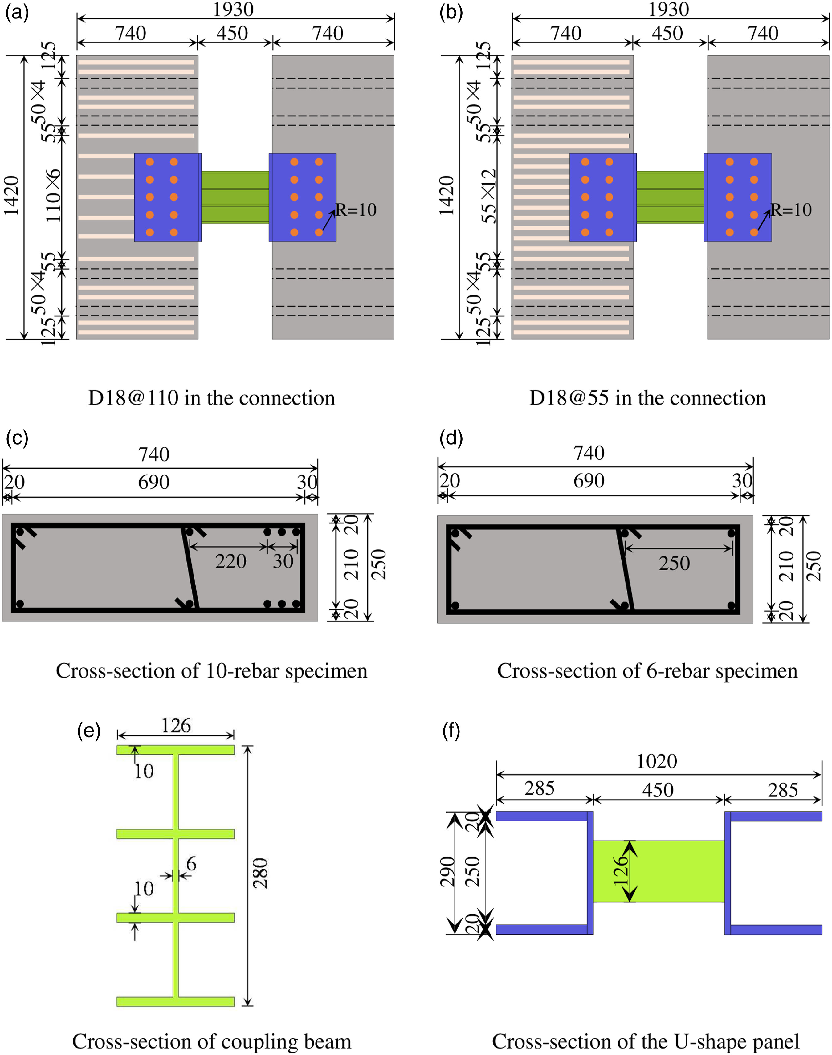
The HCW consists of a replaceable U-shaped steel CB and two wall piers of 740 mm (length) × 250 mm (thickness) × 1520 mm (height). A standard HCW U-4-110 which consists of 4 D18 vertical rebars, D18@110 horizontal rebars in the connection, and a D12@50 stirrup along the height was designed according to the Chinese Standard GB 50010–2010 (Standardization Administration, 2010a). To achieve the replaceable requirements, another two HCWs with higher reinforcement ratios were designed according to the standard specimen, enhancing the seismic behavior of the connection. To protect the concrete in the connection from crushing or spalling, a concrete cover of 30 mm was adopted on the wall pier adjacent to the connection.
According to the standard wall piers above, a Q345 CB was designed. To improve the energy dissipation capacity, the CB was designed to have a shear failure with e/(Mp/Vp) < 1.6 (1.13 being taken in this study) (Li et al., 2018), where e is the length of the CB, Mp is the plastic moment of CB, and Vp is the plastic shear of CB. Meanwhile, to prevent the local buckling of the CB, the flange and web should, respectively, meet the following requirements (AISC 2010): bf/2tf < 0.31 (E1/fy1)0.5 and h/tw < 3.05 (E2/fy2)0.5 where bf is the flange width, tf is the flange thickness, h is the overall depth of the CB, tw is the web thickness, E1 and E2 are, respectively, the Young’s moduli of flange and web, and fy1 and fy2 are, respectively, the yield strengths of flange and web. The maximum clear spacing of stiffeners (dmax) should not exceed the value of 30t w -h/5. Thus, the CB of 410 mm (length) × 126 mm (width) × 280 mm (depth) was designed. Two horizontal 10mm-thick stiffeners were welded on the web, dividing the web depth equally (80 mm per panel).
Details of test specimens (dimensions in mm).
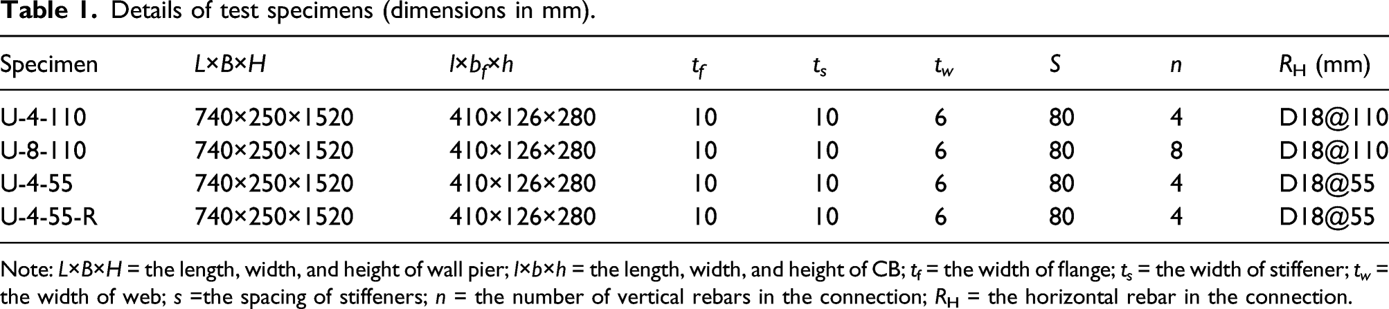
Note: L×B×H = the length, width, and height of wall pier; l×b×h = the length, width, and height of CB; tf = the width of flange; t s = the width of stiffener; t w = the width of web; s =the spacing of stiffeners; n = the number of vertical rebars in the connection; RH = the horizontal rebar in the connection.
Explanation of specimen designation: Taking U-4-55-R as an example, “U” is a standard symbol for specimens, “4” denotes the number of vertical rebars in the connection, “55” indicates the spacing of horizontal rebars in the connection in mm, and “R” represents the replaced specimen.
Material properties
Material properties.
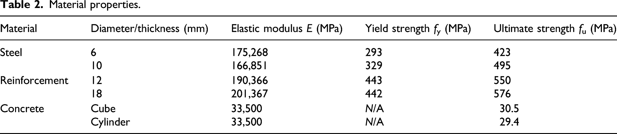
Three plain concrete cubes (150 mm × 150 mm × 150 mm) and three prisms (150 mm × 150 mm × 300 mm) were tested following the Chinese Standard GB/T 50081–2019 (Standardization Administration 2019) to determine the 28-day compressive strength and elastic modulus of concrete. The measured material properties are given in Table 2.
Test setup, loading procedure, and instrumentation
Fig. 3(a) depicts the details of the test setup. The specimen was connected to the load frame through four pretensioned rods. The frame columns were truly pin-connected to the strong floor and girder, giving a constant shear V and reverse curvature bending along the CB. The reversed load was applied through a 200-t hydraulic jack pinned horizontally on the reaction wall. Test setup, loading system, and instrumentation. (a) Test setup. (b) Loading system. (c) Instrumentation.
A displacement loading protocol controlled by the chord rotation was used in the test, as shown in Figure 3(b). The loading was repeated twice at each level to study the stiffness and strength degradation. When the applied load drops below 85% of the peak load or when the inelastic chord rotation reaches 0.2 rad, the specimen is deemed failing.
To capture responses during the test, a series of strain gauges, displacement transducers were installed, as shown in Figure 3(c).
Test results and discussion
Failure modes
All test specimens display failure in web fracture (a brittle failure), as shown in Figure 4 along with the shear force-relative displacement (V-U) hysteretic curves. Failure modes and V-U hysteretic curves. (a) U-4-110. (b) U-8-110. (c) U-4.55.
Figure 4(a) shows the failure mode and V-U hysteretic curve for standard Specimen U-4-110. When chord rotation of the CB θ ≤ 0.013 rad, only a few tiny cracks were developed in the connection. Then, a small panel sliding was observed between the CB and wall piers, followed by a strength increase due to strain hardening. When θ ≥ 0.03 rad, the concrete cover in the connection was gradually crushed under the reverse cyclic loading, resulting in an obvious pinch on the V-U hysteretic curve. Finally, the web fractured at θ = 0.20 rad, followed by a rapid strength deterioration. The panel sliding at the corner exceeded 10 mm, and an obvious concrete crushing was observed in the connection. The CB apparently acts as a fuse and provides a stable V-U hysteretic curve during the test, giving a good energy dissipation capacity.
The primary difference between Specimen U-8-110 and Specimen U-4-110 is the increased vertical reinforcement ratio in the connection. As shown in Figure 4(b), Specimen U-8-110 has a similar failure mode to Specimen U-4-110. During the test, a relative panel sliding between the panel plate and wall pier was observed at θ = 0.07 rad, followed by a gradual concrete cover crushing in the connection. Then, the web fractured at θ = 0.20 rad, followed by a rapid strength deterioration. An obvious concrete crushing was observed in the connection after the test. Additionally, the relative sliding between the two components is much smaller than the standard HCW; and the V-U hysteretic curve is much fuller with no obvious pinch observed during the test, indicating a significantly increased energy dissipation capacity by the increasing vertical reinforcement ratio.
The primary difference between Specimen U-4-55 and Specimen U-4-110 is the increased horizontal reinforcement ratio in the connection. Figure 4(c) shows a similar failure mode to a standard HCW. A relative panel sliding was observed at θ = 0.01 rad. Then, the concrete in the connection was gradually crushed under the increasing applied load. At θ = 0.20 rad, Specimen U-4-55 failed in web fracture. The V-U hysteretic loop is stable in the early loading stage and then an obvious pinch appears after the concrete crushing.
Through the comparison of failure modes and V-U hysteric curves for the test specimens, the CB is shown to act as a fuse during the test. Meanwhile, the ultimate inelastic chord rotation is 0.20 rad which well exceeds the limit of 0.08 rad as specified in the AISC 341-10 (2010), displaying an excellent deformation capacity. Additionally, the energy dissipation capacity can be significantly enhanced through the increase of the vertical reinforcement ratio in the connection. However, no obvious increase of energy dissipation capacity was observed when increasing the horizontal reinforcement ratio. The concrete cover in the connection was crushed for all test specimens and an obvious sliding was observed between the CB and wall piers. This is mainly because the force applied to the anchor bars is too small to resist the panel sliding. Thus, high-strength anchor bolts can be useful to avoid this problem.
Replacement process
After removing the failed CB, the wall piers cannot be restored vertically and there may exist a small dislocation between the two wall piers. The locations of bolt holes can be determined through the terrestrial laser scanning (Zhou et al., 2021), with the automated locating process shown in Figure 5. Then, a new CB considering the relative wall dislocation can be fabricated. Process for automated locating of bolt holes.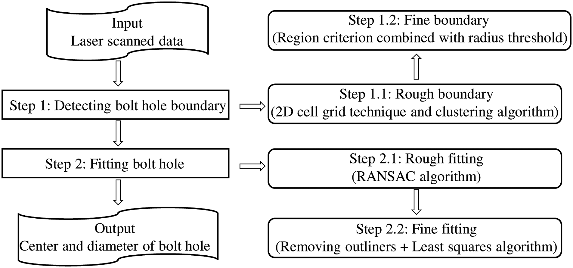
Figure 6 depicts the reinstallation process of HCW, which can be divided into four steps: (1) The CB and panel plates can be precisely fabricated in the factory according to the details of bolt holes (taking about half day); (2) to simplify the reinstallation process, the plates at both ends and on one side of CB can be welded before transporting to the laboratory; (3) then, the other two panel plates can be welded one by one after installing the bolts, as shown in Figure 6; and (4) after transporting to the laboratory, two workers spend about 2 h to complete the reinstallation process. Process for reinstalling the CB.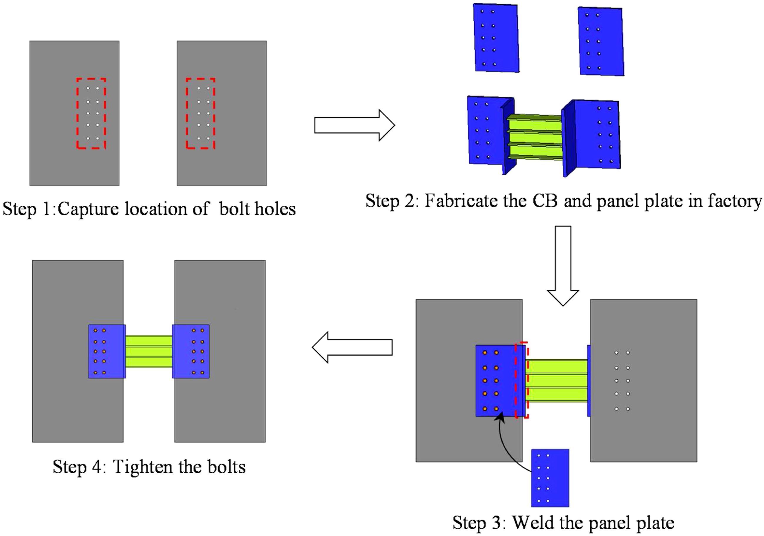
Failure mode for the replaced HCW
Figure 7 shows the failure mode and V-U hysteretic curve for replaced Specimen U-4-55-R. After replacing the CB, a significant gap between the CB and wall pier was noticed as the concrete cover spalled off the original HCW. The CB cannot dissipate energy before engaging with the wall pier; thus, causing an obvious pinch on the V-U hysteretic curve. The concrete cover was further crushed and bending deformation was observed at both ends of the CB under the increasing cyclic load. At θ = 0.20 rad, an anchor bar on the left wall pier was pulled off, caused by the large bending deformation of the CB. Meanwhile, a significant relative sliding at the corner was observed. After the test, obvious friction signs on wall piers in the connection were noted. Despite the chord rotation exceeding the limit of 0.08 rad specified in the AISC 341-10 (2010), the energy dissipation capacity is rather poor due to the concrete crushing in the connection. To improve the energy dissipation capacity of the replaced HCW, high-strength grouting can be used to repair the concrete cover before replacing the new CB. Meanwhile, high-strength anchors can be used as an alternative to resist the panel sliding. Failure mode of U-4-55-R.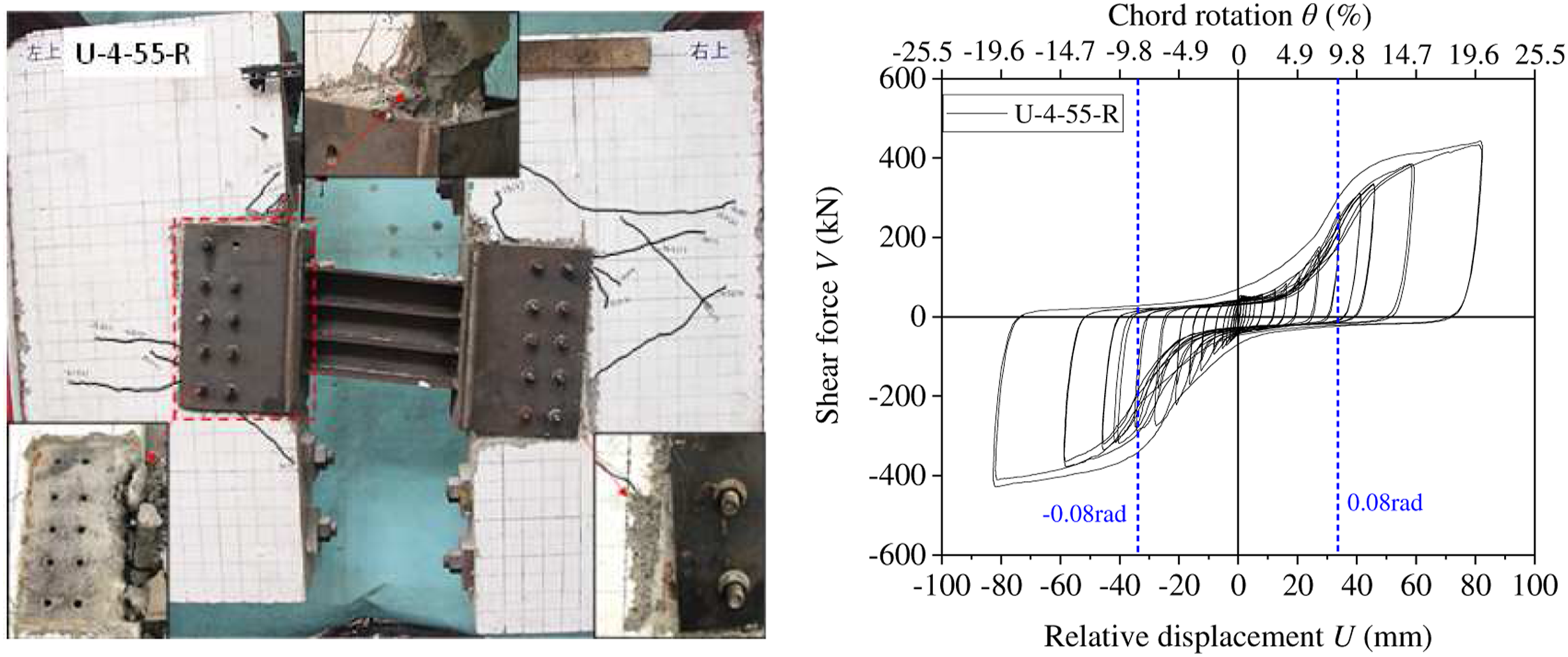
Shear force versus relative displacement skeleton curves
Figure 8(a) shows the shear force (V) versus relative displacement (U) skeleton curves. The main test results including yield shear (Vy), peak shear (Vp), ultimate shear (Vu), and the corresponding relative displacements (Uy, Up, and Uu) are listed in Table 3 where the Vy values were determined through the energy method (Park 1988) shown in Figure 8(b). Moreover, the ultimate state of the test is defined as the one when the load decreases to 0.85Vp; and the ductility factor μ is defined as μ = Uu/Uy, which was used to characterize the ductility of the specimen. V-U skeleton curves and the energy method. (a) V-U skeleton curves. (b) Energy method for the skeleton curves. Measured characteristic factors. Note: The value with the * sign implies that the ultimate load Vu does not decrease to 0.85Vp.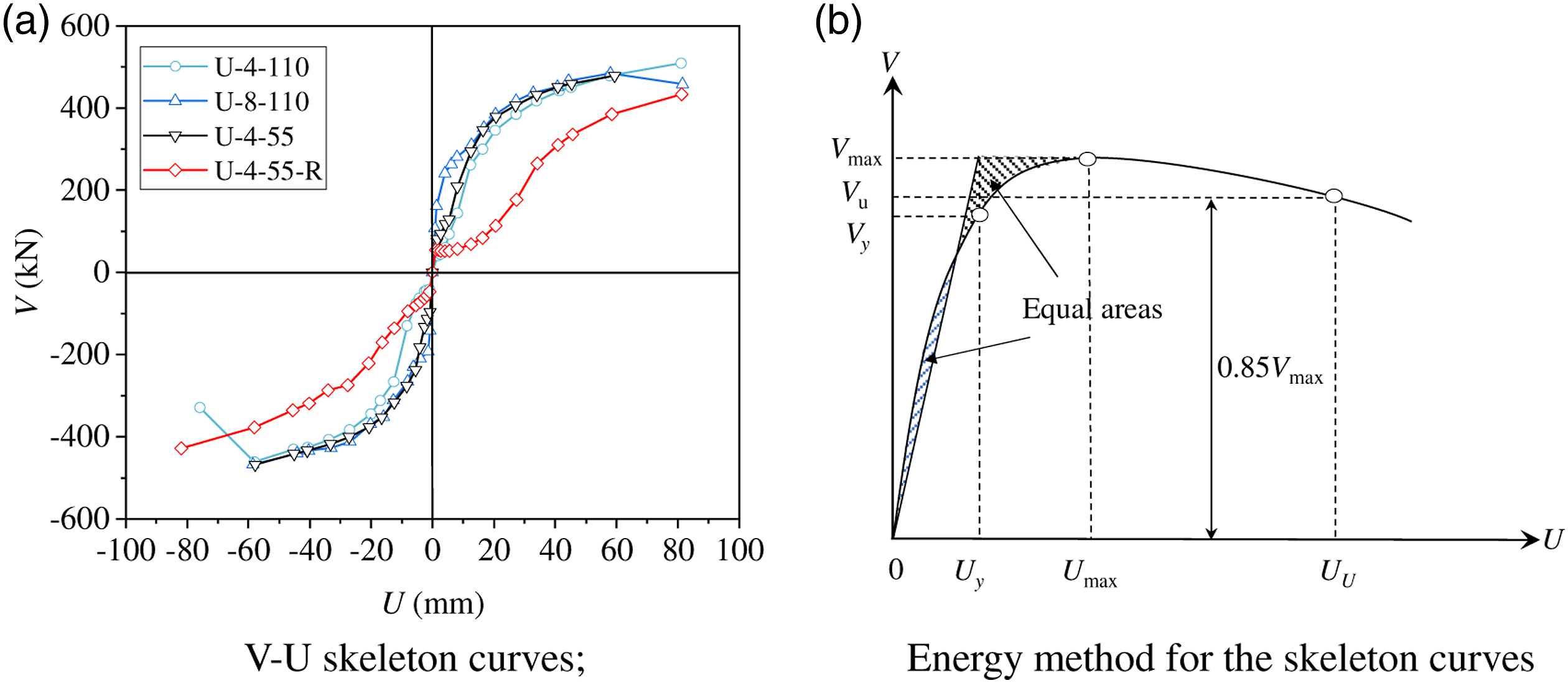
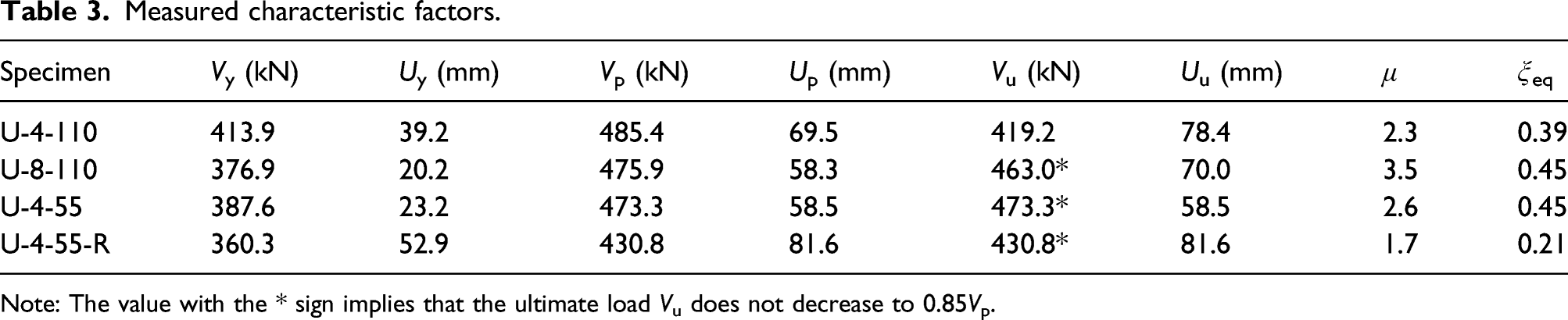
The obtained V-U skeleton curves reveal the following: (1) There are three distinct stages (elastic, elastic-plastic, and damage stage) on each curve of HCW with Specimen U-8-110 showing the greatest initial stiffness and the replaced HCW having the poorest V-U curve; (2) all V-U curves display similar trend before failure; (3) compared with the standard Specimen U-4-110 (Vp = 419.2 kN, μ = 2.3), the Vp and μ values increase by 10% and 52%, respectively, with increasing the vertical reinforcement ratio (Specimen U-8–110), while those values increase by 13% and 13%, respectively, with increasing the horizontal reinforcement ratio (Specimen U-4-55); (4) after replacing the steel CB, the skeleton curve for Specimen U-4-55-R is significantly lower than that of the original CWS (Specimen U-4-55) and the Vp and μ values are 0.93 and 0.50 times those of Specimen U-4-55.
Stiffness and strength degradation
The stiffness and strength degrade due to the crushing of the concrete cover and the plastic deformation of the CB. To quantify the degree of degradation, the averaged circumferential stiffness (Kj) and strength degradation coefficient (η
j
) in two load directions are adopted, as expressed, respectively, by equations (1) and (2)

As shown in Figure 9(a), Kj values decrease rapidly initially and then decrease until the failure of the specimen. This is mainly due to the crushing of concrete cover under the cyclic loading. Specimen U-8-110 shows the largest initial stiffness Kj which is approximately 5.1 times and 2.1 times that of Specimen U-4-110 and Specimen U-4-55, respectively. Additionally, the Kj value of replaced HCW is 30% of that of the original one owing to the gap between the CB and wall piers. Stiffness and strength degradation curves. (a) Stiffness degradation curves. (b) Strength degradation curves.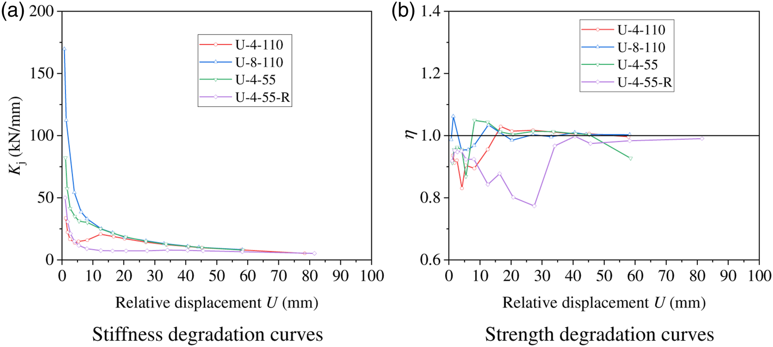
As shown in Figure 9(b), the degradation coefficient (η j ) values vary sharply in the initial stage, especially for Specimen U-4-55-R. That was because of the formation of concrete cracks in the connection, the crushing of concrete cover, and the significant gap that occurred between the CB and wall pier. After the initial stage, ηj values stabilize until the failure of the specimen.
Energy dissipation
The energy dissipation ability can be described by the equivalent damping coefficient ξeq, defined as (Standardization Administration 2010c) The calculation of ξeq and cumulative energy dissipation. (a) Calculation of ξeq. (b) Cumulative energy dissipation.
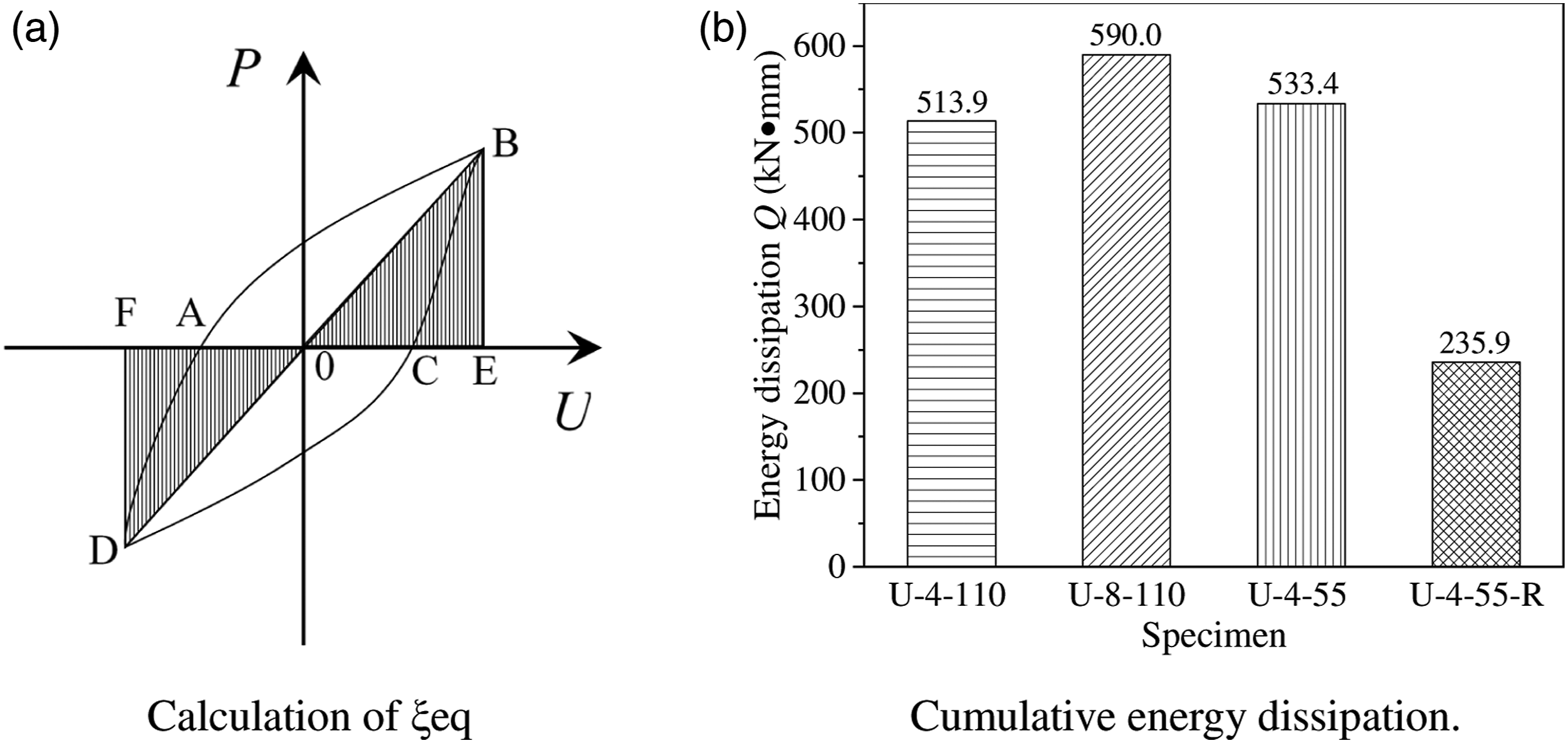
Table 3 lists the ξeq at peak load, ranging from 0.39 to 0.45 for HCWs. Compared to the standard Specimen U-4-110, increasing the reinforcement ratio in the connection can significantly increase ξeq values. The replaced HCW shows a much smaller ξeq value compared with the original one, indicating poor energy dissipation due to the concrete crushing in the connection.
Figure 10(b) shows the cumulative energy dissipation Q. Obviously, increasing the vertical or horizontal reinforcement ratio can increase the energy dissipation capacity, with the former better. The Q value of replaced HCW is only 44% of that of the original one. That is because of the concrete crushing causing a large space between the CB and wall pier. The CB cannot dissipate the energy until contacting the wall piers.
Load versus strain curves
Figure 11 shows the measured strains of steel CB and vertical rebars of Specimen U-4-55 (a representative specimen). Figure 11(a) shows both flanges yield before the web, caused by the bending deformation at both ends of CB. Additionally, the strains along the vertical rebar remain within 500 με in the early stage, while the strains on the upside yield rapidly as the concrete in the connection crushes, as shown in Figure 11(b). This is mainly because the force engaged in the anchor bars is insufficient to ensure the two structural components work compositely. Thus, high-strength anchor bolts can be used to increase the pretension force. The strains obtained from the test (Specimen U-4-55). (a) Steel CB. (b) Vertical rebar.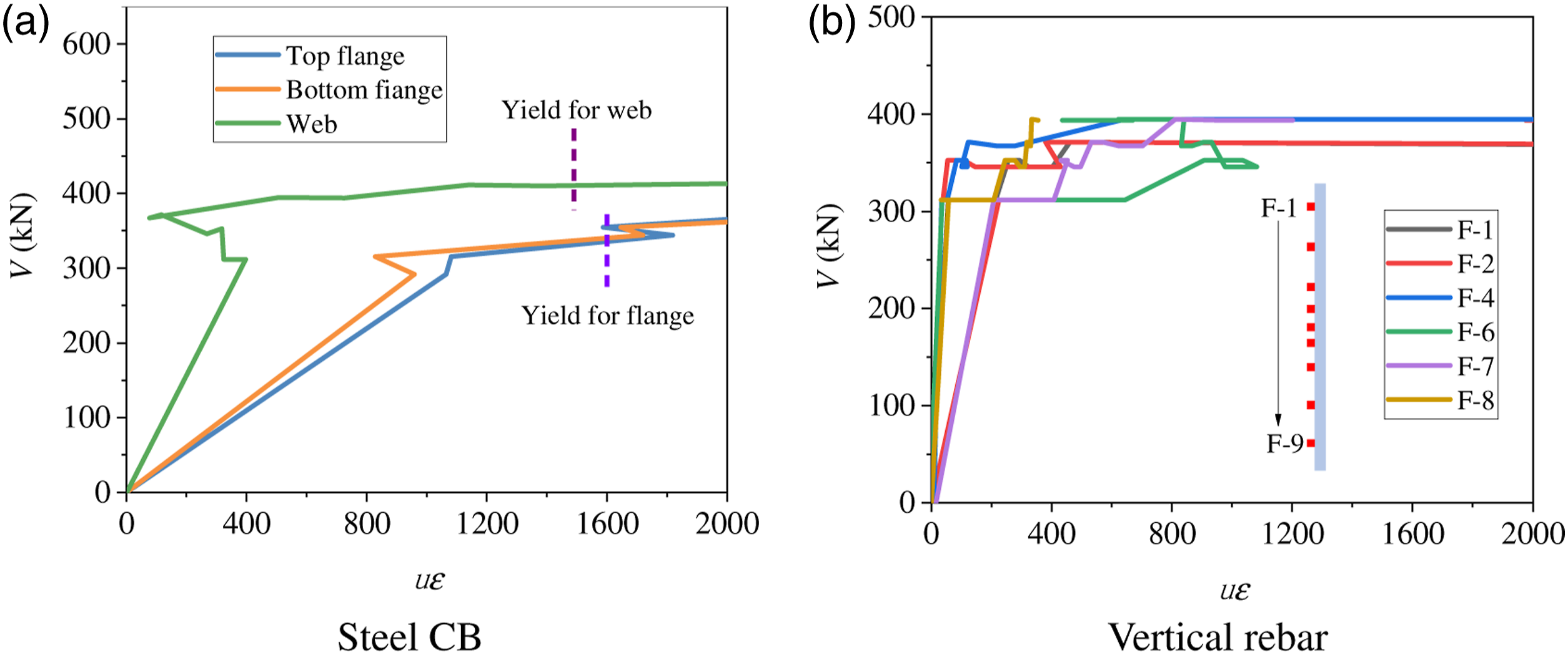
Conclusions
Three full-scale virgin HCWs with replaceable U-shape steel CB were designed and tested under cyclic loading. Additionally, the precise locations of bolt holes after the test were determined using terrestrial laser scanning; and a replaced HCW was also tested. The failure mechanism and seismic behavior were investigated. Based on this study, the following findings are given:
All virgin HCWs fail in web fracture, and the CB acts as a fuse to dissipate the energy satisfying the design concept. The failure mode of the replaced HCW U-4-55-R is the pull-off of the anchor bar, which is caused by the unpatched concrete cover in the virgin Specimen U-4-55-R.
All origin test specimens show an excellent chord rotation of 0.2 rad which well exceeds the code-specified inelastic threshold of 0.08 rad, exhibiting an excellent energy dissipation capacity. Compared with Specimen U-4-110 (a standard specimen), increasing the reinforcement ratio in the connection can greatly increase the ductility and energy dissipation capacity for HCW. Increasing the vertical reinforcement ratio can also significantly increase the initial stiffness.
The method to capture the precise bolt hole locations after the test through the terrestrial laser scanning is shown to be feasible, and the total reinstallation process can be finished in 2 h with two workers in a laboratory.
Compared with the virgin Specimen U-4-55, the seismic performance including strength and energy dissipation capacity of the replaced HCW (Specimen U-5-55-R) is much poorer due to the unpatched concrete cover.
To improve the seismic behavior of replaced HCW, high-strength grouting is suggested to repair the concrete cover in the connection; and the usual anchors can be replaced with the high-strength ones.
Footnotes
Declaration of conflicting interests
The author(s) declared no potential conflicts of interest with respect to the research, authorship, and/or publication of this article.
Funding
The author(s) disclosed receipt of the following financial support for the research, authorship, and/or publication of this article: This research is supported by the National Natural Science Foundation of China (Grant No. 51890902 and 52008055) and Fundamental Research Funds for the Central Universities (Grant NO.2021CDJQY-016).
Data availability
Some or all data, models, or code that support the findings of this study are available from the corresponding author upon reasonable request.
