



Abstract
For the development of underground structures toward large-scale, long-span, and complex structural styles, comprehensive seismic mitigation and controlling measures that consider reducing internal forces together with controlling lateral structural deformation and upgrading energy consumption are significant for improving seismic performance and enhancing resilience of underground structure. For this purpose, a self-centering energy-dissipation column base, which originated from the concept of earthquake resilient structures in aboveground space, is proposed for the framed underground structures in this study. To verify the effectiveness of self-centering energy-dissipation column base, three-dimensional time history analyses are conducted on a single-story double-span subway station. The analysis results show that the self-centering energy-dissipation column base effectively decreases the internal forces of central column and the peak and residual values of story drift and column drift are also minimized about 4%–5%. Meanwhile, it is found that a cyclic opening–closing exists at the column base during an earthquake and the uplift of column returns to zero at the end of the earthquake. It means the self-centering effect of the column base is achieved as expected. Moreover, replaceable energy-dissipating devices provide supplementary energy dissipation to relieve the development of structural plasticity and the uplift behavior of column base avoids the occurrence of plastic hinge. As a result, the structural damages are effectively reduced after the earthquake.
Keywords
Introduction
Recently, with the occupancy of aboveground space tending to be saturated, underground space is gradually being exploited on a large scale. Furthermore, the underground structure develops toward large-scale, long-span, and complex structural styles. For instance, the rail transit system in Shanghai Hongqiao integrated transportation hub is quite complicated, where five subway lines built on railway lines and a large-span space structure intersect. Shanghai World Expo Axis, which covers a vast area of 180,000 m2 in underground space, is the hub connecting the stations of Metro Line 7 and Line 8 and four major venues of World Expo. Meanwhile, according to several scientific analyses of global seismicity (Ammon et al., 2010; Engdahl and Villaseor, 2002; Michael Andrew, 2011), major earthquakes occurred much frequently worldwide in recent years, such as the M8.0 Wenchuan earthquake of China in 2008 (Zhao et al., 2009), the M9.0 Earthquake of East Japan in 2011 (Koseki et al., 2012), the M8.1 earthquake of Nepal in 2015 (Sharma et al., 2016), and the M7.8 earthquake of Ecuador in 2016 (Goretti et al., 2017). Historical earthquake damages, especially serious damages to subway stations and running tunnels in Kobe earthquake in 1995, indicated that underground structures are also vulnerable to severe earthquake events (Iida et al., 1996). Obviously, the tendency of structural complexity and the frequent occurrence of large earthquakes make it urgent to develop more efficient and convenient measures to improve seismic performance of underground structures.
So far, seismic isolation bearings and dampers, which originated from structural vibration control concepts for aboveground structures, have been applied to underground structures to mitigate the seismic responses. Suzuki and Katsukawa (2001) proposed a new seismic isolation of slip-type for underground structures, which coated particular silicone paints on the outer surface of underground structures. An earthquake-resistant structural system for underground box culvert-like open-cut tunnel, in which a mechanical equipment used for absorbing horizontal and rotational displacements was placed on joints between upper slab and columns, was proposed and studied (Endoh et al., 1996). Chen et al. (2014) found that shear panel damper could improve the seismic performance of underground structures by reducing maximum shearing force of central column, while maximum lateral displacement of central columns tends to be magnified to a small degree.
In general, all the abovementioned studies have reduced structural internal forces at varying levels, with insufficient consideration of deformation control ability. Reducing internal forces, controlling structural deformation, and energy consumption are not combined comprehensively. Unignorably, most underground structures are costly, poorly recoverable after earthquakes, and difficult to repair due to the harsh geological environment (Huang and Xiong, 2017; Parra-Montesinos et al., 2006; Xiong and Huang, 2017). Therefore, it is necessary to focus on a comprehensive consideration of controlling lateral structural deformation, reducing seismic forces, and better energy mitigation to accelerate the recovery of large-scale underground structures after earthquakes and decrease property loss and casualties.
On the contrary, owing to a longer history of research in seismic mitigation and isolation in aboveground structures, it has been recognized that there is a need not only to reduce seismic forces of inputting the structure but also to control the lateral deformation in suitable range to allow the structure to be restored without repair or minor repairs. Based on the abovementioned requirements, the concept of earthquake resilient structure has been a new direction to improve structural seismic performance. For this purpose, the rocking wall, the rocking frame, the self-centering structure, or replaceable structural members have been some important structural forms to realize post-earthquake resilience (Mander and Cheng, 1997; Priestley and Macrae, 1996; Priestley and Tao, 1993; Roh and Reinhorn, 2010; Wada et al., 2009). However, the existing achievements and theories of the earthquake resilient structure in aboveground structures cannot be directly used in underground structures. This is mainly because that their vibration characteristics are obviously different, and the construction technique and investment differ simultaneously. The vibration deformation of underground structures is mainly confined by surrounding soils. As a result, the magnitude of deformation subjected to earthquake is clearly smaller than that of aboveground ones. The large rigid body rotation deformation referred to as “rocking” behavior cannot be achieved on the underground structures, whereas a reasonable design can help to realize small-scale lifting and rotation of structures through the self-centering structural form, which concentrates majority of structural damage in replaceable energy-dissipation devices and decrease the residual deformation. In addition, the structures in subspace confronted with severer construction environment and higher investment and cost when compared with those in aboveground space. This requires higher safety redundancy.
In view of the above, a new form of self-centering energy-dissipation (SCED) column base is proposed. The form newly introduced is targeted to decrease seismic responses and endow the central column with a capacity of self-centering to diminish the residual deformation after earthquakes. In addition, it has slighter damage at column base for being equipped with a replaceable energy-dissipating device at the foot. Taking a typical single-story double-span subway station as the case, shown as Figure 1(a), a three-dimensional non-linear dynamic time history analysis has been conducted. The difference in dynamic responses of central column, components of SCED column base, and the whole structure with and without SCED column base are analyzed. Then, the effectiveness and mechanism of SCED column base in the framed underground structure are discussed.

Underground structure with SCED column base: (a) total view of whole structure, (b) top view, and (c) side view of SCED column base (unit: mm).
Introduction to SCED column base
Components and behaviors of SCED column base in vibration
The SCED column base is a new column base form, which is composed of a self-centering component (unbonded pre-stressed tendons), additional energy-dissipating devices, and a load-bearing element (reinforced concrete column), as illustrated in Figure 1(b) and (c). For highlighting the components of SCED column base, the traditional longitudinal reinforcements are omitted in Figure 1(b), plotted in detail in Figure 5. The central column is a pre-cast concrete member. The column is fixed and integrally cast with the top beam, while assembled with the bottom beam by unbonded pre-stressed tendons, longitudinal reinforcements, and energy-dissipating devices. The upper and lower ends of tendons are anchored to the top and bottom beams, respectively. The column base’s sectional size is minimized partially, with additional energy-dissipating device installed here.
The main functions of SCED column base for seismic mitigation to central column are self-centering and energy dissipation (Figure 2). The self-centering mechanism mainly relies on the restoring forces derived from unbonded pre-stressed tendons, self-weight, and the overlying soil pressure, namely
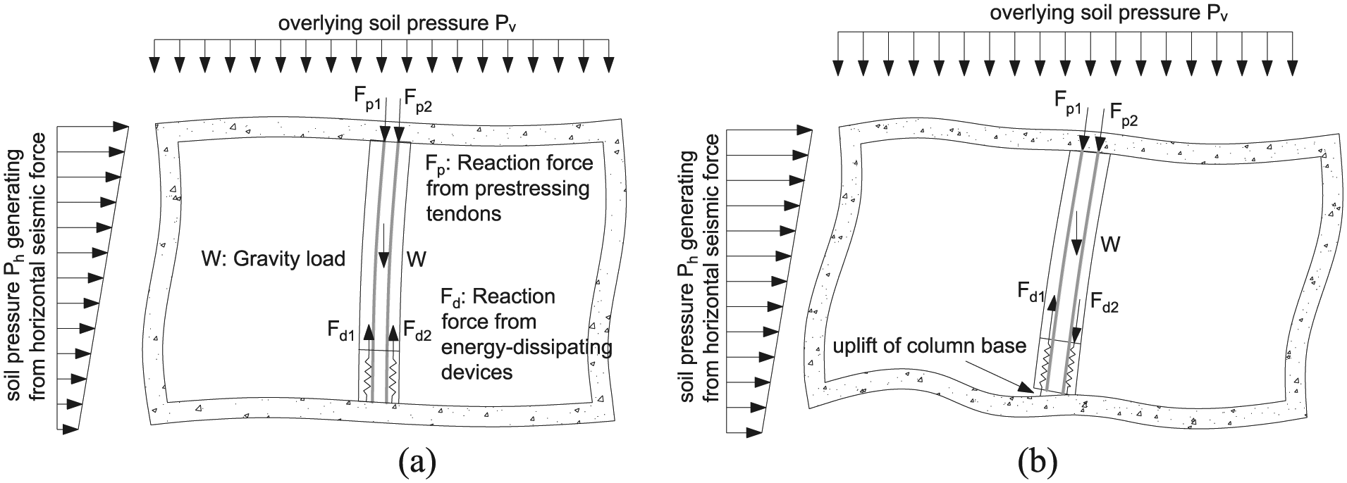
Behaviors of SCED column base during earthquakes: (a) non-lifted state and (b) lifted state.
Energy dissipation mostly depends on supplementary energy-dissipating devices and the plastic deformation (another energy-dissipating manner) of central column itself. When the horizontal forces applied to the central column are smaller than the critical loads of rotation, the column is at the non-lifted state. Vertical frictional energy-dissipating devices only participate in the vertical load bearing and rely on the small bending deformation of the central column to generate energy dissipation. The central column has not been into plastic phase or its plastic energy dissipation is negligible. In reverse, when the horizontal loads are larger than the critical loads of rotation, central column starts to rotate and uplift around certain node of bottom section. With column’s cyclic lift and recovery, energy-dissipating devices generate damping moment to hinder the uplift or recovery of column and take the first place to enter yielding state, which delays the yielding of central column. In summary, the energy-dissipating devices always stay in the state of energy consumption.
Simulation methods of SCED column base
Unbonded pre-stressed tendons
Figure 3(a) and (b) shows the elements used and locations of unbonded pre-stressed tendons in numerical modeling. Post-tension unbonded pre-stressed tendons are modeled by truss elements, which simulate the feature of only axial force transmitted in real tendons. On one hand, the tendons are placed in pre-buried pipes in reality, which means the exterior surfaces of tendons and interior surfaces of concrete are not directly contacted. For simplicity of numerical computation, pre-buried pipes embedded in concrete are not modeled in this case. Also, there is no need to consider the adhesive force between exterior surfaces of tendons and interior surfaces of concrete. On the other hand, the tendons can slip along the pipes so that no constraint of axial translation is imposed on them. Considering radial confinement of pipes in real conditions, tendons stay at a constant transverse location by using spring elements of infinite axial stiffness to connect the nodes of tendons and nodes of concrete in modeling. Both ends of each pre-stressed tendon are anchored in beams. Therefore, the anchorage relationship is modeled by means of tie constraint, which makes the translational and rotational motion equal for anchor points and the ends of tendons. The pre-stressing force is defined by initial stress condition.

Schematic diaphragms of simulation methods: (a) central column with SCED column base, (b) unbonded pre-stressed tendons, (c) uplift of column base, and (d) energy-dissipating devices.
Uplift of column base
To simulate uplift of column base, a contact interaction is defined at the interface of the central column and the bottom beam as Figure 3(c). It may satisfy the following conditions. First, free uplift of column is allowed at the column base. Then, the contact interface algorithm should be able to transmit stresses between column base and bottom beam. For this reason, hard contact is defined to fulfill the normal behavior of the contact interaction, which means that normal stress exists between the bottom beam and column base when in contact and allows for separation after contact. The tangential behavior of the contact interaction is simulated using Lagrange multiplier algorithm with a frictional coefficient of 0.5. Namely, no relative motion is allowed between two closed surfaces until the equivalent shear stress reaches the critical value. The critical value is determined as follows

where µ is the frictional coefficient, 0.5 assumed in this case and P is the normal pressure at the contact interface.
Energy-dissipating devices
Energy-dissipating devices are modeled by combining horizontal connectors and vertical connectors together to consider translational motions in two directions, illustrated in Figure 3(d). The simplified constitutive model of vertical connectors assumes the bilinear kinematic hardening rule. It is noted that
Modeling
Prototype structure of research
The prototype structure is the typical single-story two-span framed underground structure—Daikai station. Daikai station was constructed between 1962 and 1964 by the cut and cover method. It is also the first subway structure completely collapsed, widely used in studying failure mechanism of underground structure and having rich comparative data (Huo et al., 2005; Iida et al., 1996). The structural configuration form and transverse sectional size of station in destruction area are the same as actual conditions of Daikai station, plotted as Figure 1. It was observed that after earthquakes the ends of some central columns were crushed to damage like a lantern shape.
Finite element model
A finite element model is established by the general-purposed commercial code ABAQUS (2014), with a horizontal width of 136 m (eight times of structural width) and a vertical height of 58 m, as shown in Figure 4. The longitudinal length of 3.5 m, which is equal to real column spacing, is adopted to guarantee that there is always one column in the longitudinal section of the model. The ground surface is assumed to be free. The horizontal and vertical displacements at bottom boundary are both fixed, while the displacements in the longitudinal direction are confined simultaneously. The boundaries at both sides of the model are set as infinite element conditions to minimize the influence of seismic inflection. All boundaries are supposed to be undrained.

Numerical model.
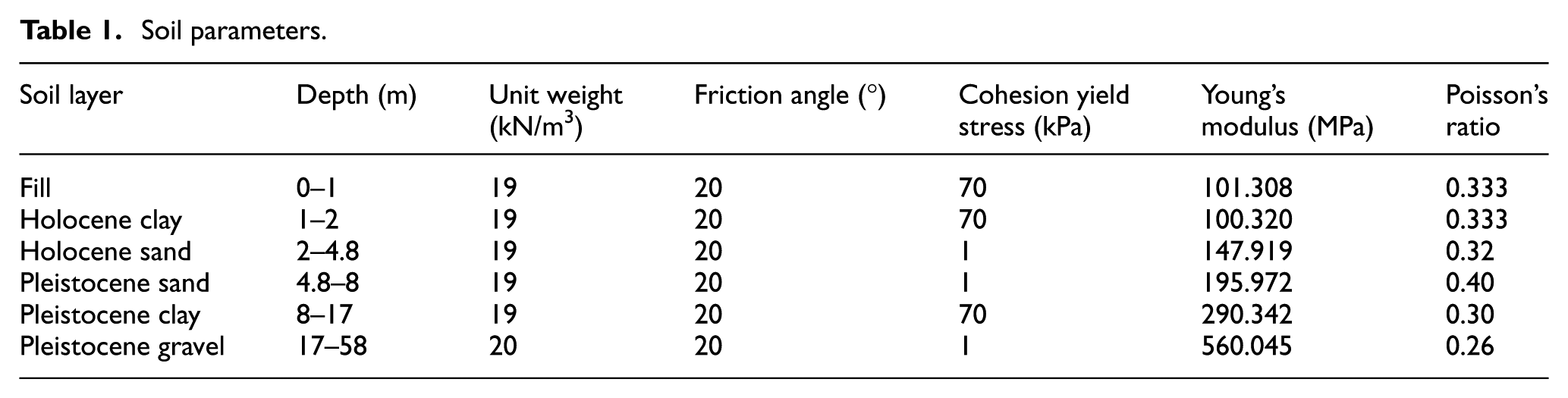
A total of 5260 eight-node reduced integration solid elements C3D8R are used to simulate soils. The stress–strain relationship is assumed to follow the Mohr–Coulomb model. The soil layers and parameters in borehole D-1 and B-3 of destruction area are utilized for modeling, as listed in Table 1. A total of 3096 eight-node reduced integration solid elements C3D8R are used to simulate the structure. The structure without central column is supposed to be ideal elastoplastic material, while concrete damaged plasticity model is utilized for concrete in the central column. The whole structure has a unit weight of 25 kN/m3, Poisson’s ratio of 0.2, and Young’s modulus of 33,683.3 MPa. The key parameters of concrete damaged plasticity constitutive are initial compressive yielding stress 24.0 MPa, extreme compressive yielding stress 34.3 MPa, and maximum tensile stress 3.1 MPa.
Soil parameters.
Traditional longitudinal reinforcements in the central column are reckoned to be ideal elastoplastic, with a density of 7800 kN/m3, Poisson’s ratio of 0.3, Young’s modulus of 200 GPa, and a yielding stress of 235 MPa. Meanwhile, the constitutive relationship of pre-stressed bars is supposed to be the bilinear hardening model. The bars have a density of 7850 kN/m3, Poisson’s ratio of 0.3, and Young’s modulus of 205 GPa. Important parameters of the bilinear hardening model are as follows: initial yielding strength and yielding strain are 980 MPa and 0.0048, respectively, and extreme strength and extreme strain are 1270 MPa and 0.0350, respectively.
The mesh sizes of soil vary from 0.94 m×0.70 m×0.50 m to 7.70 m×0.70 m×11.00 m. The mesh density near the structure is refined. Figure 5 shows an apparent single bias defined from lateral infinite element boundary to structure. The interaction between soils and the structure follows the Mohr–Coulomb law. Referring to the research of Huo et al. (2005), the frictional coefficient µ is taken as 0.4, equivalent to a frictional angle of 22°. The cohesive force between soil and structure is not considered.

Sectional configuration at both column ends: (a) elevation, (b) cross section 1–1, and (c) cross section 2–2 (unit: mm).
Design parameters of SCED column base
In the detailed configuration of both column ends shown in Figure 5, the section of column base has smaller size in contrast to the top section of column. They have different longitudinal widths, 0.5 and 1.0 m, respectively. There are two bunches of pre-stressing bars in the central column’s section, with a sectional area of 400 mm2 for each one. They are arranged away from two edges of column 0.1 m transversely, located in sectional center longitudinally. In order to ensure the column’s elastic restoring force and uplifting ability within the threshold value of code (GB 50010-2010), the initial tension stress of pre-stressed tendons is controlled as 508 MPa, equal to 50% of extreme strength. The layout of traditional longitudinal reinforcements in the central column remains as the Daikai station, and the stirrups and hooping are not considered. Initial sliding force, elastic stiffness, and damping ratio of additional energy-dissipating devices are 50 kN, 100 kN/mm, and 0.4, respectively.
Analytical step and input accelerations
Two steps are involved in this analysis. First, geostatic procedure is carried out to balance the gravity load. Initial geostatic stress is exactly equilibrated and zero deformation is set. Then, dynamic analysis will be carried out with input accelerations.
Figure 6 presents the horizontal and vertical components of the accelerations, which is recorded from strong ground motion observation at Port Island in Kobe earthquake in 1995. The maximum values of horizontal and vertical accelerations are 0.58 and 0.16 g, respectively. It needs to be clarified that the spatial variation in ground motions determines the input methods of ground motions (Bi and Hao, 2012; Huang and Wang, 2015a, 2015b), which has some effects on the seismic responses. But according to the Eurocode 8 (ENV 1998-2: 2005), structures with a length of less than 200 m do not need to take this factor into consideration. The dimension of the model here is not beyond this range. Therefore, the spatial variation in input accelerations is not considered in the numerical analysis. What also needs to be mentioned is that both acceleration records decrease to less than 0.04 g 20 s later. To reduce calculation time, the accelerations are truncated to be a record of previous 25.0 s for carrying out time history analysis. The accelerations are input from the bottom boundary, which is the artificial bedrock face at 58 m from the ground surface.
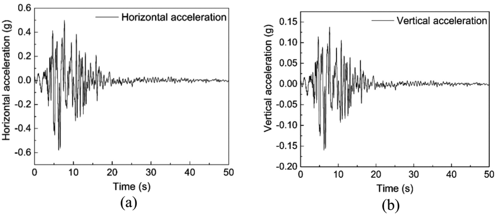
Input accelerations.
Results and discussion
Great achievements have been obtained on the failure mode of Daikai as well as the cause of Daikai station after Kobe earthquake in 1995. It was commonly believed that shear or shear-bending failure of the central column led to the collapse of the overall structure. That is, the central column, due to its poor deformation capacity and deficiency of shear resistance, destroyed prior to side wall. The destruction of central column caused the collapse of the roof slab and then resulted in the overall collapse of the structure.
Therefore, the central column is the key factor of seismic mitigation control. The focuses are put on the deformation capacity and bearing capacity of the central column and the components of SCED column base. The seismic responses with and without SCED column base are compared to evaluate the effectiveness and reliability of this new method to improve seismic performance.
Seismic responses of the whole structure
Horizontal story drift
The story drift is defined as the difference between horizontal displacements at middle points of a bottom slab and an adjacent top slab, representing the racking deformation of the whole structure. Comparison between story drift of the structure with or without SCED is shown in Figure 7. It can be seen that the story drift is decreased a bit than that of structure without SCED column base, deserving to be mentioned, the decrease becoming more and more significant as seismic excitation weakens. The peak values of story drifts without and with SCED column base are 76.7 and 73.5 mm, respectively. It means the maximum story drift is reduced 3.2 mm, about a decline of 4.2%. Moreover, the residual deformation of story drift changes from 68.5 to 64.8 mm, a reduction of 3.7 mm, and about a drop of 5.3%.
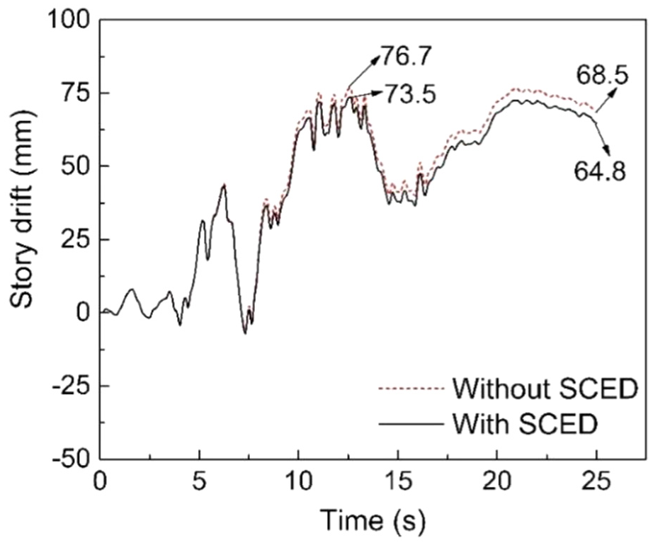
Horizontal story drifts of the whole structure.
In summary, with SCED column base adapted, the maximum horizontal story drift is slightly reduced than before, and the residual one also falls a little. Through analysis, the tendency of a reduction in story drift is attributed to the following factors. First, it is already recognized that the unbonded pre-stressed tendons have evenly distributed deformation and no stress concentration between two anchor points (Iemura et al., 2004). Combining the feature of high strength with uniform small deformation, all tendons are still in an elastic state even when traditional longitudinal reinforcements come into yielding. The superposition of elastoplastic behavior of concrete and unbonded pre-stressed tendons’ constant elasticity enlarges post-yield stiffness of whole structure. Therefore, a larger post-yield stiffness brings about a smaller deformation when the structure comes into yielding (Iemura et al., 2004; Sakai and Mahin, 2004; Zatar and Mutsuyoshi, 2002), which means a lowering of horizontal story drift with the seismic excitation approaching the end moment. Second, pre-stressed tendons take advantages of their excellent elastic restoring ability to pull the structure back into the original place, which helps to reduce the residual story drift.
Seen from the research results of Chen et al. (2014), when the shear panel damper as a passive energy-dissipating device was introduced into underground framed structure, the internal forces drop dramatically, while the lateral deformation of the whole structure increased a little owing to the lowering of structural stiffness. However, the story drift of the whole structure falls slightly with SCED column base, which benefits to control structural residual deformation after earthquakes. As a result, the control of structural story drift makes it more possible for restoring structures or reduces recovery time.
Maximum structural plastic deformation
Figure 8 shows the mechanism of relieving structural plastic deformation of the structure with SCED column base by comparing with the traditional capacity design and the self-centering column base design. The reason why the plastic deformation of four connection areas between side walls and adjacent slabs decrease a lot is that the energy-dissipating devices installed at column base dissipate much structural plastic energy, delaying the occurrence of yielding and plastic behavior. While for central column, besides the beneficial action of energy-dissipating devices, the features of availability of uplift and no tension allowed at bottom section avoid the generation of plastic hinge at column’s bottom end in cyclic seismic loading. Specifically, the maximum equivalent plastic strain of the central column with the SCED column base falls from 0.006302 to 0.003477, and for four connection areas it drops from 0.004462 to 0.001557. Clearly, the development of plasticity is relieved, and the avoidance of plastic hinge at column base increases the possibility of restoring the central column.
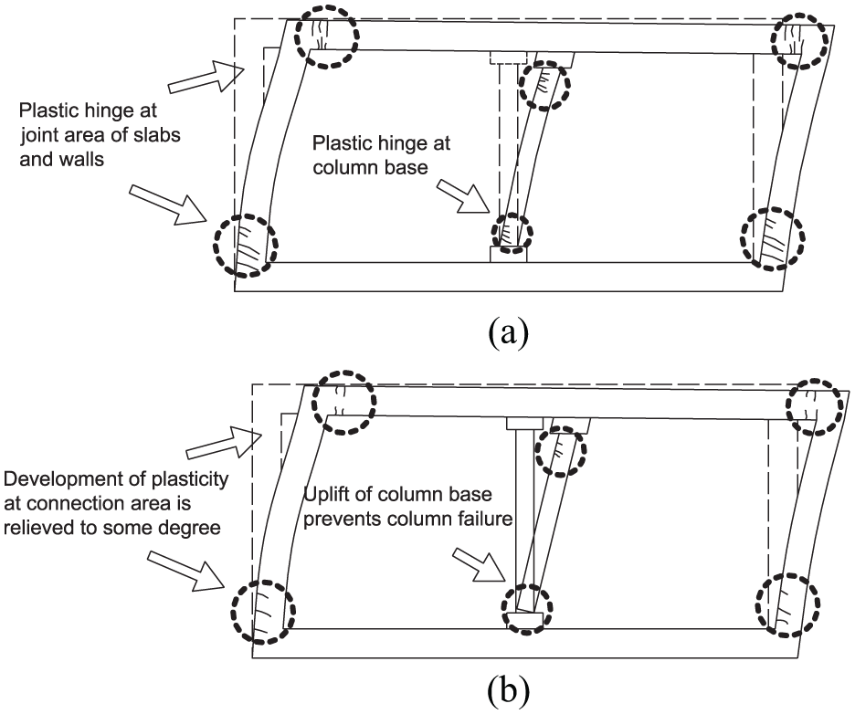
Mechanism of relieving structural plastic deformation: (a) traditional capacity design and (b) self-centering column base design.
Seismic responses of the central column
Internal forces of the central column
Post-earthquake survey found that column base and connection area of column and adjacent top beam always suffered severe damage compared to the other portions. Hence, attention would be paid first to the internal forces at these portions to evaluate seismic behavior of the structure and its members. Figure 9 shows the time history curves of internal forces with and without the SCED column base.
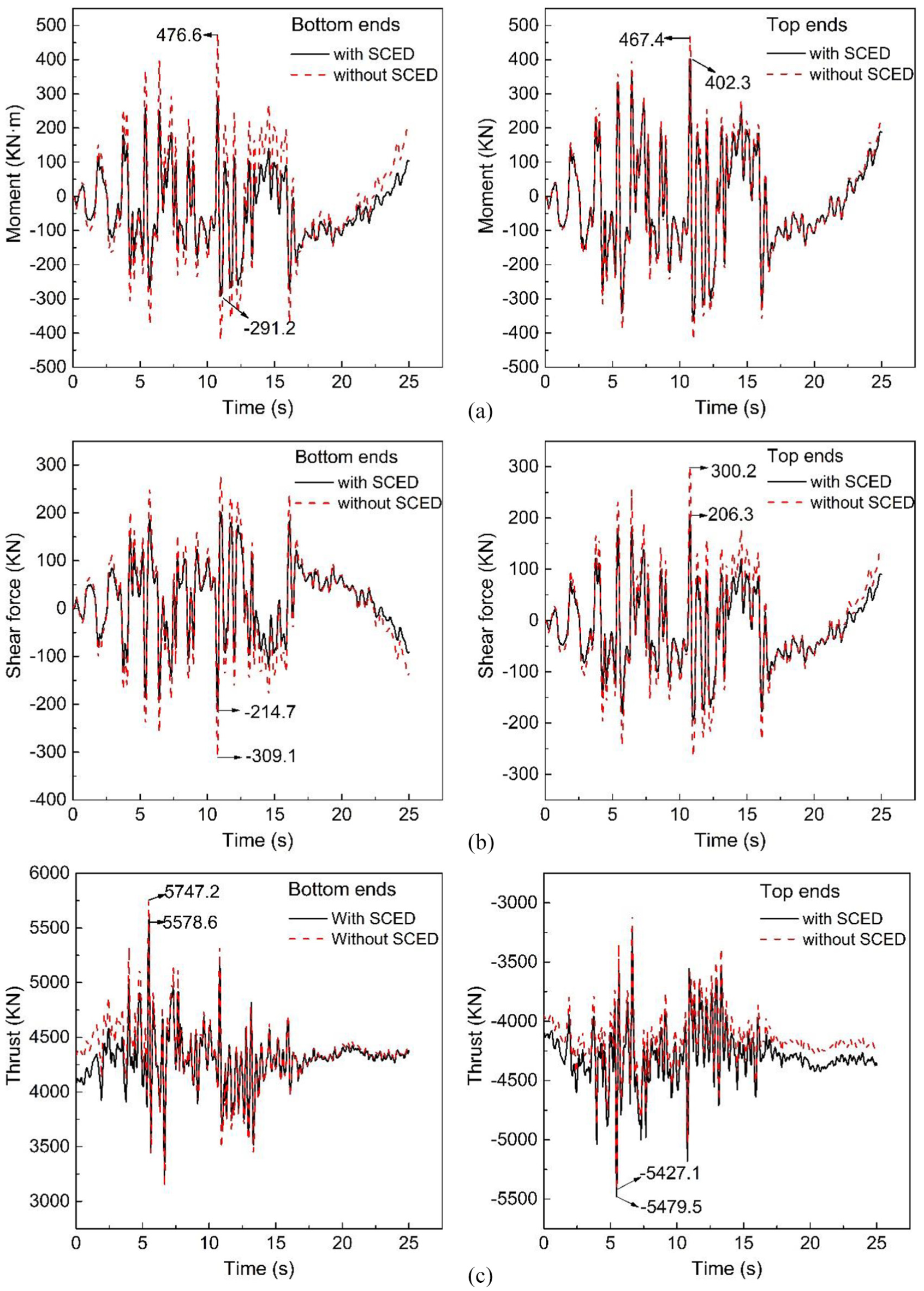
Comparisons of internal forces of central column: (a) moment, (b) shear force, and (c) thrust.
Specifically, the sectional moment time history curves are displayed in Figure 9(a). Without SCED column base, the moments at bottom and top ends are 476.6 and 467.4 kN m, respectively. Correspondingly, the moments of two ends drop to be 291.2 and 402.3 kN m after adopting SCED column base. It means that the peak moment of column’s bottom end is decreased about 38.9%, while for column’s top ends it cuts back approximately 13.9%. As shown in Figure 9(b), the shearing forces of both column ends fall sharply with SCED column base. The maximum shearing force of bottom end falls from 309.0 to 214.7 kN, a drop up to 30.5%. Correspondingly, the peak shearing force of top ends is reduced from 300.2 to 206.3 kN, 31.3% smaller than the structure without SCED column base.
Obviously, the abovementioned results indicate that the SCED column base has significant superiority in minimizing seismic moment and shear force. First, this is because the column’s bottom section is weakened by means of reducing size, which means the lateral stiffness of central column is weakened by this configuration. Second, the ability of uplift at column base changes the connection pattern from a rigid connection to a semirigid connection. Consequently, more horizontal seismic action is transferred to the stiffer members of whole structure instead of the central column, and a semi-rigid connection bears less shear force and moment than a rigid connection. Therefore, internal forces directly proportional to horizontal seismic action are reduced effectively, including sectional moment and shear force. The reason why the sectional moments at top and bottom ends of column have a significant difference in efficiency of seismic mitigation is that pre-compression force on top ends of column from unbonded pre-stressed tendons generates overturning moment, which counteracts partial of reduced moment. While for the bottom one, the pre-compression force does not act on it due to its non-fixed connection with bottom beam (Figure 1(c)).
Figure 9(c) compares the sectional thrusts of both column ends. After adapting SCED column base, the thrust is substantially equal to the structure without SCED column base. On one hand, the maximum thrust at top ends is increased by 52.4 kN equivalent to a variation of 0.97%. On the other hand, the maximum thrust at the bottom end is reduced by 168.6 kN equal to a drop of 2.93%. Obviously, the variation range is insignificant compared to the thrust which is larger than 5500 kN. A negligible increase in thrust at column’s top ends is owing to the reverse pre-compression due to pre-stressing tension of tendons, whereas the energy-dissipating devices undertake a part of thrust for column’s bottom end, which brings about a small decrease in sectional thrust for the bottom one.
Bearing capacity analysis of column ends
To evaluate the effectiveness and safety of SCED column base, the combination of internal forces at column ends is also analyzed. Based on the parameters of materials and layout of reinforcements in the numerical analysis, the theoretical thrust moment-bearing capacity curves of different sectional sizes are obtained. Since the concrete material strength in numerical simulation is larger than in real Daikai station, the theoretical bearing capacity curve calculated in this case has a wider range than that of real structure. Therefore, although in real structure the internal forces were beyond bearing capacity which resulted in failure, the combination of internal forces without SCED column base in Figure 10(a) and (b) is still within safety range here. Meanwhile, it is demonstrated in Figure 10(a) that the combinations of dynamic internal forces at the bottom end with SCED column base are always within the safety range, despite that the width of column’s bottom section is minimized which lowers the bearing capacity, Most importantly, the dynamic internal forces with SCED column base in Figure 10(a) and (b) are both distributed at a smaller region than that of structure without seismic mitigation processing. It means a larger safety redundancy is achieved in the retrofitted structure with SCED column base.
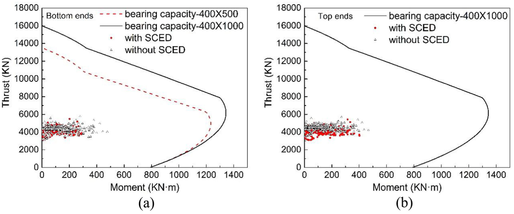
Thrust–moment relationship of cross sections at: (a) bottom ends and (b) top ends of central column.
Horizontal column drift
Figure 11 compares relative horizontal displacements of two column ends between the structure with and without SCED column base, which is termed column drift. It is indicated that horizontal column drift decreases more and more significantly with the acceleration records near the end. Without SCED column base, the maximum and residual value of horizontal column drift reaches 47.95 and 39.68 mm. After adapting SCED column base, the peak value is 45.98 mm equivalent to a drop of 4.1%, and the residual one is 37.68 mm about a reduction of 5.0%. Therefore, the reduced column drift facilitates the replacement of energy-dissipating devices and post-earthquake recovery, which enhances the structural resilience.
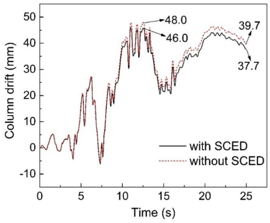
Horizontal column drifts.
Compared with the results of Figures 7 and 11, the column drift has the same variation tendency as the story drift. Through analysis, the reasons why the column drift are reduced are almost the same as that of the story drift. Briefly, according to the analyses of related studies (Iemura et al., 2004; Sakai and Mahin, 2004; Zatar and Mutsuyoshi, 2002), the post-yield stiffness of reinforced concrete structures is almost zero. Unbonded pre-stressed tendons make the post-yield stiffness of reinforced concrete column more stable and larger than before, which reduces the residual and maximum displacements of reinforced concrete column. Moreover, it is known that the yield stresses of unbonded pre-stressed tendons have a high strength, with a yield stiffness of 980 MPa and an extreme stiffness of 1270 MPa. The high-strength unbonded pre-stressed tendons do not yield, which provides effective elastic restoring force to pull the structure back into original place. To summarize, the reduction in column drift is mainly attributed to a stable larger stiffness and effective restoring force after the installation of unbonded pre-stressed tendons.
Seismic responses of components of SCED column base
Stress of pre-stressing tendons
One key factor of realizing self-centering function is that the pre-stressed tendons stay in an elastic tensile state. Figure 12 illustrates that at first the axial stress of tendons gradually decreases from initial stress due to pre-stressing loss and then maintains remains around 475 MPa. Hence, pre-stressing tendons always stay elastic and tensile, ensuring that elastic restoring force is large enough to pull the structure back into the original place.
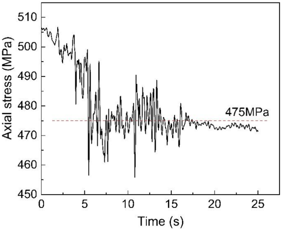
Axial stress of pre-stressed tendons.
Uplift of column base
Figure 13 describes the uplift of column’s bottom end. It can be seen that the opening of column base is extremely small before the 5th second when the acceleration is not noticeable. In this condition, the bottom joint is equivalent to that of a rigid joint. With accelerations becoming gradually larger, the uplift occurs because the moment of column’s bottom end exceeds overturning moment. It is demonstrated that when the peak acceleration reaches 0.58 g at about the 6.5th second, the first uplift appears. Then, the connection area opens and closes repeatedly, and the maximum uplift can reach to about 0.98 mm. Finally, self-centering function of unbonded pre-stressed tendons comes into effect to make the connection area of bottom section closed. Based on the above data analysis, the self-centering effect of SCED column base is achieved expectedly.
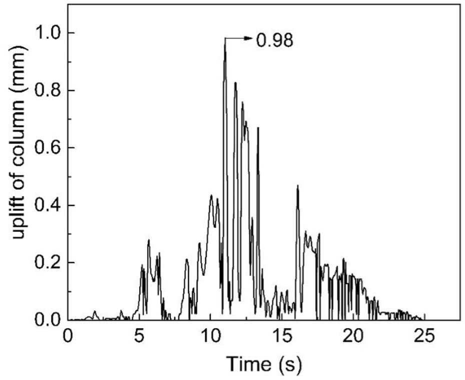
Uplift of central column.
Dynamic behaviors and energy dissipation of additional energy-dissipating devices
As illustrated in Figure 8, SCED column base helps to relieve structural plastic deformation, then plastic energy (i.e. partial seismic energy induced) which is dissipated by the reinforced concrete structure itself would be better to be dissipated by additional energy-dissipating devices. In the presented SCED column base, with the increase in bending deformation and uplift of column, energy-dissipating devices deform plastically in the vertical direction and they dissipate energy. Figure 14 shows the relationship between the thrust and relative displacement vertically. The energy-dissipating devices bear part of thrust of bottom section, a peak value of up to 50 kN, which is also the reason why the column’s thrust of bottom section decreased (Figure 9(c)). Figure 15 shows the plastic energy dissipation of additional energy-dissipating devices. It is also found that the displacement and energy increase dramatically between the 4th and 6th seconds, which matches well with the occurrence of peak values in the strong acceleration records (Figure 6). The peak and residual displacement of energy-dissipating devices is 0.68 and 0.32 mm, respectively. Both are small enough compared with the height of central column. This benefits to replacement of devices.
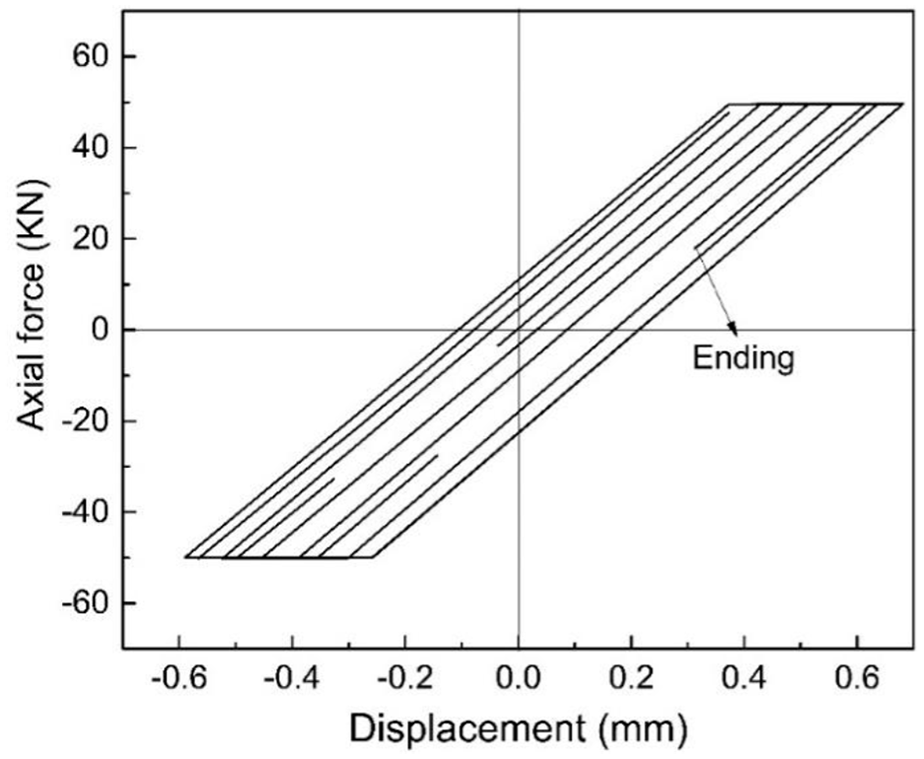
Hysteretic curve of energy-dissipating devices.

Energy dissipation of additional energy-dissipating devices.
Conclusion
The SCED column base is proposed into a framed underground structure in this article. The feasibility and effectiveness of this new structural resilient method are studied through numerical analyses. The following conclusions can be drawn:
SCED column base effectively reduces the seismic force responses of the framed underground structure. In the single-story subway station studied, the shear force and moment are effectively decreased for the weakening configuration of column’s bottom end and a semirigid connection between the bottom beam and the column base. The thrust at column’s top end has an insignificant increase for reverse pre-compression from the unbonded pre-stressed tendons, while that of bottom end can be decreased to some extent because energy-dissipating devices undertake part of pressure under an appropriate design.
SCED column base achieves a good self-centering effect. It is found that the column base circularly opens and closes and is finally back to its original place at the end of earthquake, verifying the self-centering ability of the central column. This is because the unbonded pre-stressed tendons with high strength and uniform strain distribution have great stable restoring forces to pull the column back.
SCED column base plays an active role in controlling lateral structural deformation to some degree. The maximum and residual drifts of central column and whole structure appear to be 4%–5% smaller than that of structure without SCED column base as the seismic excitation approaches the end of earthquake, which is the result of the larger post-yield stiffness of structure and great elastic restoring force of pre-stressed tendons.
The development of structural plasticity has been obviously relieved, and the plastic hinge at the column base is avoided. It is because more plastic energy is dissipated by additional energy-dissipating devices instead of the column itself. Besides, the constraint between the column base and bottom beam is loosen, which endows an ability of uplift to the central column.
Footnotes
Declaration of Conflicting Interests
The author(s) declared no potential conflicts of interest with respect to the research, authorship, and/or publication of this article.
Funding
The author(s) disclosed receipt of the following financial support for the research, authorship, and/or publication of this article: This research was supported by the National Natural Science Foundation of China (Grant Nos: 41472246 and 51778464) and “Shuguang Program” supported by Shanghai Education Development Foundation and Shanghai Municipal Education Commission. All supports are gratefully acknowledged.
