




Abstract
Here, a two-coupling friction system with a multi-phase working mechanism was considered for 10-story buildings. Within the framework of performance-based seismic design, and based on refined fortification levels and target performance, three optimal models were established. The performance parameters of the isolation layer were used as design variables, and the displacement and the acceleration of the seismic response were used as performance objectives of the structure. Furthermore, sequential quadratic programming was used to solve the dynamic optimization problem of the nonlinear isolated structure. The numerical results illustrate that the optimization model, its formulation, and the proposed algorithms are both reasonable and effective. The two-coupling friction system installed at an isolation layer works in stages. The isolation layer meets the various target performances under different design criteria and different seismic action levels.
Keywords
Introduction
Protecting structures against dynamic loads, resulted from strong winds and earthquakes, is one of the prime objectives in structural design (Fallah and Zamiri, 2013: 87–96). In conventional design approaches toward earthquake resistance, the basic priorities are the provision of strength, ductility, and energy dissipation in structural units. However, to increase security, modern design methodologies incorporate control systems. Such systems reduce the structural response during strong seismic motion and ensure minimal damage to the structure. Vibration isolation is generally accepted as an effective technology for the reduction of seismic effects in strategically important structures, such as hospitals, schools, bridges, and nuclear power plants (Chaudhuri and Hutchinson, 2006; Chung et al., 1999; Moroni et al., 1998; Villaverde, 2006). In order to achieve vibration isolation, the structure is decoupled from the horizontal components of ground motion via base isolation between the building and its foundation. Common features are horizontal flexibility and energy dissipation capabilities (Sun and Li, 2010). Horizontal flexibility provides a natural frequency shift toward lower frequencies, away from dominant energy-containing frequencies (Cheng and Chao, 2017).
Despite these advantages, vibration isolation has not been widely used to structures with large height-to-width ratio, large weight, or long natural vibration period, since the isolation layer displacement of such structures is often very large (Lu et al., 2016). Adequate separation distance between adjacent buildings is required to prevent mutual collisions or structural pounding (Jangid, 2000). When the separation distance between adjacent buildings is insufficient, collision will occur, and when the deformation reaches the isolation bearing limit, the building might undergo overall overturning. This will lead to the destruction of both structural and nonstructural components such as hospital instruments and facilities, communication centers, fire stations, and other important structures (Bucher, 2009), causing also enormous losses of lives and properties. Second, with regard to isolation design, the performance objectives of the design are numerous, including reduction of seismic response in preparation for frequent earthquakes, and control of the deformation of the isolation layer and the internal force of bearings in preparation for occasional earthquakes. Ordinary rubber bearings and friction sliding bearings reduce single horizontal stiffness characteristics gradually only, leading to difficulty in meeting the requirements of isolation layer stiffness at different stages. Excessive stiffness reduction of the isolation bearing in preparation for occasional earthquakes is not conducive to the displacement control of the isolation layer. If the stiffness required in the preparation for occasional earthquakes is used in isolation design, due to excessive initial stiffness, the effect of vibration reduction may be greatly reduced. Finally, regarding the performance of isolation devices, in earthquake engineering, the design of seismic isolation devices plays a key role in ensuring structural safety and integrity. On one hand, in order to reduce structural damage, such devices must provide a sufficient level of structural decoupling and energy dissipation. Sufficient stiffness must be provided to prevent excessive deformation or residual offset. Such issues require trade-off considerations. On the other hand, in order to improve the seismic performance of base-isolated buildings and reduce the displacement demand of the isolators, the performance-based isolation optimization is performed (De et al., 2018; De and Ricciardi, 2018a, 2018b, 2018c; Hashimoto et al., 2015; Liu et al., 2013; Tsai, 1995; Yang et al., 1991; Zhao et al., 2019).
A performance-based optimal design has been considered as the main development direction of future seismic design (Li et al., 2003). Its purpose is to effectively control the damage of buildings under the action of earthquakes with different intensity levels, and as a result, to achieve improved performance levels of buildings. The performance-based dynamic optimal design is helpful in improving the reliability of building seismic design, avoiding potential seismic safety hazards, and promoting the development of building design in general (Xu and Dai, 2005). Therefore, performance-based optimal design has attracted the interest of both researchers and designers, and a wide range of related research has been conducted. Among others, the most remarkable result is the formalization of the single need of satisfying performance objectives, such as the mean square acceleration of the isolation system (Inaudi and Kelly, 1993; Jangid, 1996; Liu et al., 2011). The response targets can be combined to obtain a new fitness function as the optimization design objective (Moeindarbari and Taghikhany, 2014). The total cost within the life cycle of the structure (Li et al., 2003) and the stiffness (Liu and Zhou, 2017) have been used as objective functions. However, the optimization design method with a single performance objective cannot meet the different performance requirements of the isolation layer in response to different earthquake levels. Therefore, a multi-objective optimization method for the optimal design of the sliding isolation system, aiming to restrain the seismic response of building structures, has been proposed (Fallah and Zamiri, 2013). Although the restoring device with optimal viscous damper could effectively suppress the structural seismic responses, the performance of the isolation system was reduced.
A friction damper with a coupling mechanism (FDC) has been previously developed (Hori et al., 2013; Ikenaga et al., 2013; Zou et al., 2013). In the preparation for small earthquakes, the horizontal stiffness of the FDC is low, and it increases in the preparation for medium earthquakes or set-strength earthquakes. Thus, achieving a good isolation effect in preparation for small earthquakes, and reducing the overall displacement of the isolation layer and superstructure in preparation for medium earthquakes or set-strength earthquakes are paramount. The mechanism, where friction dampers are connected in stages, meets the requirements of performance-based optimization design. Therefore, in this study, a performance-based dynamic optimal design, based on the sequential quadratic programming (SQP) method, was used to obtain the optimal design of a sliding isolation system. The seismic response of an isolation structure with two-coupling FDCs in a building was analyzed, while the validity of the two-coupling FDCs and the correctness of the performance-based optimization design method were verified. The nomenclature of the physical parameters used in this article is listed in Table 1.
Nomenclature of physical parameters.
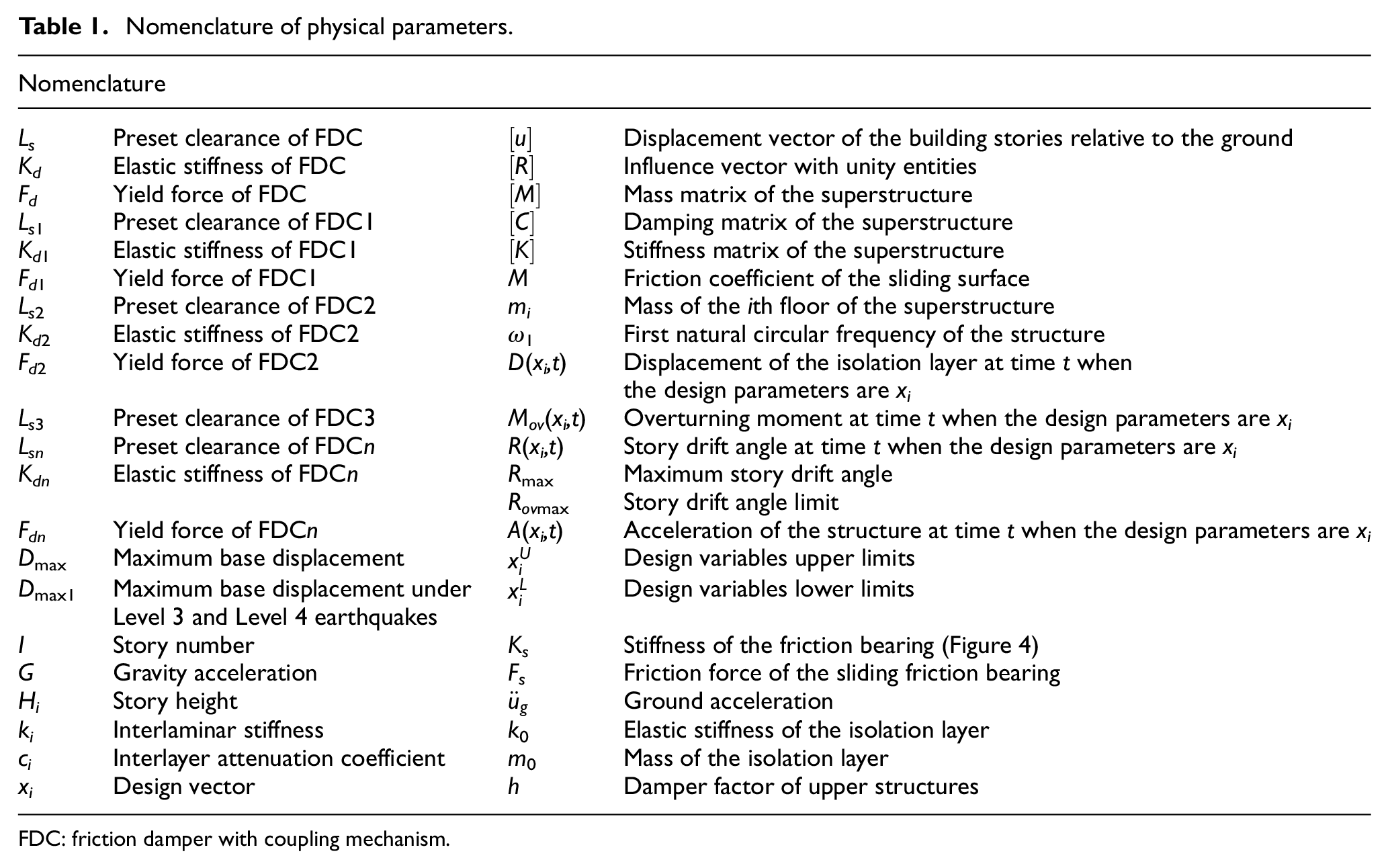
FDC: friction damper with coupling mechanism.
FDC
The FDC
Figure 1 shows a schematic of the FDC. Before coupling occurs, the external damper rod and the coupling mechanism are detached. After the damper deformation reaches the preset clearance, the FDC is coupled and the friction force is transmitted. Coil springs are installed between the friction part and the piston rod of the FDC to absorb the shock caused by the coupling. Once coupling has occurred, the coupling mechanism holds the external rod until the mechanism is manually released (JGJ 3-2002, 2002).
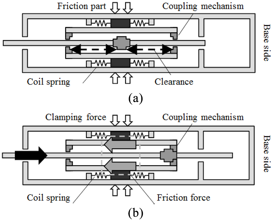
Schematic of the friction damper with a coupling mechanism (a) before and (b) after coupling.
As shown in Figure 2, the friction force and the stiffness are zero. The friction force is not transmitted to the primary structure until the displacement has reached the preset clearance Ls. As soon as the single directional displacement exceeds Ls, the piston rod is coupled with the friction damper, the coupling mechanism does not detach the external rod from the internal rod, and the axial force of the damper increases until it reaches the yield force Fd. After yielding, the stiffness Kd of the FDC is zero.
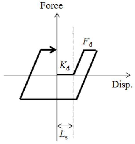
FDC hysteresis curve.
Multiple-coupling FDC
When several FDCs with different preset clearances are installed in the isolation layer, the damping force of the entire isolation layer increases incrementally with the increase in earthquake strength. Dmax represents the maximum base displacement; Ls1, Kd1, and Fd1 represent the preset clearance, the elastic stiffness, and the yield force of the first coupling FDC (FDC1), respectively; Ls2, Kd2, and Fd2 represent the preset clearance, the elastic stiffness, and the yield force of the second coupling FDC (FDC2), respectively; and Lsn, Kdn, and Fdn represent the preset clearance, the elastic stiffness, and the yield force of the n-coupling FDC (FDCn), respectively. The working process of n FDCs in the isolation layer can be divided into n+ 1 different work stages, which are defined as follows:
Before coupling (0 ≤Dmax < Ls1).
No damping force is generated by the FDCs (Figure 3(a)).
First coupling (Ls1≤Dmax < Ls2).
When the damper deformation reaches Ls1 and FDC1 has been coupled, the hysteresis shows a bi-linear shape, which is defined by the coil spring stiffness (Kd1) and the friction force (Fd1) of FDC1 (Figure 3(b)).
Second coupling (Ls2≤Dmax≤Ls3).
After the first coupling, when the damper deformation reaches Ls2, which is the clearance of FDC2, the second coupling occurs and FDC2 begins to generate friction force. The hysteresis has a bi-linear shape, which is defined by the friction forces Fd2+Fd1 and the stiffness of the coil springs Kd1+Kd2 (Figure 3(c)).
…
nth coupling (Lsn≤Dmax).
When the damper deformation reaches Lsn, which is the clearance of FDCn, the nth coupling occurs and FDCn begins to generate friction force. After coupling, the stiffness is Kdn, which is generated only by FDCn. Immediately after unloading occurs, the hysteresis has a bi-linear shape, which is defined by the friction forces Fd2+Fd1+···+Fdn and the stiffness of the coil springs Kd1+Kd2+···+Kdn (Figure 3(d)).
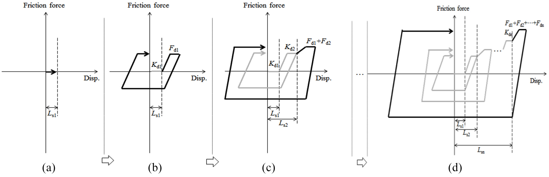
Hysteresis of n different FDC types: (a) before coupling, (b) first coupling, (c) second coupling, and (d) the nth coupling.
Analysis outline
Analysis model
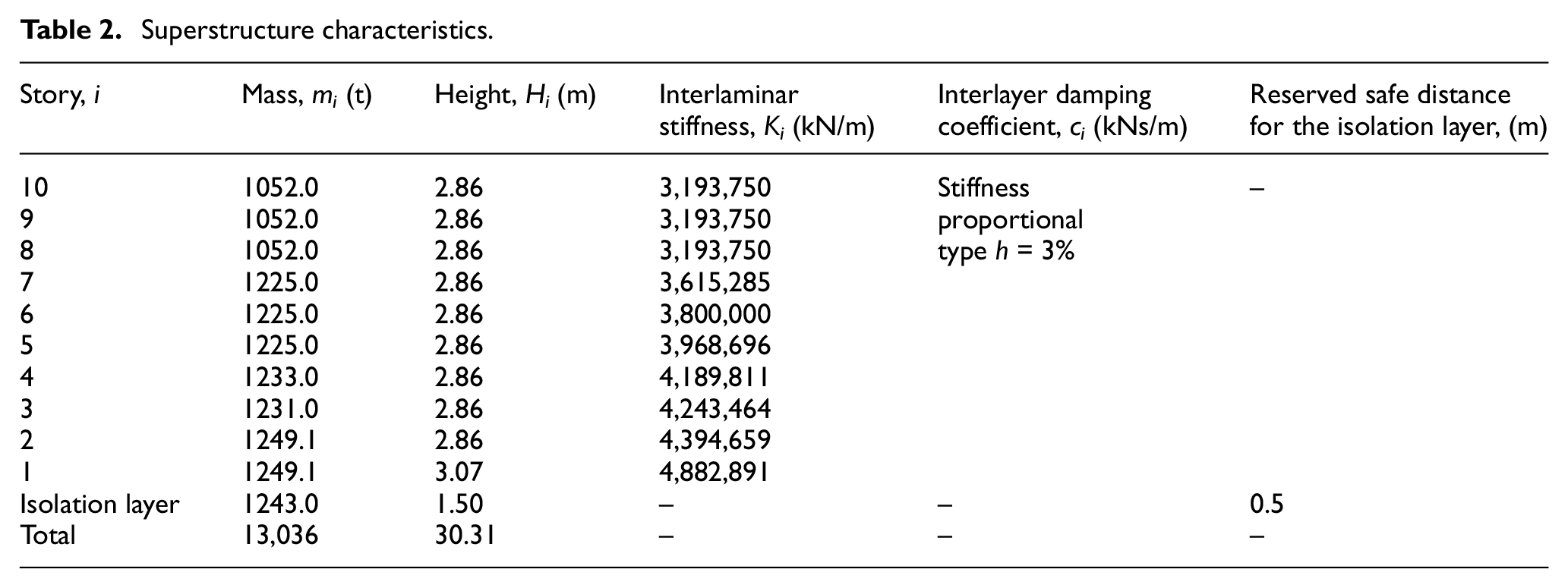
In order to study sliding isolation systems and investigate the effectiveness of the performance-based optimization design method, a 10-story reinforced concrete frame structure was selected, which is supported via sliding isolation equipped with FDCs. For the considered frame, the mass and the stiffness values of the stories are listed in Table 2. The damping of the superstructure was approximated via the Rayleigh proportional damping, mass, and stiffness. A damping factor of 3% was assumed. Before coupling, the structural natural vibration period was 4.3 s. After the first coupling, the structural natural vibration period was 1.42 s. After the second coupling, the structural natural vibration period was 1.4 s. The following assumptions were considered for the modeling:
During an earthquake event, the superstructure remains elastic. This assumption is justifiable, since the purpose of the base isolation is to reduce building responses.
The building is modeled as a shear-type structure with one lateral degree of freedom at each story level.
The friction force provided by the sliding system has ideal the Coulomb friction characteristics, which means that throughout the sliding of the base raft, the friction coefficient at the contacting surfaces remains constant and independent of both velocity and induced pressure.
Superstructure characteristics.
Governing equations
The combined system, shown in Figure 4, is subject to the horizontal ground acceleration. The equation governing the motion of the 10-story structure resting on sliding isolation in a non-sliding state before the coupling phase can be expressed as

where

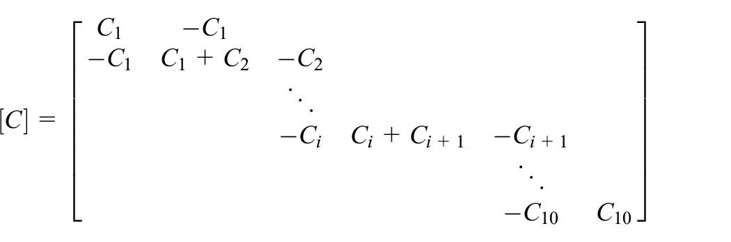
where ci represents the damping of the ith floor of the superstructure, ki represents the mass of the ith floor of the superstructure, ω1 represents the first natural circular structure frequency, and h represents the damping factor. ci can be obtained via the circular frequency of the first vibration of the isolated structure and h through equation (2)

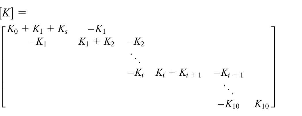
where K0 represents the stiffness of the isolated structure, and Ks represents the stiffness of the friction bearing. The stiffness K0 of the isolation layer differs depending on the different FDC working stages. The effect of FDC on isolation layer stiffness can be described as follows:
Before coupling phase: the FDC does not work. The stiffness of the isolation layer is equal to the stiffness of the friction damper, K0 = Ks.
First coupling phase: the FDC1 begins to work. The stiffness of the isolation layer is equal to the sum of the stiffness of the friction damper and the stiffness of FDC1, K0 = Ks+Kd1.
3 Second coupling phase: the FDC2 begins to work. The stiffness of the isolation layer is equal to the sum of the stiffness of the friction damper and the stiffness of FDC1, and the stiffness of FDC2, K0 = Ks+Kd1+Kd2.

Analysis model.
During the sliding phase and before coupling, the frictional force will be equal to the frictional resistance Fs, which is expressed as follows

where μ represents the friction coefficient of the sliding surface, and g represents the ground acceleration. The frictional resistance acts opposite to the sliding direction. The average acceleration method of β = 1/4 in the Newmark-β method was used to solve the coupled equation (1).
Due to the alternation of the above three working phases, the dynamic behavior of a sliding structure is nonlinear. The motion equations are solved at each time step, and the conditions for the three phases are checked at the end of each time step. According to this procedure, the governing equations are written in the state space form and are solved with a time step of 0.002 s, using a computer code written in MATLAB (9.2(R2017a)).
Performance-based optimal design
In this article, seismic designs were directly developed based on the displacement and the response acceleration of the structure in preparation for earthquake actions. Using the performance parameters of the isolation layer as design variables, the displacements and the accelerations of seismic response were directly adopted as structural performance indicators. Repeated time-history analysis of various seismic waves under different seismic action levels ensures that the performance of the designed structure just reaches the target performance level.
Determination of seismic fortification levels and target performance
In order to achieve multilevel fortification standards and control the damage state of structures subjected to different levels of earthquake action, it is necessary to refine the seismic fortification level in terms of dividing the level of earthquake action, since the performance of the structure is related to its damage state. Both the isolation layer displacement and the response acceleration reflect the structural damage effectively. Therefore, in this design, the isolation layer displacement and the structure response acceleration were used as target performance for dividing the level of earthquake action. Table 3 shows the seismic fortification levels and the target performances under different earthquake conditions.
Seismic fortification levels and target performances.

Input ground motion
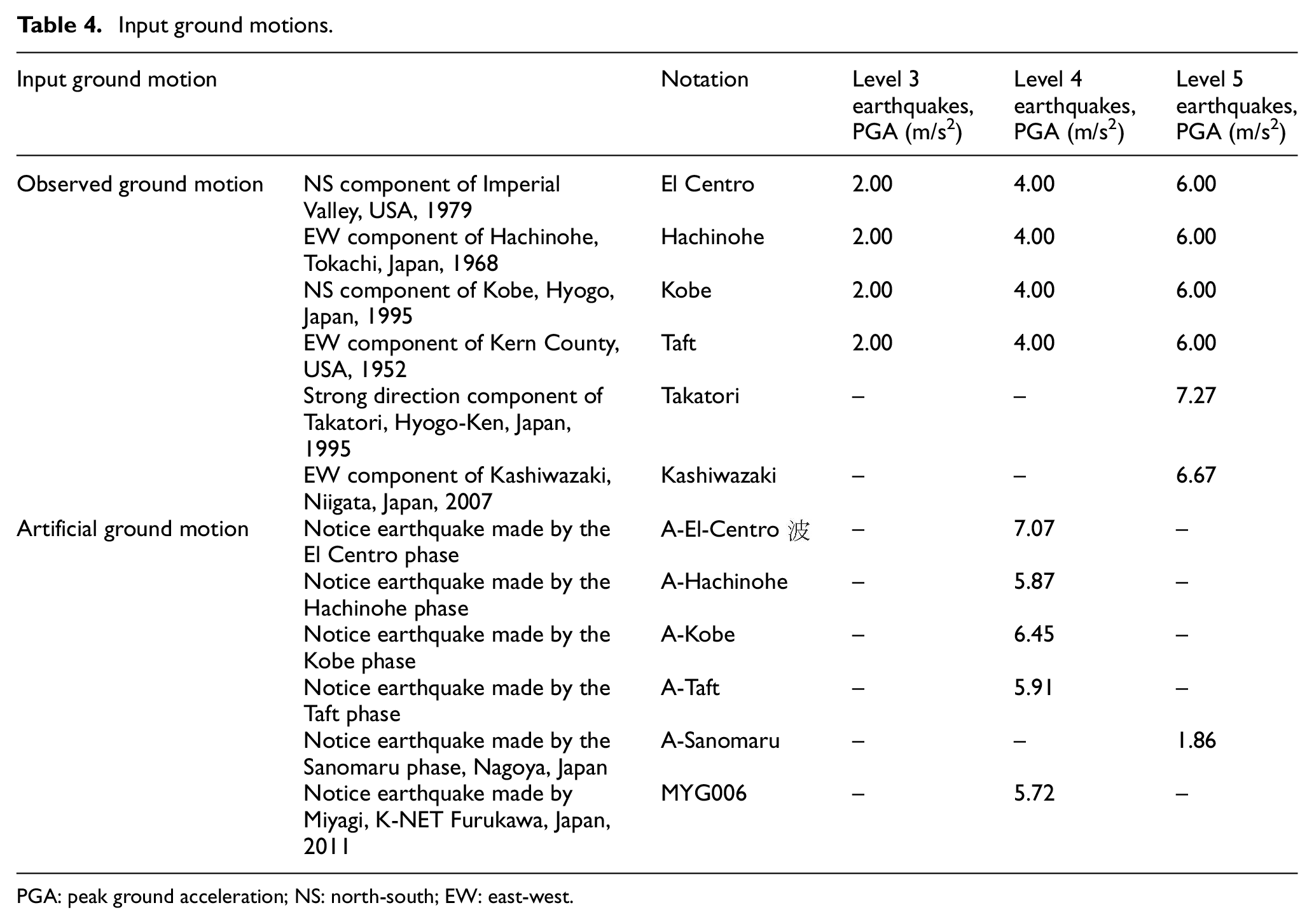
According to the requirements presented in Table 3, the ground motions shown in Table 4 were adjusted. The peak ground acceleration (PGA) of moderate earthquakes corresponds to 2 m/s2. The PGA of large earthquakes corresponds to 4 m/s2 for observed and artificial ground motions. Artificial ground motions are formed based on observed ground motions. The PGA of extremely large earthquakes corresponds to 6 m/s2. Figure 5 shows the acceleration response spectrum of moderate, large, and extremely large earthquakes, where the vertical dotted line indicates the acceleration response of the analyzed isolated structure at its natural vibration period. It can be seen that, under moderate earthquakes, the acceleration response spectrum of the Hachinohe ground motion was the largest. Under large earthquakes, the acceleration response spectra of the Hachinohe and MYG006 ground motions were the largest. Under extremely large earthquakes, the acceleration response spectra of the Hachinohe and Takatori ground motions were the largest. The following time-history response analysis was conducted for the above-mentioned moderate, large, and extremely large earthquakes. The maximum response of the structure under each earthquake input was evaluated.
Input ground motions.
PGA: peak ground acceleration; NS: north-south; EW: east-west.
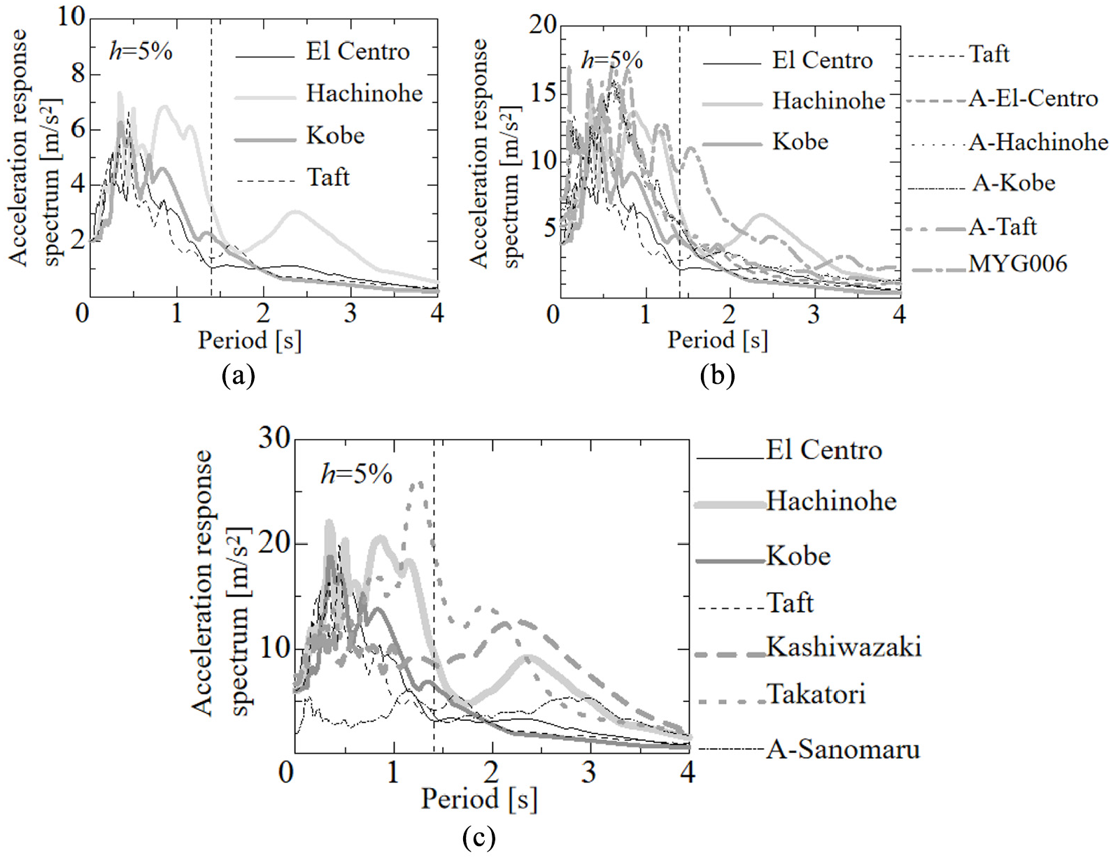
Acceleration response spectrum of input ground motions: (a) moderate ground motion, (b) large ground motion, and (c) extremely large ground motion.
Optimal design model
The entire optimization process is presented in Figure 6. Based on the determination of seismic fortification levels, the target performances described in section “Determination of seismic fortification levels and target performance,” and the three-phase working mechanism of FDCs, three optimal design models can be established (Table 5).

Flowchart of the optimal design process.
Performance-based optimal design models.
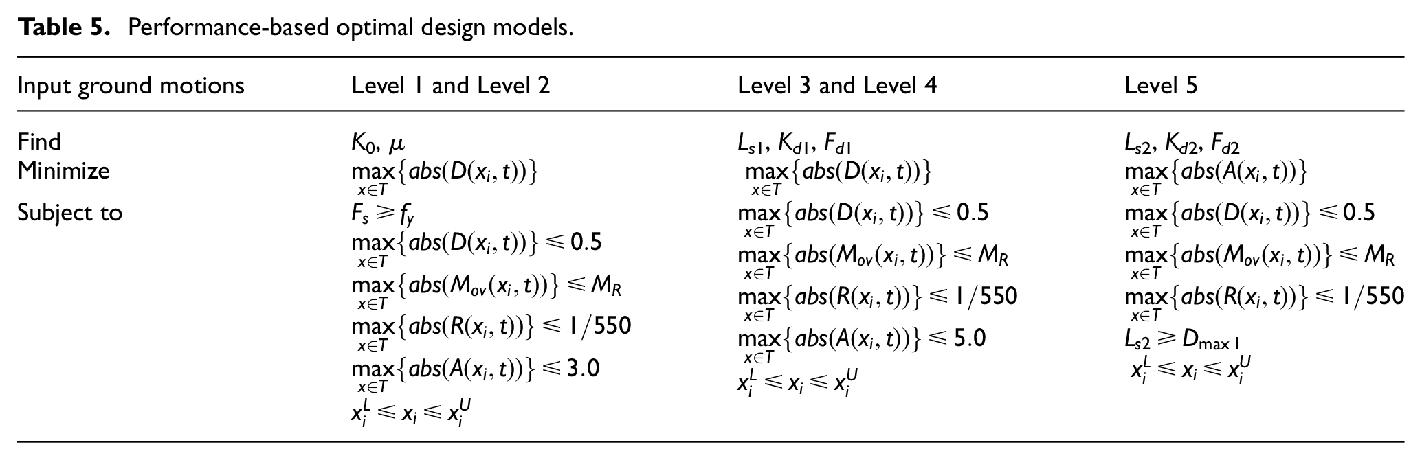
First, the design parameters of the isolation layer are optimized for wind loads (Level 1) and frequent earthquakes (Level 2). The optimization can be stated as follows: find the design vectors x1 (elastic stiffness K0) and x2 (friction coefficient μ) of the isolation layer, which satisfy the six inequality constraints, to minimize the seismic response displacement of the isolation layer. The six inequality constraints are shown in Table 5, which include the maximum displacement of the isolated structure, the maximum overturning moment of the structure, the maximum elastic interlayer displacement angle of the reinforced concrete frame structure, and the maximum seismic response acceleration of the isolated structure. In addition, D(xi,t), Mov(xi,t), R(xi,t), and A(xi,t) represent the displacement of the isolation layer, the overturning moment, the story drift angle, and the acceleration at time t when the design parameters are xi, respectively:
The isolation layer will not yield under various micro-vibrations and wind loads. This design requires that the design wind load fy is lower than the critical friction force of the sliding friction bearing Fs.
The maximum displacement of the isolation bearing
The overturning moment of the isolation structure
The limit value of the elastic story drift angle of the reinforced concrete frame structure
The maximum seismic response acceleration of the isolated structures
The upper
Second, the design parameters of the isolation layer are optimized for moderate (Level 3) and large earthquakes (Level 4). The optimization can be summarized as follows: find the design vectors x1 (preset clearance Ls1), x2 (elastic stiffness Kd1), and x3 (yield force Fd1), which satisfy the five inequality constraints that are listed in Table 5. It includes the maximum displacement of the isolated structure, the maximum overturning moment of the structure, the maximum elastic interlayer displacement angle of the reinforced concrete frame structure, and the maximum seismic response acceleration of the isolated structure. Optimize the minimization of the seismic response displacement of the isolation layer:
The maximum displacement of the isolation bearing
The overturning moment of the isolation structure
The limit value of the elastic story drift angle of the reinforced concrete frame structure
The maximum seismic response acceleration of the isolated structures
The upper
Finally, the design parameters of the isolation layer are optimized for extremely large earthquakes (Level 5). Find the design vectors x1 (preset clearance Ls2), x2 (elastic stiffness Kd2), and x3 (yield force Fd2), which satisfy the five inequality constraints that are similar to those for moderate and large earthquakes. Optimize the minimization of seismic response acceleration of the isolation layer:
The maximum displacement of the isolation bearing
The overturning moment of the isolation structure
The limit value of the elastic story drift angle of the reinforced concrete frame structure
The preset clearance Ls2 exceeds the maximum response displacement of the isolation layer Dmax1 under Level 3 and Level 4 earthquakes. This guarantees that the FDC2 will not be coupled when Level 3 and Level 4 earthquakes occur.
The upper
To overcome the design problems presented in Table 5, the SQP method, which is one of the most effective optimal design methods for nonlinear optimum design problems, was employed.
Analysis results
Optimized design variables
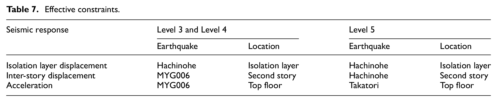
Table 6 shows the design variables obtained from the optimal design method. Table 7 shows the effective constraints of the ground motions and the locations of the maximum seismic responses applied during optimization. It can be seen that the seismic response of the isolated structure is very large, playing an effective role as a constraint in performance parameter optimization under Hachinohe, MYG006, and Takatori earthquakes. This result is consistent with the results shown in Figure 5. Specifically, the acceleration response spectrum of the isolated structure is the largest under the action of the above three ground motions near the natural vibration period of the isolated structure.
Optimal design results.

FDC: friction damper with coupling mechanism.
Effective constraints.
Maximum responses
Figure 7 shows the maximum responses of the isolated structures with and without two FDCs. In order to compare the maximum seismic responses of the structure under different working conditions, “With FDC1 + FDC2” was used to express the maximum responses of a structure with two FDCs, “With FDC1” was used to express the maximum responses of a structure with only one FDC, and “Without FDC” was used to express the maximum seismic response of a structure with fixed foundations. Based on Figure 7, the following conclusions can be derived:
In the “Without FDC” case, the maximum displacement of the isolation layer exceeded the designed safe distance after the Level 4 earthquakes, which means that the isolation structure would collide with the surrounding maintenance structure. Under Level 3 earthquakes, the displacement of the isolation layer was effectively controlled in the “With FDC1” and “With FDC1 + FDC2” cases. However, under the rare Level 5 earthquakes, if the FDC1 works alone, it cannot control the maximum displacement of the isolation layer within the safe range. Structural safety is ensured only when FDC1 and FDC2 work together.
In the “Without FDC” case, the maximum acceleration of the isolated structure was much greater than that in the “With FDC1” and “With FDC1 + FDC2” cases under Level 3 earthquakes. In the “Without FDC” case, the maximum acceleration of the isolation layer was amplified by two and three times under Level 4 and Level 5 earthquakes, respectively, due to the collision between the isolation structure and the surrounding maintenance structure. The maximum acceleration of the isolated structure in the “With FDC1 + FDC2” case was greater than that in the “With FDC1” case. However, only in half of the “Without FDC” cases, the isolation structure collided with the surrounding maintenance structure.
The maximum inter-story drift of the superstructure in the “Without FDC” case was very large. In all FDC cases, the maximum inter-story drift of the superstructure was effectively controlled within the requirements of the code (JGJ 3-2002, 2002).

Maximum response.
Figures 8 and 9 show the maximum drift and the maximum acceleration responses of each floor under El Centro earthquakes, respectively. As it can be seen, as the floor level increased, the maximum seismic responses of the superstructure increased. The isolated building with optimal parameters significantly minimizes the maximum story drift and the maximum acceleration of the superstructure.

Maximum story drift under El Centro earthquakes.

Maximum acceleration under El Centro earthquakes.
Time histories and hysteresis loops
For further comparison, the time histories of the isolation layer displacement and the top story acceleration for the MYG006 (Level 4) and Kashiwazaki (Level 5) earthquakes are presented in Figure 10(a) and (b), respectively. As it can be seen in Figure 10(a), the displacement of the isolation layer was controlled within the safe distance. The maximum acceleration of the structure decreased greatly. The acceleration did not increase, since the stiffness of the isolation layer increased at the moment of FDC1 coupling. Furthermore, the residual deformation was very small.
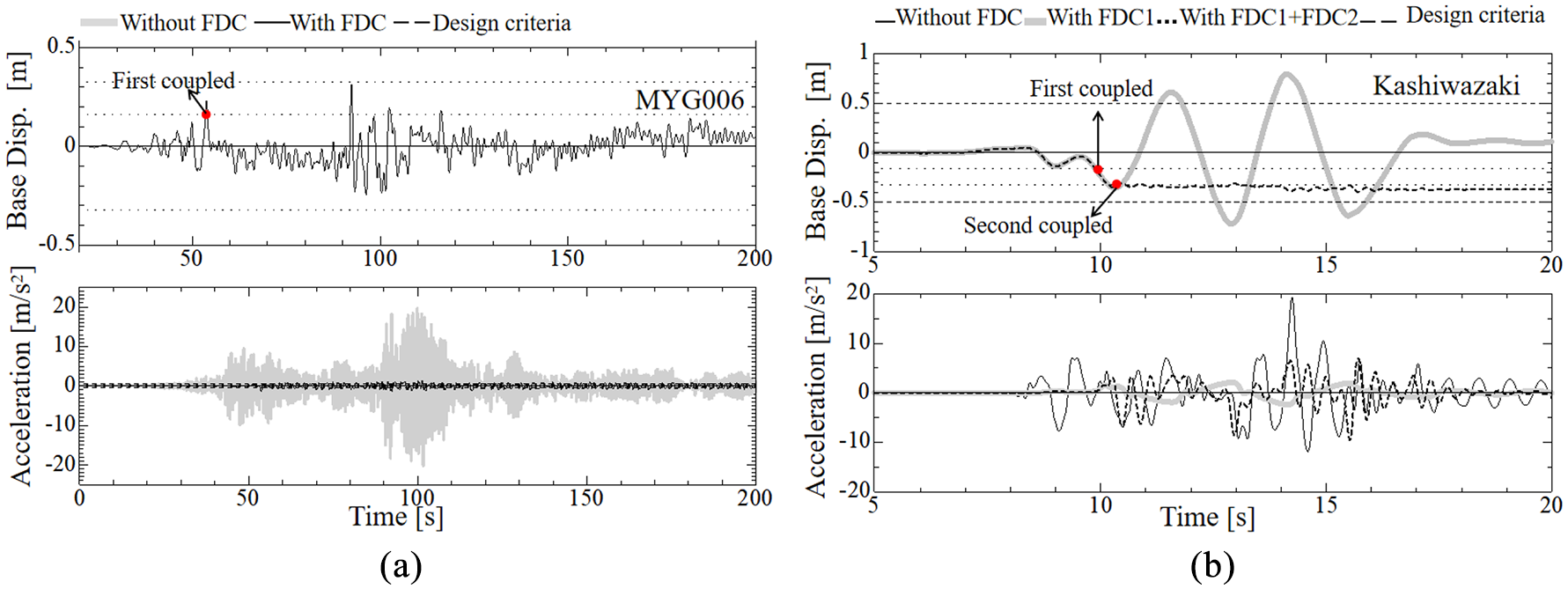
Response time histories of the “Without FDC” and “With FDC” under (a) MYG006 and (b) Kashiwazaki earthquakes.
As shown in Figure 10(b), the displacement of the isolation layer “With FDC1” still exceeded the reserved safe distance. When FDC1 and FDC2 cooperated, the displacement of the isolation layer was controlled within a safe range. Even though the acceleration of the structure exceeded that of the “With FDC1,” it was still very small compared to that of “Without FDC.” It can be deduced that FDC2 acts as a limiter.
Figure 11 shows the hysteresis loops of the FDCs. The hysteresis loops indicate that the two-coupling FDC could be effectively activated based on the level of input ground motion.
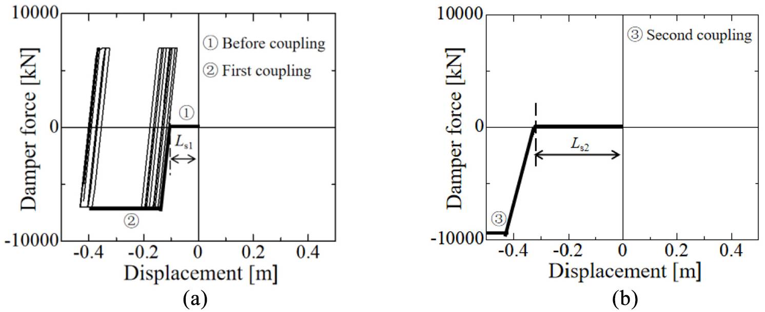
Hysteresis loops of (a) FDC1 and (b) FDC2.
Average maximum seismic response
Table 8 lists the average seismic maximum responses of the isolated structures with and without two FDCs. It can be seen that after the FDC was installed in the isolation layer, the maximum displacement control effect of the isolation layer was apparent and stable, which was beneficial to the structure, with the control amplitude ranging between 32% and 42%. The inter-story displacement remained the same, but was reduced under frequent earthquakes. The amplification of the maximum acceleration response of the isolated structure was inevitable. However, since it is a performance-based seismic isolation design, each seismic response—including the displacement of the seismic isolation layer, the acceleration, and other control indicators—can be optimized and improved through design.
Average maximum seismic response values.
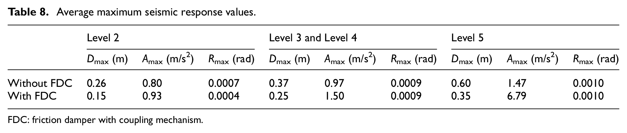
FDC: friction damper with coupling mechanism.
Conclusion
In this study, two-coupling FDCs were considered for a base-isolated structure. Performance-based design structural performance requirements, multiple design criteria, and multiple input ground motions were considered for the determination of the FDC variables. Moreover, the effectiveness of the performance-based optimization design method was discussed. According to the performance target and the performance level proposed in this article, the optimal design of a multi-phase friction damper was carried out. Based on the analytical results, the following conclusions were derived:
After the two-coupling FDC installation, the control effect of maximum seismic response was apparent. The average maximum displacement of the isolation layer was reduced by 31%–42%. The inter-story displacement of the superstructure was effectively controlled. The acceleration response was amplified. However, due to the performance-based optimization design, designers can fine-tune the seismic response displacement and acceleration by adjusting the performance objectives and levels.
Based on performance isolation design under different seismic action levels, the FDC multi-phase working mechanism, proposed in this article, can meet the different performance requirements of the isolation device. In this design, the FDC control effect was very good under frequent and moderate earthquakes. Moreover, FDC2 acts as a limiter under large and extremely large earthquakes.
The performance-based optimization design method, which is a development trend of the structural seismic design method, has the advantage of introducing specific quantitative performance objectives and levels to the three-level fortification requirements. According to the fortification intensity and the specific characteristics of the structure, the designer can select the performance target and the performance level for comprehensive evaluation and conduct proper isolation design.
Footnotes
Declaration of Conflicting Interests
The author(s) declared no potential conflicts of interest with respect to the research, authorship, and/or publication of this article.
Funding
The author(s) received no financial support for the research, authorship, and/or publication of this article.
