
Abstract
When carbon fiber reinforced polymer is applied to reinforce a steel plate, the end of it tends to debond which could cause a failure. In this article, the finite element model of carbon fiber reinforced polymer–reinforced steel plate was established based on the cohesive zone model and validated by the linear elasticity model and experiments at bonding stage and stripping stage, through which the stripping mechanism of the adhesive layer was studied. It had been proved by the test results of carbon fiber reinforced polymer–reinforced steel plate that the shear stress was the main factor of stripping damage, the whole stripping process consisted of elastic deformation, softening and stripping, and that the stripping began from the end to the middle of carbon fiber reinforced polymer until complete failure. Therefore, the cohesive zone model was suitable for the analysis of carbon fiber reinforced polymer–reinforced steel plate.
Introduction
Carbon fiber reinforced polymer (CFRP) has attracted increasing research interest due to their high strength-to-weight ratio and resistance to harsh environmental effects (Zhao and Zhang, 2007). One of the key technologies for CFRP-reinforced steel structure is to ensure that the adhesive between the CFRP and the steel structure bonds well. The adhesive layer is subjected to shear stress and normal stress. At the end of CFRP, there are serious stress concentrations of shear stress and normal stress, which can easily lead CFRP to degum from the steel structure (Haider et al., 2012; Kuhllnann and Gunther, 2002). Therefore, it is necessary to study the bonding properties of the adhesive between CFRP and steel structure to prevent the failure of the adhesive. According to the different research methods, they are always divided into two categories: the method based on the strength of the material and the method based on the cohesive zone model (CZM) (Fawzia et al., 2006; Nagai et al., 2012).
The method based on the strength of the material is judging the adhesive failure by the strength of the adhesive material through the stress analysis. The failure criteria usually include the maximum strain criterion and the maximum stress criterion. Due to sudden change of geometry at the end of CFRP, there are significant stress singulars at the end of the adhesive layer. In order to solve the problem, there were two kinds of solution: the point stress criterion of characteristic distance and the mean stress criterion of characteristic distance (Bocciarelli et al., 2009; Miyashtia and Nagai, 2011; Narmashiri and Jumaat, 2011; Nguyen et al., 2011). John et al. (1991) improved the method and proposed that the characteristic distance was equal to a normalized length from the end of CFRP. When the shear stress at the characteristic distance reached a critical value, the adhesive was damaged. Zhao (1991) predicted the failure of the adhesive by the average stress criterion of the characteristic distance which was equal to the thickness of the adhesive layer. The adhesive layer failed when the average value of the maximum principal stress reached the critical value.
The CZM (Blackman et al., 2003; Campilho et al., 2009) is a phenomenological model whose constitutive relation is usually expressed by the relationships between the cohesive force and the relative displacement of the interface. The constitutive model usually predicts the interface softening according to the interfacial strength (i.e. the maximum cohesive force) and predicts the interface damage based on the strain energy release rate. When the area below the cohesive force curve reaches the critical strain energy release rate, the interface begins to damage (Andersson and Stigh, 2004; Hogberg and Stigh, 2006; Leffler et al., 2007; Wu et al., 2012). Yu et al. (2012) demonstrated that the bond strength of the adhesive was related to the interfacial fracture energy, CFRP stiffness, and the thickness of the adhesive layer, and compared the theoretical bonding strength with the experimental bonding strength. Dehghani et al. (2012) described the deformation of the adhesive as a bond–slip model and established a two-dimensional plane strain finite element model of CFRP bonded steel plate. Goncalves et al. (2003) used a plastic bond–slip model to establish a mixed type of CZM to simulate the stripping process of single shear test of CFRP bonded aluminum plate.
To further reveal the stripping mechanism of CFRP-reinforced steel plate, a finite element model of the plate was established in this article based on the CZM. This model is validated by the linear elasticity model and experimental data at the bonding and stripping stages of the adhesive layer. The stripping mechanism and process of the adhesive layer were then studied based on the finite element model. Besides, a tensile experiment of CFRP-reinforced steel plate was carried out to verify the finite element model and the stripping mechanism.
Experimental tests
Material properties
The steel material used in the tests was S30400. It was obtained from tensile tests with an average yield stress of 309.5 MPa, average ultimate tensile strength of 584.3 MPa, and average Young’s modulus of 208.4 GPa. The CFRP material used in the tests was CUDP-H150/T700-E7 which was prepreg CFRP. According to the manufacturer’s data sheet, CFRP has Young’s modulus of 120 GPa, an ultimate tensile strength of 2000 MPa, and a thickness of 0.15 mm for each ply. It was flexible and could be applied through wet layup to curved structural surfaces.
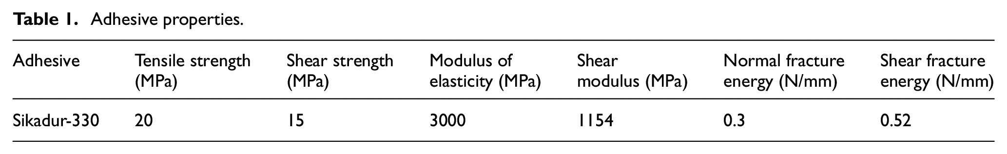
The epoxy resin used in bonding CFRP and steel was Sikadur-330. The thickness between CFRP and steel plates was 0.3 mm. According to the manufacturer’s data sheet, the properties of the adhesives are shown in Table 1.
Adhesive properties.
Specimen preparation
Specimens were designed to be dumbbell-shaped according to the standard “metal tensile test at ambient temperature” with both ends 55 mm wide and the middle 40 mm wide. The specimen dimensions are shown in Figure 1. The steel plate of each specimen has a length of 390 mm and a thickness of 3 mm. Both sides of the steel plate are pasted with 10 layers of CFRP. The width of CFRP is same as steel plate, the length of CFRP is 80 mm, and the entire thickness of each layer is 0.15 mm. To ensure that the CFRP is stripped at the left end to reduce the number of strain gauge points, the right end of CFRP is clamped by bolt. According to Saint-Venant’s principle, the bolt does not affect the force of the left end of CFRP.
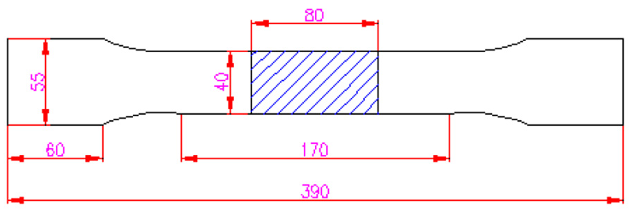
Specimen dimensions.
To monitor the stripping process of CFRP, strain gauges were attached to the steel plate and CFRP as shown in Figure 2. To monitor the position of CFRP starting to strip, a strain gauge was placed in the middle and at the two sides of the end CFRP, respectively; and to monitor the process of CFRP stripping, a row of strain gauges were placed in the middle of the longitudinal axis of CFRP. The strain gauges were products of BE120-3AA (AVIC Electric Instrument Co., Ltd.,) with a sensitive grid length of 3 mm and a nominal resistance of 120 Ω.
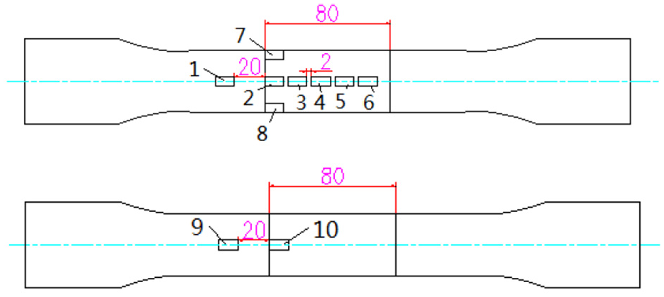
Arrangement of measuring points in specimen.
The process of CFRP paste steel plate was as follows: (1) first, sandblast the steel plate to remove oxide, contaminants, and so on, from the surface to form a certain surface roughness and enhance the bonding force between the adhesive and the steel plate; (2) scrub the surface of the steel plate with alcohol to further remove grease and contaminants; (3) mix Components A and B of Sikadur-330 in a certain proportion and stir for about 5 min; (4) apply the adhesive to the surface of the steel plate with a special brush to adhere the CFRP to the surface of the plate and make sure the thickness of the adhesive layer is 0.3 mm; and (5) finally, to make the specimen shape, place it under natural conditions for more than half a day and then in the incubator to be cured for 90 min at 45°C.
Experimental procedure
In this research, an MTS testing machine (see Figure 3) with a maximum capacity of 100 kN in tension with hydraulic grips was used to test the specimens under static tensile loads, with a loading rate of 2 mm/min.
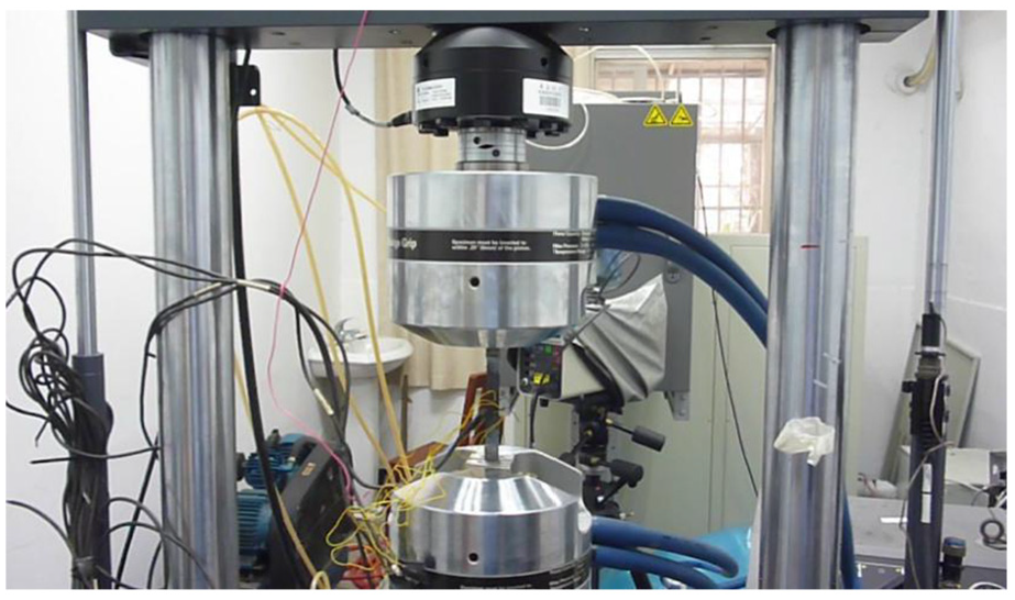
MTS testing machine.
In Figure 3, the testing machine clamps the steel plate of the specimen, and then slowly loads until the specimen is damaged. Test steps were as follows:
Step 1. Put the prepared specimen in the fixture of the testing machine and debug the DH5929 stress test system with the current state as the zero point of the strain.
Step 2. Open the testing machine, clamp the specimen, and check whether the strain of each measuring point has deviated from zero.
Step 3. Before the formal loading, apply an initial load of 5% of the maximum load to the specimen to ensure that it is in normal working condition.
Step 4. During the formal loading, the speed is controlled by displacement changes within 0.5–2 mm/min until the specimen is damaged.
Failure mode
The failure mode of CFRP-reinforced steel plate is shown in Figure 4. The end of CFRP slides 6 mm from the steel plate at the non-bolted clamping end (i.e. from the red line position in the box to the current position). The adhesive layer between the CFRP and the steel sheet is peeled off with most of the adhesive remaining on the CFRP, and only a small amount on the steel sheet. As the CFRP is not destroyed, the destruction of the sample was caused by the adhesive layer stripping off.

Failure mode of CFRP-reinforced steel specimen.
Finite element model
CZM
The CZM is a phenomenological model based on continuum damage mechanics and linear elastic fracture mechanics. Its constitutive equation defines relationships between the interface opening displacement and the cohesive force. It is generally believed that there is no coupling phenomenon between the normal cohesive force and the tangential cohesive force. That is, the normal displacement will not generate tangential cohesive force, and the tangential sliding will not lead to normal cohesive force (Ungsuwarungsru and Knauss, 1987). The constitutive equation is given as follows
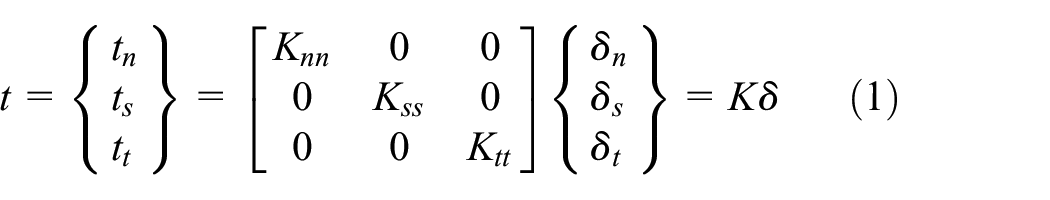
where t is the cohesive force vector; tn, ts, and tt are normal component and two tangential components of the cohesive force vector; δ is the interface opening displacement; δn, δs, and δt are normal component and two tangential components of the interface opening displacement; K is the interface stiffness; and Knn, Kss, and Ktt are normal component and two tangential components of the interface stiffness.
When the external load is small, the cohesive force is linear with the relative displacement. But with the increase in the load, the cohesive will be softened or cracked. At present, this softening phenomenon can be described by bilinear traction–separation law, trapezoidal traction–separation law, exponential traction–separation law, and polynomial traction–separation law, among which bilinear tension–displacement is most commonly used. The bilinear law of normal component is shown in Figure 5 (the other two tangential components are similar), in which the abscissa represents the opening displacement of the cohesive, the ordinate represents the cohesive force, tn.0 is the cohesive strength, δn.0 is the opening displacement corresponding to the cohesive strength, and δn.f is the opening displacement corresponding to the cohesive cracking. When the external load begins to act on the cohesive, the cohesive force is increased linearly with the load. When the cohesive force reaches the cohesive strength, it gradually reduces to zero. Reference variable n = max (δn) represents the maximum displacement in the loading history, and the bilinear law can be expressed as follows
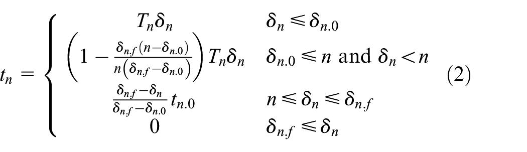
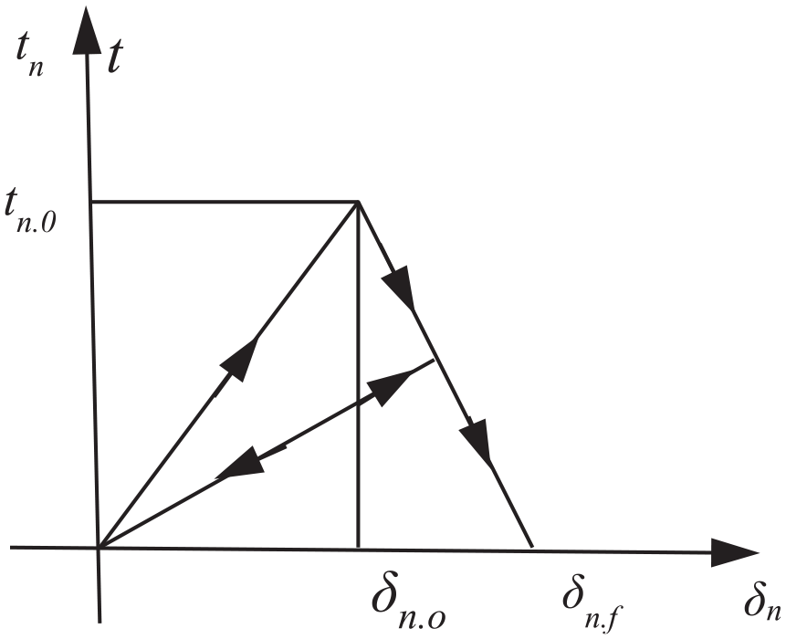
Bilinear law of CZM.
In general, normal stress tn may cause Type 1 crack mode, and tangential stresses ts and tt may lead to Types 2 and 3 crack modes. But the failure mode of the adhesive layer is a mixed one of Modes 1, 2, and 3 all or partially occurring simultaneously. The initial damage criterion for mixed damage is given by the quadratic nominal strain criterion, which can be expressed as
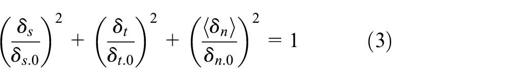
where δs.0, δt.0, and δn.0 are the opening displacements corresponding to the component cohesive strengths.
The damage criterion for mixed damage is the quadratic power criterion as follows
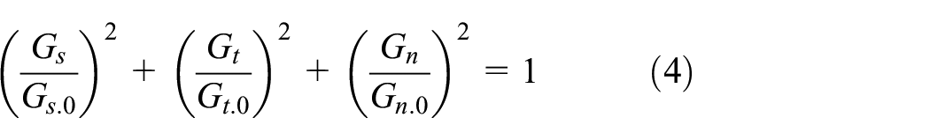
where Gs.0 and Gt.0 represent the interfacial fracture energy required to cause failure when subjected to pure Mode 2 loading. Gn.0 is the interfacial fracture energy required to cause failure when subjected to pure Mode 1 loading.
Finite element model
CFRP strengthened steel plate is a multilayer composite consisting of steel, adhesive layer, and CFRP. Teng et al. (2015) proposed that since the adhesive layer was thin, conventional finite elements could easily result in convergence, which can be addressed by the finite element model with the CZM. It is assumed in this article that the cohesive between steel plate and CFRP is bonded well, and the destruction of adhesive layer occurs only in the interior layer.
The finite element model of CFRP strengthened steel plate is shown in Figure 6, where Figure 6(b) is the partial detail of Figure 6(a). It is built by half of the model due to symmetric geometry and boundary conditions. For an accurate calculation of the stress of adhesive at the CFRP boundary, the size of boundary elements should be less than 1 mm, while the remaining elements were 3–5 mm. The steel plate is 3 mm thick and 40 mm wide. A total of 10 layers of CFRP are pasted on both sides of the steel plate with a CFRP length of 80 mm and a thickness of each layer 0.15 mm. The steel plate and the CFRP laminates are modeled using four-node reduced integration quadrilateral shell element (S4R), and the CFRP nodes correspond to the steel plate nodes. The adhesive layer is modeled using eight-node cohesive element (COH3D8), with nodes shared with CFRP and the steel plate, respectively. The Y-direction symmetric constraints are imposed on the nodes below, three translational degrees of freedom (DOFs) are constrained for the left end nodes, and a uniform load P is applied to the right end nodes. The model has a total of 24,770 elements and 14,877 nodes.
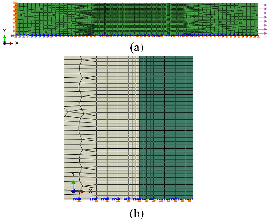
Finite element model of steel plate reinforced with CFRP: (a) global model, and (b) partial model.
Verification by linear elasticity model
The finite element model is validated by the linear elasticity model at the bonding stage. It is assumed here that steel plate, adhesive, and CFRP are all linear; the cross-sectional stress of the steel plate and CFRP is evenly distributed; the shear stress of the adhesive layer is also evenly distributed in thickness and width of the cross section; and the bending moment of CFRP is ignored for the symmetric structure and horizontal tensile loads. The calculation model of Figure 1 is shown in Figure 7. The axis origin is at the left end of CFRP, and the positive of x-axis is directed toward the right. The y-axis is perpendicular to the x-axis, and its positive is upward.
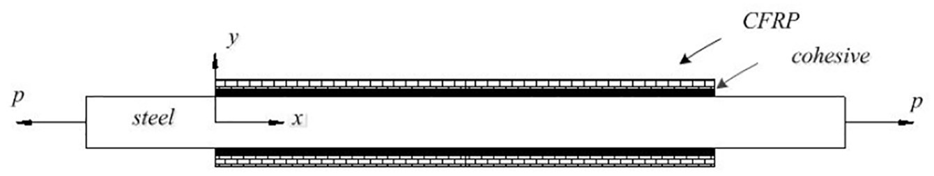
Calculation model of steel plate reinforced with CFRP.
Take a micro-segment at any position in the longitudinal direction of the CFRP in the reinforced test piece, the length of which is recorded as dx. See Figure 8 for the force bearing of the CFRP and the steel plate on the cross section where σa is the normal stress of the adhesive layer, τa is the shear stress, Nf and Qf are the axial force and shear force of the unit width CFRP, respectively, and Ns is the axial force of the unit width steel plate. Subscript a represents the adhesive layer, f the CFRP, and s the steel plate.
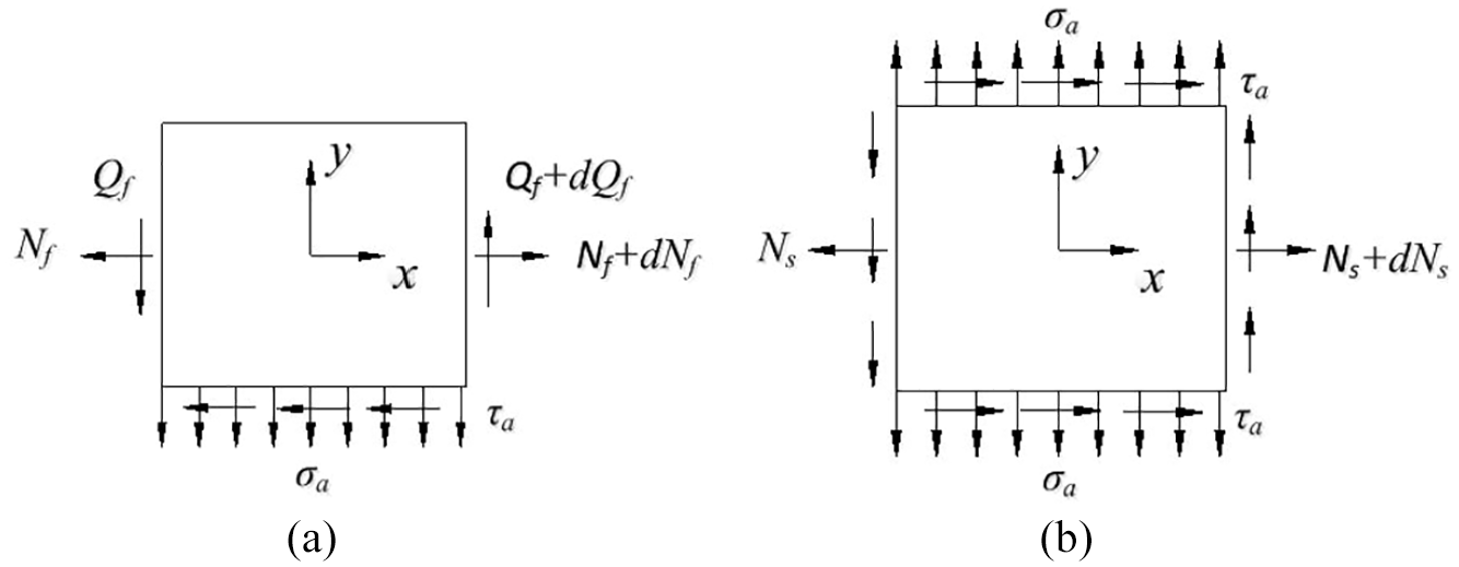
Stress on micro-segment of (a) CFRP and (b) steel plate.
According to the definition of shear strain, the expression of the adhesive shear strain γa is obtained as follows
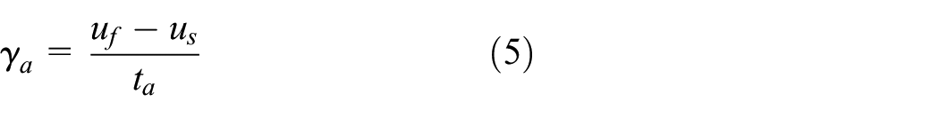
where uf is the axial displacement of CFRP, us is the axial displacement of the steel plate, and ta is the thickness of the adhesive layer.
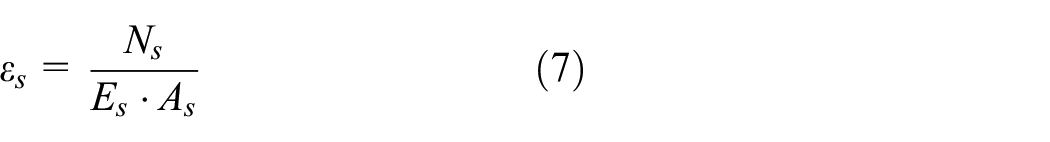
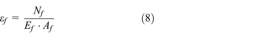
From equation (5), we have

where εs and εf are the longitudinal strains of steel plate and CFRP in horizontal direction, respectively
According to the balance of force conditions, the force of steel plate is

From equations (6)–(9), we have
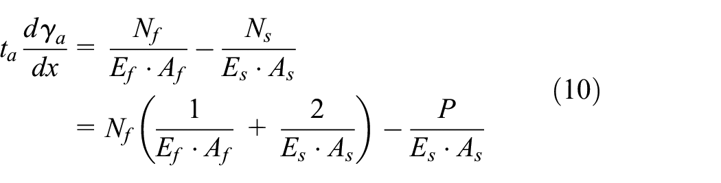
where Ef is the longitudinal elastic modulus of CFRP, Af is the cross-sectional area of CFRP, Es is the longitudinal elastic modulus of the steel plate, and As is the cross-sectional area of the steel plate.
The shear stress of the adhesive layer is obtained by the equilibrium equation of the micro-segment of CFRP in Figure 8

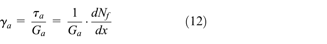
where Ga is the adhesive shear modulus.
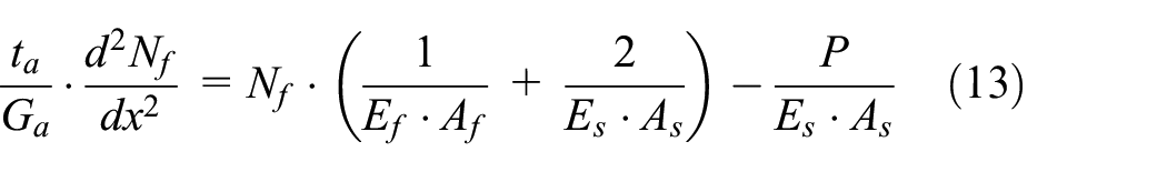
Substituting equation (12) into equation (10), the differential equation of CFRP tension Nf is obtained
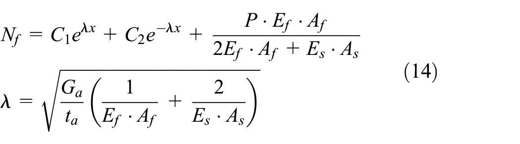
Solving the quadratic differential equation (13), we get
The forces at both ends of CFRP are 0. According to boundary conditions, the coefficients in equation (14) can be obtained. Substituting equation (14) into equation (11), the expressions of adhesive shear stress are as follows

Similarly, the expression of adhesive normal stress is as follows

The expression of CFRP longitudinal stress is obtained as follows

The finite element model is verified with the theoretical formula for the shear stress and the normal stress of adhesive layer. The shear stresses calculated by the finite element model and the theoretical formula are shown in Figure 9, displaying good agreement of the shear–stress curve of simulation with theoretical calculation. The relative disparity between the maximum simulated shear stress and the maximum theoretical shear stress is 8.1%, with the former standing at 9.17 MPa and the latter 9.98 MPa. The minimum simulated shear stress is 0.0028 MPa, and the minimum theoretical shear stress is 0.0048 MPa, both very close to 0. So, the finite element model can accurately calculate the shear stress of adhesive layer at the linear elastic stage.
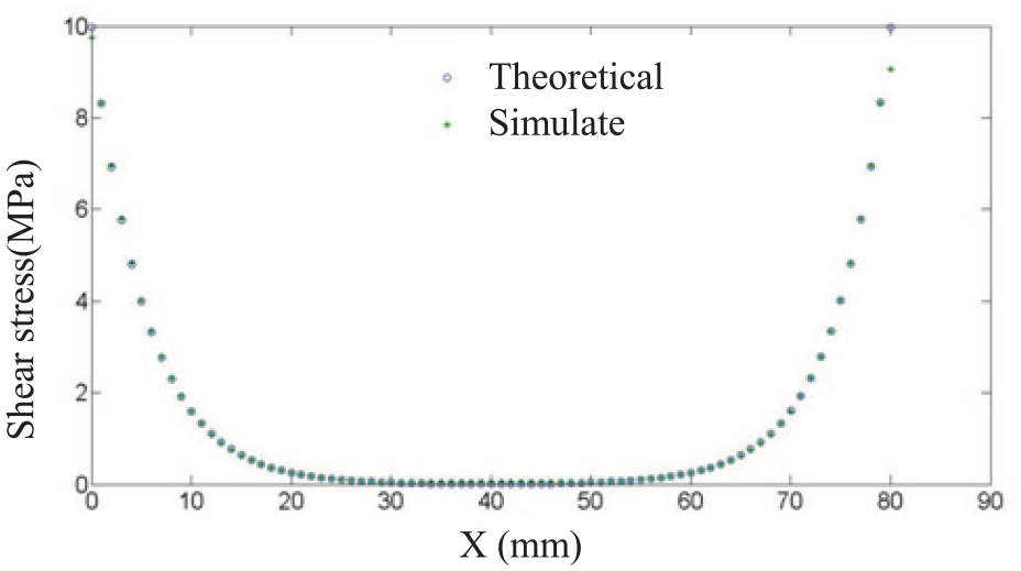
Shear stresses calculated by the finite element model and the theoretical formula.
The normal stresses calculated by the finite element model and the theoretical formula can be seen in Figure 10, which shows that the normal stress curve of simulation tallies with the theoretical calculation. The maximum simulated normal stress is 0.0014 MPa, and the maximum theoretical normal stress is 0.0018 MPa, both very close to 0. The minimum simulated normal stress is −1.72 MPa and the minimum theoretical normal stress is −1.37 MPa, with a large relative error of 25.5% that may result from the theoretical formula ignoring the bending moment of CFRP. Therefore, the finite element model can accurately calculate the normal stress of adhesive layer at the linear elastic stage.

Normal stresses calculated by the finite element model and the theoretical formula.
Verification by test data
The finite element model is validated at the bonding and stripping stages of the adhesive layer by test data as follows. Figure 11 shows the test strains and simulation strains at the measuring points on CFRP at the bonding stage, the unit of the strain being με. The test strains are based on the Wheatstone bridge theory, which are converted to logarithmic strains, so the simulation strains and test strains are all logarithmic strains. The external load is 33,640 N. The experimental strains and the simulation strains at the measured points on the CFRP all increase with the distance between the measuring points and the end of the CFRP. The average relative error between simulated and experimental strains is 2.3% for all points except Point 2 where the relative error is a little larger as the distance between Point 2 and the end of the CFRP is too small and the strain gradient of CFRP is too large for the strain gauge to test accurately. In general, the finite element model can accurately simulate the stress distribution of CFRP at the bonding stage.

Test trains and simulation strains at measuring points on CFRP.
The local finite element model of the CFRP end at the stripping stage of the adhesive layer is shown in Figure 12. The adhesive layer at the end of the CFRP is removed, indicating that the adhesive element has been stripped. In the tensile test, the end of CFRP with non-bolted clamping is stripped first. Therefore, the stripping location of the adhesive layer simulated by the finite element model is consistent with the result of the experiment. When the end of CFRP begins to strip, the simulated strain on the steel plate is 35,476, the experimental strain on the steel plate is 35,750, and their relative error is 0.77%, showing that the finite element model can accurately predict the location and external load of the adhesive layer stripping.
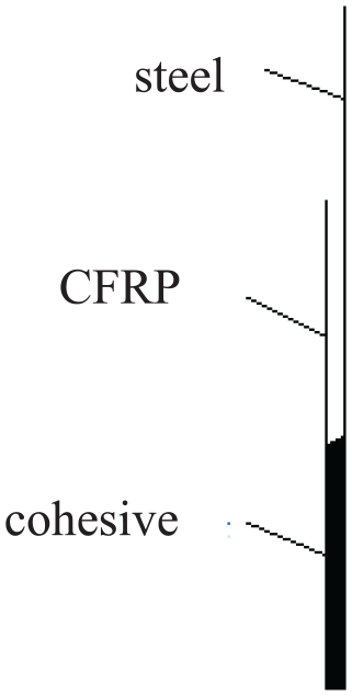
Local finite element model of CFRP end when the adhesive strips.
Analysis of adhesive layer stripping mechanism
In CFRP-reinforced steel plate, adhesive layer and CFRP bear the load as a whole. Partial load of the steel plate is transferred to CFRP through adhesive layer which is often the weak link that easily fails. When the load transferred by the adhesive layer reaches a certain value, the latter will be damaged and stripped, making it unable to deliver load to the CFRP and likely to cause the adjacent adhesive to peel off, which puts the CFRP-reinforced steel plate in an unfavorable condition. The stripping mechanism and stripping process of the adhesive layer are analyzed based on the finite element model, including stiffness damage of adhesive layer, the adhesive layer stress, and the CFRP stress.
Stiffness damage of adhesive layer
According to the finite element calculation results of the CFRP-reinforced steel plate, the damage process of the adhesive layer can boil down to three stages as shown in Figure 13, where P represents the load when the adhesive layer begins to be stripped. The first stage is the elastic deformation stage (0–0.5 P), where the damage coefficients of all adhesive layer nodes are 0, the stresses on all the adhesive nodes are less than their strengths, and the adhesive layer does not soften. The second stage is the softening stage (0.5–1 P), where the stiffness of the adhesive layer at the end of CFRP begins to soften. The stiffness damage coefficient increases and the damage gradually moves to the middle nodes. The third stage is the stripping stage (greater than P), where the stiffness damage coefficient of the adhesive layer at the end of CFRP reaches 1, the end of the adhesive layer has been stripped, and as the load increases, the stripping position gradually moves to the middle of the adhesive layer until the whole layer is stripped. It can be seen that the damage process of the adhesive layer starts with the softening of its end which is then stripped off, and the stripping position gradually moves away from the end to the middle of the adhesive layer.
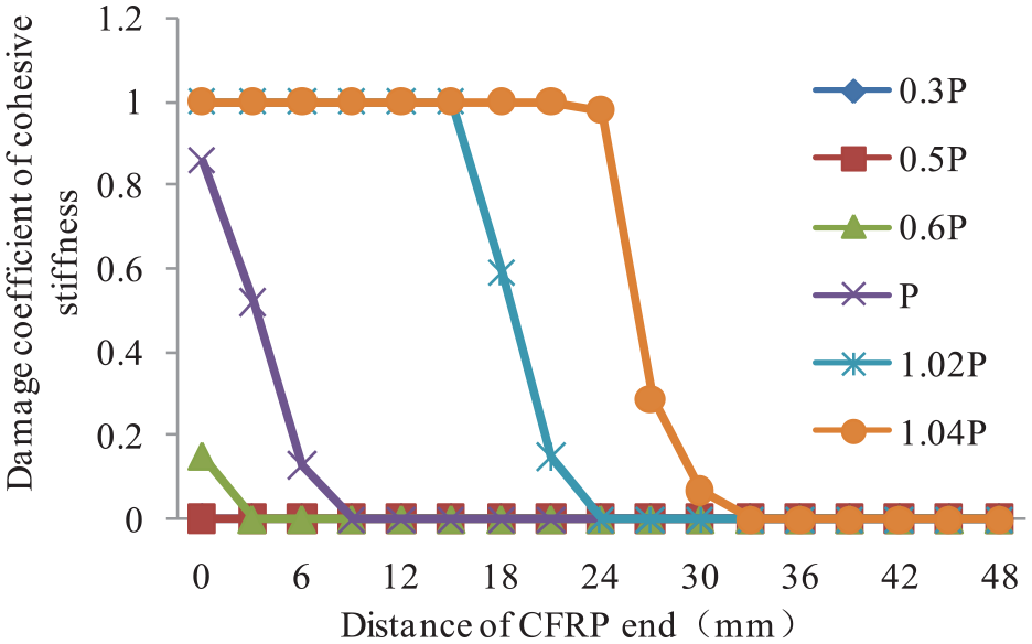
Damage coefficient of adhesive layer stiffness as load increases.
The relationship between the stiffness damage coefficient of the adhesive layer and the strain on the steel plate at the end of CFRP is shown in Figure 14, where the abscissa indicates the strain on the steel plate and the ordinate of the stiffness damage coefficient, a is the initial load of softening of the end of the adhesive layer, b is the yield load of the steel plate, and c is the initial load when the end of the layer begins to be stripped. When the end of the adhesive layer begins to soften, the steel plate is still at the elastic stage, and when the former begins to be stripped, the latter is at the yield stage. As the steel plate has been yielded, more external load is born for CFRP which accelerates the damage rate of the adhesive layer.
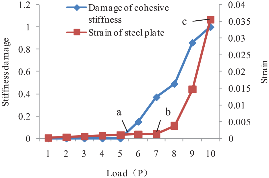
Relationship between the stiffness damage coefficient of the adhesive layer and the strain on steel plate at the end of CFRP.
Adhesive layer stress
In the CFRP-reinforced steel plate, the adhesive layer transfers the load from the plate to the CFRP. In essence of this, the stripping of adhesive layer is caused by stress of two types: shear stress and normal stress.
The adhesive stress of the CFRP-reinforced steel plate at load P is shown in Figure 15, where the maximum shear stress (14.6 MPa) close to the allowable shear strength of 15 MPa (data from the vendor) and normal stress (2.2 MPa) smaller than the allowable tensile strength of 20 MPa (data from the vendor) of the adhesive layer are both located at the ends of the CFRP, which shows that the damage of the adhesive layer usually occurs at the end of the CFRP, and the shear stress plays a major role in this regard.
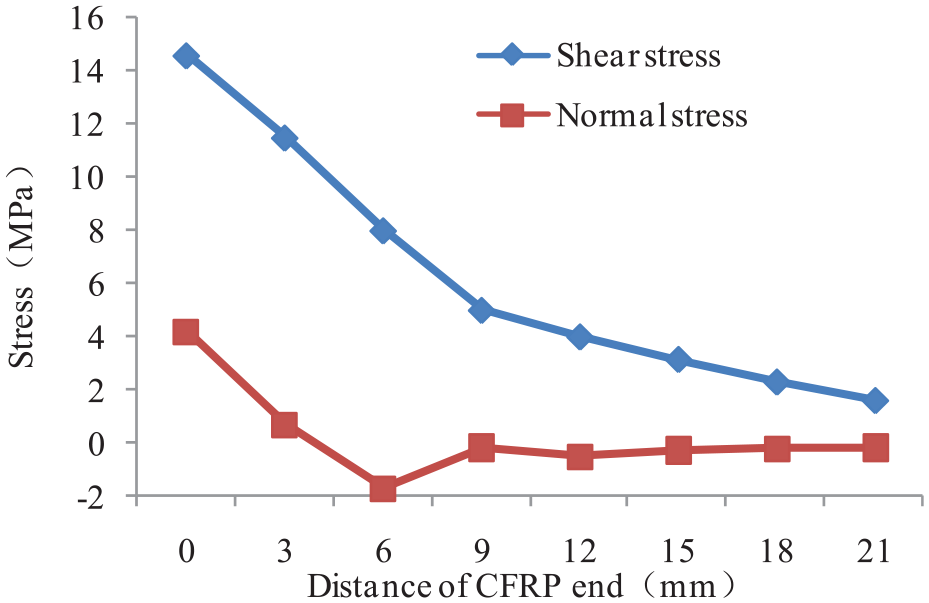
Adhesive stress on CFRP-reinforced steel plate.
The shear stress of cohesive as load increases is shown in Figure 16. At the elastic deformation stage (0–0.5 P) and the softening stage (0.5–0.6 P), the maximum shear stress on the adhesive layer is located at the end of the layer, and the shear stress increases with the load. At the softening stage (0.6–1 P), the shear stress on the end of the adhesive layer is 14 MPa, which is close to the shear strength of the adhesive layer. And as the shear stress on the end of the adhesive layer rises with the load, the stiffness starts to soften and the maximum shear stress continues moving to the middle. At the stripping stage (greater than P), the shear stress on the end of the adhesive layer is close to 0 MPa, and the node with the largest shear stress continues to move away from the end to the middle.
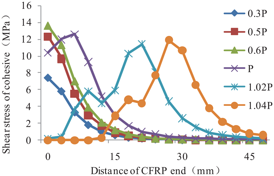
Shear stress of cohesive with load increasing.
The normal stress of cohesive as load increases is shown in Figure 17. At the elastic deformation stage (0–0.5 P) and the softening stage (0.5–1 P), the maximum normal stress on the adhesive layer is located at the end of the adhesive layer. The amplitude is about 2 MPa, which is much smaller than the maximum tensile strength of the adhesive layer of 20 MPa, so the normal stress has little effect on the stripping of the adhesive layer. The normal stress on the end of the adhesive layer is tensile stress which gradually turns to compressive stress near the end and is ultimately reduced to 0 MPa in the middle. At the stripping stage (greater than P), the normal stress on the end of the adhesive layer is close to 0 MPa, and the node with the largest normal stress continues to move away from the end to the middle.
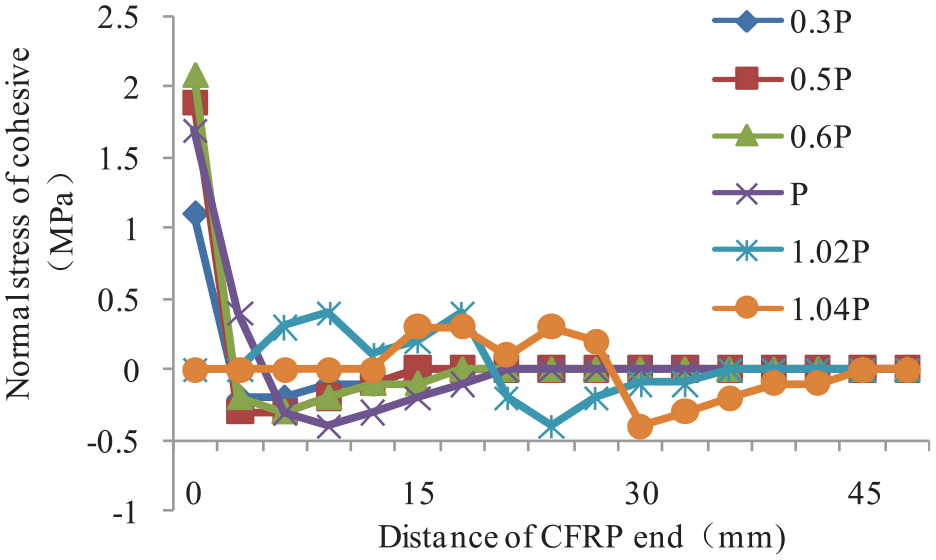
Normal stress of cohesive with load increasing.
CFRP stress
Figure 18 shows how the longitudinal stress on CFRP changes as load increases. At the elastic deformation stage (0–0.5 P) and the softening stage (0.5–0.6 P), the stress on the end of CFRP increases with the load, which corresponds to the increase in the shear stress on the end of the adhesive layer. At the softening stage (0.6–1 P), with the load increasing, the stress on the end of the CFRP drops, corresponding to the decrease in the shear stress on the end of the adhesive layer. And at the stripping stage (greater than P), the stress on the CFRP end is zero. From the above analysis, we can see that the longitudinal stress change on CFRP corresponds well to the shear stress change on the adhesive layer. When the shear stress on the end of the adhesive layer increases, the stress on the end of the CFRP also goes up.
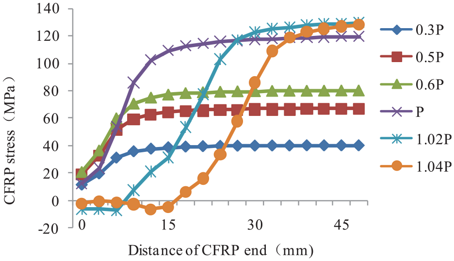
Longitudinal stress on CFRP with load increasing.
Figure 19 shows the steel plate and CFRP strains at the same positions before the adhesive layer is softened. As the distance from the end of the CFRP increases, the strains on the CFRP go up, the strains on the steel plate decrease, and their strain differences reduce. Away from the end of the CFRP, the CFRP strains are identical to the steel strains.
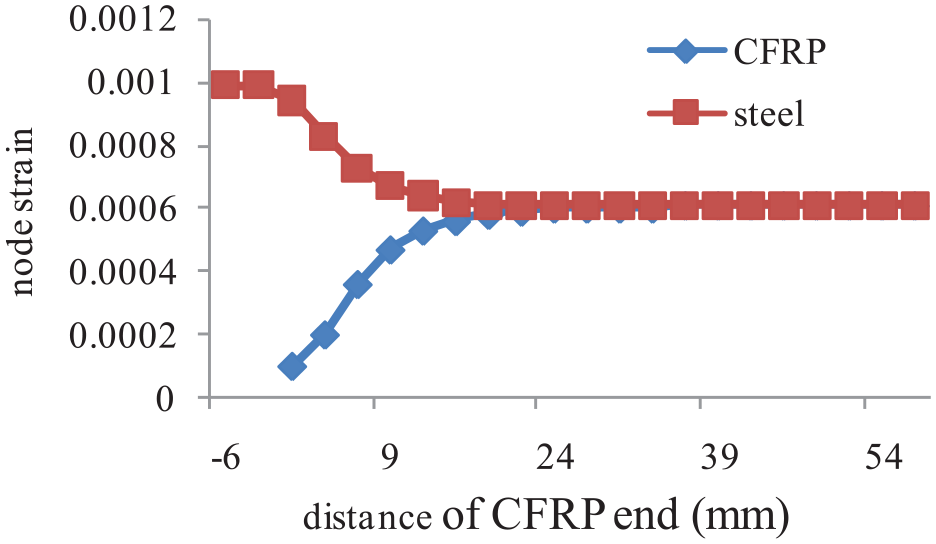
Strains on steel plate and CFRP before the adhesive stripping.
The CFRP strain and steel plate stress curves are shown in Figure 20, where Figure 20(b) is the partial detail of Figure 20(a). The stresses on the steel plate are determined by the strain at Point 1 on the steel plate and the stress–strain curve of the steel S30400, the test strains of CFRP are measured by strain gauges, and the FEA strains of CFRP are calculated by finite element model. From this figure, the test strains and the FEA strains on the CFRP are in agreement. The tensile process of the sample is divided into three stages. The first stage is the bonding stage where CFRP strain increases with the stress on the steel plate. When the steel plate exceeds a yield stress of 309.5 MPa, the strain rate of CFRP increases more than before. The maximum stress on the steel plate is 360 MPa, which exceeds its yield stress at this stage. The second stage is the stripping stage where the strain at Point 3 closest to the end of the CFRP drastically declines first, and then the strain at Point 5 drops sharply until the strains at all points on the CFRP reduce to steady values. It can be observed from the test that the end of the CFRP has begun to strip. The third stage is the CFRP failure phase where the strains on the CFRP remain constant and all loads are supported by the steel plate. The test strain value at this stage is not 0, which may be caused by zero drift during the strain test.
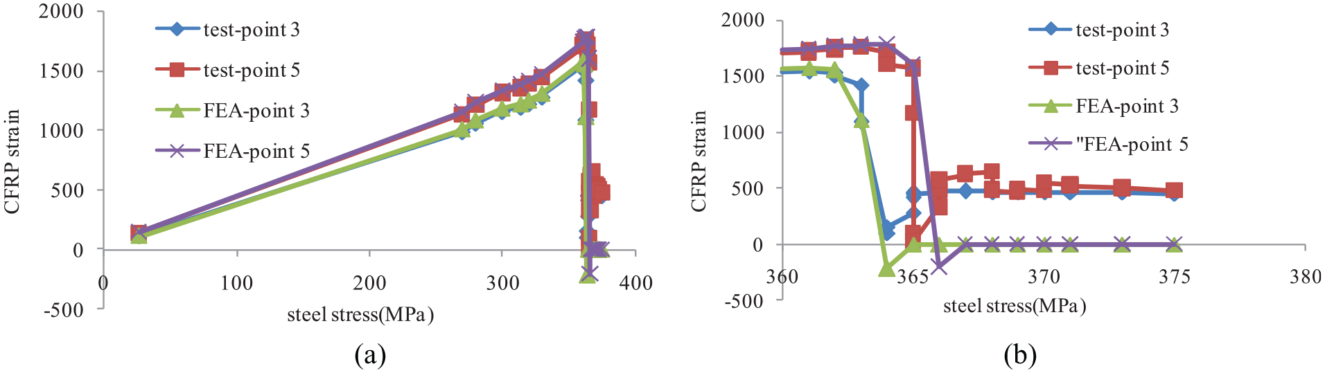
CFRP strain and steel plate stress curves: (a) overall curve, and (b) partial model.
Conclusion
Based on the CZM, the finite element model of CFRP-reinforced steel plate is established in this article that helps the study on the stripping mechanism and stripping process of the adhesive layer which have been verified by the tensile experiment of CFRP-reinforced steel plate. The conclusions are as follows:
The finite element model of CFRP-reinforced steel plate is established according to CZM, which is validated at the bonding stage and the stripping stage of the adhesive layer by linear elasticity model and test data. This model is able to accurately simulate the stress distribution at the bonding stage and predict the location and external load of the adhesive layer stripping.
The stripping process of the adhesive layer has three stages: the elastic deformation stage, the softening stage, and the stripping stage.
Based on the finite element model, the stripping mechanism of the adhesive layer is revealed, including stiffness damage law of adhesive layer, adhesive layer stress law, and CFRP stress law.
The adhesive layer is mainly subjected to shear stress and normal stress, with the former playing a major role in the damage of the adhesive layer.
Footnotes
Declaration of Conflicting Interests
The author(s) declared no potential conflicts of interest with respect to the research, authorship, and/or publication of this article.
Funding
The author(s) disclosed receipt of the following financial support for the research, authorship, and/or publication of this article: The project was supported by the Natural Science Foundation of China (Grant No. U1737112) and Chinese Postdoctoral Station of Yihua Life Science and Technology Co., Ltd (Grant No. 201141).